IPhO 2000 · Theory problem 2
Charge-to-mass ratio of the electron (magnetic focusing in a CRT; beta particles between charged plates)
(a) A cathode ray tube (CRT), consisting of an electron gun and a screen, is placed within a uniform constant magnetic field of magnitude \(\mathbf B\) such that the magnetic field is parallel to the beam axis of the gun, as shown in figure 2.3.
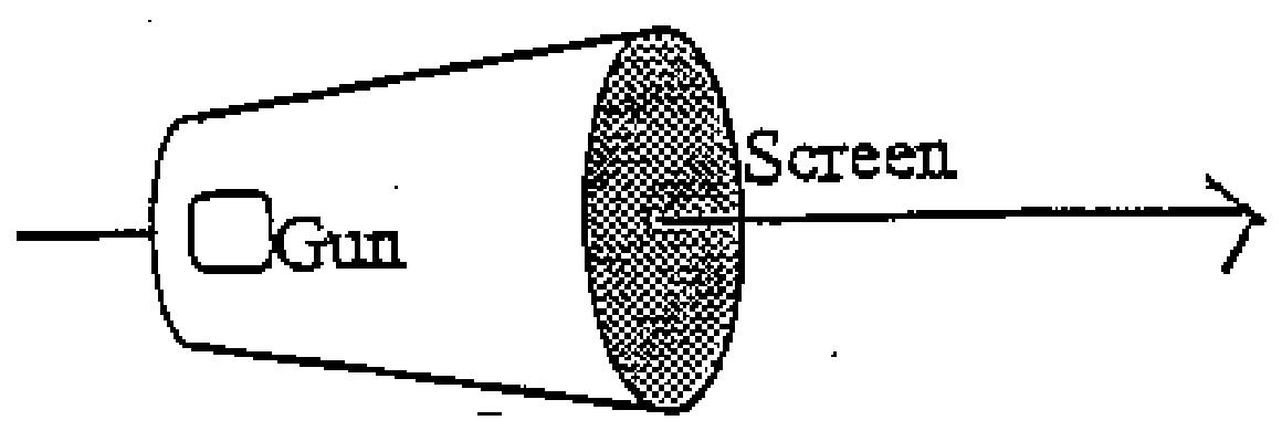
Figure 2.3
The electron beam emerges from the anode of the electron gun on the axis, but with a divergence of up to \(5^\circ\) from the axis, as illustrated in figure 2.4. In general a diffuse spot is produced on the screen, but for certain values of the magnetic field a sharply focused spot is obtained.
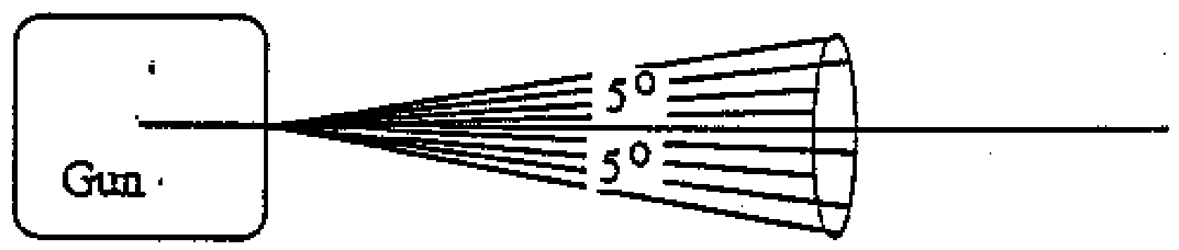
Figure 2.4
By considering the motion of an electron initially moving at an angle \(\beta\) (where \(0\leq\beta\leq5^\circ\)) to the axis as it leaves the electron gun, and considering the components of its motion parallel and perpendicular to the axis, derive an expression for the charge to mass ratio \(e/m\) for the electron in terms of the following quantities:
the smallest magnetic field for which a focused spot is obtained,
the accelerating potential difference across the electron gun \(V\)
(note that \(V<2\ \mathrm{kV}\)),
and \(D\), the distance between the anode and the screen.
Write your expression in the box provided in section 2a of the answer sheet.
(b) Consider another method of evaluating the charge to mass ratio of the electron. The arrangement is shown from a side view and in plan view (from above) in figure 2.5, with the direction of the magnetic field marked \(\mathbf B\). Within this uniform magnetic field \(\mathbf B\) are placed two brass circular plates of radius \(\rho\) which are separated by a very small distance \(t\). A potential difference \(V\) is maintained between them. The plates are mutually parallel and co-axial, however their axis is perpendicular to the magnetic field. A photographic film, covers the inside of the curved surface of a cylinder of radius \(\rho+s\), which is held co-axial with the plates. In other words, the film is at a radial distance \(s\) from the edges of the plates. The entire arrangement is placed in vacuo. Note that \(t\) is very much smaller than both \(s\) and \(\rho\).
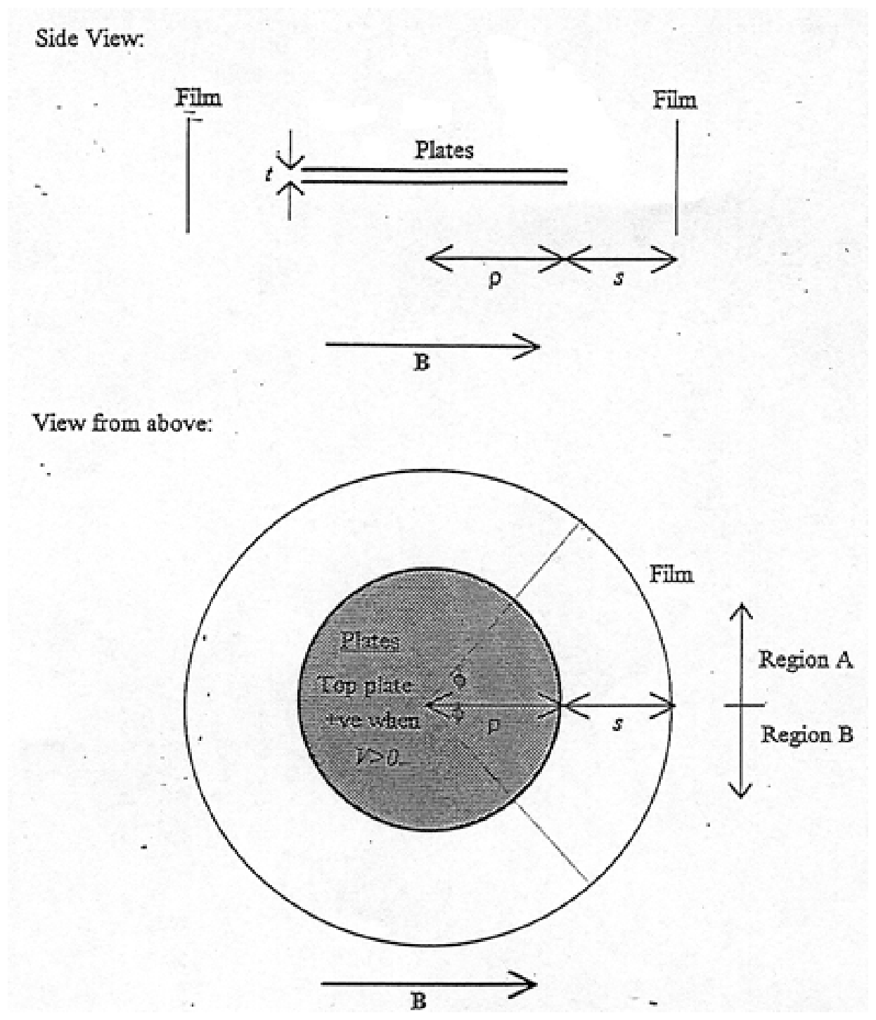
Figure 2.5
A point source of \(\beta\) particles, which emits the \(\beta\) particles uniformly in all directions with a range of velocities, is placed between the centres of the plates, and the same piece of film is exposed under three different conditions:
firstly with \(B=0\), and \(V=0\),
secondly with \(B=B_0\), and \(V=V_0\), and
thirdly with \(B=-B_0\), and \(V=-V_0\);
where \(V_0\) and \(B_0\) are positive constants. Please note that the upper plate is positively charged when \(V>0\) (negative when \(V<0\)), and that the magnetic field is in the direction defined by figure 2.5 when \(B>0\) (in the opposite direction when \(B<0\)). For this part you may assume the gap is negligibly small.
Two regions of the film are labelled A and B on figure 2.5. After exposure and development, a sketch of one of these regions is given in figure 2.6. From which region was this piece taken (on your answer sheet write A or B)? Justify your answer by showing the directions of the forces acting on the electron.
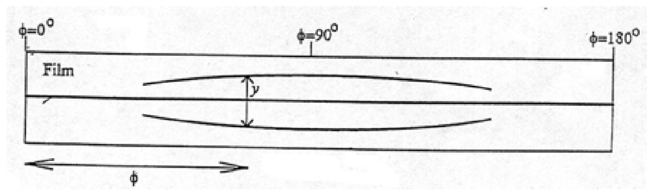
Figure 2.6
(c) After exposure and development, a sketch of the film is given in figure 2.6. Measurements are made of the separation of the two outermost traces with a microscope, and this distance (\(y\)) is also indicated for one particular angle on figure 2.6. The results are given in the table below, the angle \(\phi\) being defined in figure 2.5 as the angle between the magnetic field and a line joining the centre of the plates to the point on the film.
| Angle to field /degrees | \(\phi\) | 90 | 60 | 50 | 40 | 30 | 23 |
|---|---|---|---|---|---|---|---|
| Separation /mm | \(y\) | 17.4 | 12.7 | 9.7 | 6.4 | 3.3 | End of trace |
Numerical values of the system parameters are given below:
\[ B_0=6.91\ \mathrm{mT} \qquad V_0=580\ \mathrm V \qquad t=0.80\ \mathrm{mm} \] \[ s=41.0\ \mathrm{mm} \]
In addition, you may take the speed of light in vacuum to be \(3.00\times10^8\ \mathrm{m\,s^{-1}}\), and the rest mass of the electron to be \(9.11\times10^{-31}\ \mathrm{kg}\).
Determine the maximum \(\beta\) particle kinetic energy observed.
Write the maximum kinetic energy as a numerical result in eV in the box on the answer sheet, section 2f.
(d) Using the information given in part (f) [i.e. part (c) above], obtain a value for the charge to rest mass ratio of the electron. This should be done by plotting an appropriate graph on the paper provided.
Indicate algebraically the quantities being plotted on the horizontal and vertical axes both on the graph itself and on the answer sheet in the boxes provided in section 2g.
Write your value for the charge to mass ratio of the electron in the box provided on the answer sheet, section 2g.
Please note that the answer you obtain may not agree with the accepted value because of a systematic error in the observations.
Official English text of the problem.
Answers
-
(a) For the smallest positive focusing field \(B_{\min}\), \[ \boxed{\frac em\simeq\frac{8\pi^2V}{B_{\min}^{\,2}D^2}}. \]
-
(b) \(\boxed{\text{Region B}}\). For \(B=B_0,\ V=V_0\), the electric force is upward and the magnetic force downward. Reversing both fields reverses both forces.
-
(c) \[ \boxed{K_{\max}\simeq6.4\times10^5\ \mathrm{eV}} \] corresponding to \(v_{\max}\simeq2.69\times10^8\ \mathrm{m\,s^{-1}}\).
-
(d) Plot \(Y=y\) vertically against the dimensionless horizontal quantity \[ X=\sin\phi\sqrt{\sin^2\phi- \left(\frac{V_0}{B_0tc}\right)^2}. \] The straight line has slope approximately \(1.855\times10^{-2}\ \mathrm m\), giving \[ \boxed{\frac{e}{m_0}\simeq1.68\times10^{11}\ \mathrm{C\,kg^{-1}}}. \]
Solution
Throughout, \(e>0\) denotes the magnitude of the electron charge; the electron’s charge is \(-e\). Its rest mass is \(m_0\).
(a)
Since the accelerating voltage is below \(2\ \mathrm{kV}\), the electron’s kinetic energy is much smaller than its rest energy. We use nonrelativistic mechanics, with \(m\simeq m_0\):
\[ eV=\frac12mv^2. \]
The velocity components on leaving the gun are \[ v_\parallel=v\cos\beta,\qquad v_\perp=v\sin\beta. \]
The magnetic field exerts no force parallel to itself. The parallel motion is therefore uniform, while the perpendicular motion is circular, with \[ r=\frac{mv_\perp}{eB}, \qquad \omega=\frac{eB}{m}, \qquad T=\frac{2\pi m}{eB}. \]
The resulting trajectory is a helix. An electron starting on the axis returns to the axis after each complete revolution. The smallest positive focusing field corresponds to one revolution before reaching the screen, so \[ D=v\cos\beta\,T =\frac{2\pi mv\cos\beta}{eB_{\min}}. \]
Squaring and substituting \(v^2=2eV/m\) gives \[ \frac em =\frac{8\pi^2V\cos^2\beta}{B_{\min}^{\,2}D^2}. \]
For the narrow beam, \(\beta\leq5^\circ\), we take \(\cos\beta\simeq1\). Hence \[ \boxed{\frac em\simeq\frac{8\pi^2V}{B_{\min}^{\,2}D^2}}. \]
The focusing is approximate for a beam containing different \(\beta\): their axial velocities differ slightly. At \(5^\circ\), \(1-\cos\beta\) is only about \(0.0038\).
(b)
The Lorentz force is \[ \mathbf F=-e\left(\mathbf E+\mathbf v\times\mathbf B\right). \]
For \(V=V_0>0\), the upper plate is positive, so the electric field points downward and the electric force on an electron points upward.
For \(B=B_0>0\), applying the cross-product rule to the plan view gives:
| Electron travelling toward | Electric force | Magnetic force |
|---|---|---|
| Region A | Upward | Upward |
| Region B | Upward | Downward |
With a negligibly small gap, electrons can traverse the plates only when their vertical forces balance. This is possible in region B.
Let \(\theta\) be the angle between the electron’s velocity and the magnetic field while it travels between the plates. Neglecting fringing, \[ E_0=\frac{V_0}{t}. \] Force balance requires \[ eE_0=eB_0v\sin\theta, \] or \[ \boxed{v\sin\theta=\frac{V_0}{B_0t}}. \]
Reversing both \(B\) and \(V\) reverses both forces, so they still balance for electrons travelling toward region B.
After an electron leaves the plates, the electric force disappears while the magnetic force remains. Thus:
- \(B=B_0,\ V=V_0\) produces the lower curved trace.
- \(B=-B_0,\ V=-V_0\) produces the upper curved trace.
- \(B=V=0\) produces the central straight trace.
These are the three traces shown in figure 2.6, establishing \[ \boxed{\text{Region B}}. \]
(c)
We use the thin-gap approximation and, to leading order in the subsequent deflection, identify the electron’s departure angle \(\theta\) with the observed angle \(\phi\). Define \[ u=\frac{V_0}{B_0t}. \] Numerically, \[ u=\frac{580}{(6.91\times10^{-3})(0.80\times10^{-3})} =1.0492\times10^8\ \mathrm{m\,s^{-1}}. \]
The velocity-selection condition becomes \[ v(\phi)=\frac{u}{\sin\phi}. \]
As \(\phi\) decreases from \(90^\circ\), the selected speed increases. The smallest observed angle, \(23^\circ\), therefore corresponds to the maximum speed: \[ v_{\max} =\frac{1.0492\times10^8}{\sin23^\circ} =2.6852\times10^8\ \mathrm{m\,s^{-1}} =0.8951c. \]
The “End of trace” entry specifies this angular cutoff; it supplies no numerical measurement of \(y\).
Relativistic kinetic energy is required: \[ \gamma_{\max} =\frac{1}{\sqrt{1-v_{\max}^2/c^2}} =2.2426, \] \[ K_{\max}=(\gamma_{\max}-1)m_0c^2. \]
Therefore \[ K_{\max} =(2.2426-1)(9.11\times10^{-31})(3.00\times10^8)^2 =1.0188\times10^{-13}\ \mathrm J. \]
Using the standard unit conversion \(1\ \mathrm{eV}=1.602176634\times10^{-19}\ \mathrm J\), \[ K_{\max}=6.36\times10^5\ \mathrm{eV}. \]
To sensible precision for the endpoint angle, \[ \boxed{K_{\max}\simeq6.4\times10^5\ \mathrm{eV} =0.64\ \mathrm{MeV}}. \]
(d)
Outside the plates, we neglect the electric fringe field and retain the leading magnetic deflection. The electron’s horizontal motion is then approximately uniform, and its flight time from the plate edge to the film is \[ \tau\simeq\frac{s}{v}. \]
The magnetic field does no work, so the electron’s speed and Lorentz factor remain constant. To leading order, the vertical magnetic force has magnitude \[ F_z=eB_0v\sin\phi, \] giving vertical acceleration \[ a_z=\frac{eB_0v\sin\phi}{\gamma m_0}. \]
The displacement of either curved trace from the central trace is consequently \[ \delta\simeq\frac12a_z\tau^2 =\frac{eB_0s^2\sin\phi}{2\gamma m_0v}. \]
The two field settings produce opposite displacements. Their separation is therefore \[ y=2\delta \simeq\frac{eB_0s^2\sin\phi}{\gamma m_0v}. \]
Substituting \[ v=\frac{V_0}{B_0t\sin\phi}, \qquad \frac1\gamma =\sqrt{1-\left(\frac{V_0}{B_0tc\sin\phi}\right)^2}, \] we obtain \[ y\simeq \frac{e}{m_0}\frac{B_0^2ts^2}{V_0} \sin^2\phi \sqrt{1-\left(\frac{V_0}{B_0tc\sin\phi}\right)^2}. \]
Since \(0<\phi<180^\circ\), this can be written \[ \boxed{ y\simeq \frac{e}{m_0}\frac{B_0^2ts^2}{V_0} \sin\phi\sqrt{\sin^2\phi- \left(\frac{V_0}{B_0tc}\right)^2} }. \]
Thus choose the graph axes as \[ \boxed{ X=\sin\phi\sqrt{\sin^2\phi- \left(\frac{V_0}{B_0tc}\right)^2}, \qquad Y=y. } \]
The horizontal quantity is dimensionless. Here \[ \frac{V_0}{B_0tc}=0.349735. \]
The points to plot are:
| \(\phi\) | Horizontal coordinate \(X\) | Vertical coordinate \(Y\) / mm |
|---|---|---|
| \(90^\circ\) | 0.93685 | 17.4 |
| \(60^\circ\) | 0.68612 | 12.7 |
| \(50^\circ\) | 0.52210 | 9.7 |
| \(40^\circ\) | 0.34667 | 6.4 |
| \(30^\circ\) | 0.17867 | 3.3 |
The graph is an almost straight line through the origin. Suitable axis ranges are \(0\leq X\leq1\) and \(0\leq Y\leq20\ \mathrm{mm}\). A fit through the origin gives \[ Y\simeq(18.55\ \mathrm{mm})X. \]
Writing the slope in metres, \[ S=1.855\times10^{-2}\ \mathrm m, \] the theoretical relation gives \[ S=\frac{e}{m_0}\frac{B_0^2ts^2}{V_0}. \] Hence \[ \frac{e}{m_0} =\frac{SV_0}{B_0^2ts^2} \simeq \frac{(1.855\times10^{-2})(580)} {(6.91\times10^{-3})^2(0.80\times10^{-3})(41.0\times10^{-3})^2}. \]
Therefore the value inferred from the observations is \[ \boxed{\frac{e}{m_0}\simeq1.68\times10^{11}\ \mathrm{C\,kg^{-1}}}. \]
This derivation retains the leading deflection. At the largest measured separation, \(\delta/s=8.7/41.0\simeq0.21\); finite-curvature corrections can therefore contribute effects of a few percent.
The solution was checked against the official solution.
IPhO 2000 · Theorieaufgabe 2
Ladungs-Masse-Verhältnis des Elektrons (magnetische Fokussierung in einer CRT; Betateilchen zwischen geladenen Platten)
(a) Eine Kathodenstrahlröhre (CRT), die aus einer Elektronenkanone und einem Leuchtschirm besteht, wird in einem homogenen, zeitlich konstanten Magnetfeld vom Betrag \(\mathbf B\) so angeordnet, dass das Magnetfeld parallel zur Strahlachse der Elektronenkanone verläuft, wie in Abbildung 2.3 gezeigt.
Abbildung 2.3
Der Elektronenstrahl tritt auf der Achse aus der Anode der Elektronenkanone aus, weist jedoch eine Divergenz von bis zu \(5^\circ\) gegenüber der Achse auf, wie in Abbildung 2.4 dargestellt. Im Allgemeinen entsteht auf dem Schirm ein diffuser Fleck, doch bei bestimmten Werten des Magnetfeldes erhält man einen scharf fokussierten Fleck.
Abbildung 2.4
Betrachten Sie die Bewegung eines Elektrons, das sich beim Verlassen der Elektronenkanone zunächst unter einem Winkel \(\beta\) (mit \(0\leq\beta\leq5^\circ\)) zur Achse bewegt, sowie die Komponenten seiner Bewegung parallel und senkrecht zur Achse. Leiten Sie daraus einen Ausdruck für das Ladungs-Masse-Verhältnis \(e/m\) des Elektrons in Abhängigkeit von den folgenden Größen her:
dem kleinsten Magnetfeld, bei dem ein fokussierter Fleck entsteht,
der Beschleunigungsspannung an der Elektronenkanone \(V\)
(beachten Sie, dass \(V<2\ \mathrm{kV}\)),
und \(D\), dem Abstand zwischen Anode und Schirm.
Tragen Sie Ihren Ausdruck in das dafür vorgesehene Kästchen in Abschnitt 2a des Antwortbogens ein.
(b) Betrachten Sie eine weitere Methode zur Bestimmung des Ladungs-Masse-Verhältnisses des Elektrons. Die Anordnung ist in Abbildung 2.5 in einer Seitenansicht und einer Draufsicht (von oben) dargestellt; die Richtung des Magnetfeldes ist mit \(\mathbf B\) gekennzeichnet. In diesem homogenen Magnetfeld \(\mathbf B\) befinden sich zwei kreisförmige Messingplatten mit dem Radius \(\rho\), die durch einen sehr kleinen Abstand \(t\) voneinander getrennt sind. Zwischen ihnen wird eine Spannung \(V\) aufrechterhalten. Die Platten sind parallel zueinander und koaxial angeordnet; ihre Achse steht jedoch senkrecht zum Magnetfeld. Ein fotografischer Film bedeckt die Innenseite der Mantelfläche eines Zylinders mit dem Radius \(\rho+s\), der koaxial zu den Platten angeordnet ist. Mit anderen Worten: Der Film befindet sich im radialen Abstand \(s\) von den Plattenrändern. Die gesamte Anordnung befindet sich im Vakuum. Beachten Sie, dass \(t\) sehr viel kleiner ist als sowohl \(s\) als auch \(\rho\).
Abbildung 2.5
Eine punktförmige Quelle von \(\beta\)-Teilchen, die die \(\beta\)-Teilchen mit unterschiedlichen Geschwindigkeiten gleichmäßig in alle Richtungen emittiert, wird zwischen den Mittelpunkten der Platten angeordnet. Dasselbe Stück Film wird unter drei verschiedenen Bedingungen belichtet:
erstens bei \(B=0\) und \(V=0\),
zweitens bei \(B=B_0\) und \(V=V_0\) und
drittens bei \(B=-B_0\) und \(V=-V_0\);
dabei sind \(V_0\) und \(B_0\) positive Konstanten. Beachten Sie bitte, dass die obere Platte bei \(V>0\) positiv geladen ist (bei \(V<0\) negativ) und dass das Magnetfeld bei \(B>0\) in die in Abbildung 2.5 festgelegte Richtung zeigt (bei \(B<0\) in die entgegengesetzte Richtung). Für diesen Aufgabenteil dürfen Sie annehmen, dass der Spalt vernachlässigbar klein ist.
Zwei Bereiche des Films sind in Abbildung 2.5 mit A und B bezeichnet. Eine Skizze eines dieser Bereiche nach der Belichtung und Entwicklung ist in Abbildung 2.6 dargestellt. Aus welchem Bereich stammt dieses Stück (schreiben Sie A oder B auf Ihren Antwortbogen)? Begründen Sie Ihre Antwort, indem Sie die Richtungen der auf das Elektron wirkenden Kräfte angeben.
Abbildung 2.6
(c) Eine Skizze des Films nach der Belichtung und Entwicklung ist in Abbildung 2.6 dargestellt. Der Abstand der beiden äußersten Spuren wird mit einem Mikroskop gemessen; dieser Abstand (\(y\)) ist in Abbildung 2.6 auch für einen bestimmten Winkel eingezeichnet. Die Ergebnisse sind in der folgenden Tabelle angegeben. Der Winkel \(\phi\) ist in Abbildung 2.5 als der Winkel zwischen dem Magnetfeld und einer Verbindungslinie vom Mittelpunkt der Platten zu dem Punkt auf dem Film definiert.
| Winkel zum Feld /Grad | \(\phi\) | 90 | 60 | 50 | 40 | 30 | 23 |
|---|---|---|---|---|---|---|---|
| Abstand /mm | \(y\) | 17.4 | 12.7 | 9.7 | 6.4 | 3.3 | Ende der Spur |
Die Zahlenwerte der Systemparameter sind nachstehend angegeben:
\[ B_0=6.91\ \mathrm{mT} \qquad V_0=580\ \mathrm V \qquad t=0.80\ \mathrm{mm} \] \[ s=41.0\ \mathrm{mm} \]
Außerdem dürfen Sie für die Lichtgeschwindigkeit im Vakuum \(3.00\times10^8\ \mathrm{m\,s^{-1}}\) und für die Ruhemasse des Elektrons \(9.11\times10^{-31}\ \mathrm{kg}\) verwenden.
Bestimmen Sie die größte beobachtete kinetische Energie der \(\beta\)-Teilchen.
Tragen Sie die maximale kinetische Energie als Zahlenwert in eV in das Kästchen in Abschnitt 2f des Antwortbogens ein.
(d) Bestimmen Sie anhand der in Teil (f) [d. h. Teil (c) oben] gegebenen Informationen einen Wert für das Verhältnis von Ladung zu Ruhemasse des Elektrons. Zeichnen Sie dazu ein geeignetes Diagramm auf das bereitgestellte Papier.
Geben Sie die auf der horizontalen und der vertikalen Achse aufgetragenen Größen als algebraische Ausdrücke an, sowohl im Diagramm selbst als auch in den dafür vorgesehenen Kästchen in Abschnitt 2g des Antwortbogens.
Tragen Sie Ihren Wert für das Ladungs-Masse-Verhältnis des Elektrons in das dafür vorgesehene Kästchen in Abschnitt 2g des Antwortbogens ein.
Beachten Sie bitte, dass Ihr Ergebnis aufgrund eines systematischen Fehlers in den Beobachtungen vom anerkannten Wert abweichen kann.
Aufgabentext aus dem offiziellen englischen Text übersetzt.
Antworten
-
(a) Für das kleinste positive Fokussierungsfeld \(B_{\min}\) gilt \[ \boxed{\frac em\simeq\frac{8\pi^2V}{B_{\min}^{\,2}D^2}}. \]
-
(b) \(\boxed{\text{Bereich B}}\). Für \(B=B_0,\ V=V_0\) wirkt die elektrische Kraft nach oben und die magnetische Kraft nach unten. Bei Umkehr beider Felder kehren sich auch beide Kräfte um.
-
(c) \[ \boxed{K_{\max}\simeq6.4\times10^5\ \mathrm{eV}} \] Dies entspricht \(v_{\max}\simeq2.69\times10^8\ \mathrm{m\,s^{-1}}\).
-
(d) Tragen Sie \(Y=y\) auf der vertikalen Achse gegen die dimensionslose Größe \[ X=\sin\phi\sqrt{\sin^2\phi- \left(\frac{V_0}{B_0tc}\right)^2} \] auf der horizontalen Achse auf. Die Gerade hat eine Steigung von ungefähr \(1.855\times10^{-2}\ \mathrm m\), woraus sich \[ \boxed{\frac{e}{m_0}\simeq1.68\times10^{11}\ \mathrm{C\,kg^{-1}}} \] ergibt.
Lösung
Im Folgenden bezeichnet \(e>0\) stets den Betrag der Elektronenladung; die Ladung des Elektrons ist \(-e\). Seine Ruhemasse ist \(m_0\).
(a)
Da die Beschleunigungsspannung unter \(2\ \mathrm{kV}\) liegt, ist die kinetische Energie des Elektrons viel kleiner als seine Ruheenergie. Wir verwenden die nichtrelativistische Mechanik mit \(m\simeq m_0\):
\[ eV=\frac12mv^2. \]
Die Geschwindigkeitskomponenten beim Verlassen der Elektronenkanone sind \[ v_\parallel=v\cos\beta,\qquad v_\perp=v\sin\beta. \]
Das Magnetfeld übt keine Kraft parallel zu seiner eigenen Richtung aus. Die parallele Bewegung ist daher gleichförmig, während die senkrechte Bewegung eine Kreisbewegung ist, mit \[ r=\frac{mv_\perp}{eB}, \qquad \omega=\frac{eB}{m}, \qquad T=\frac{2\pi m}{eB}. \]
Die resultierende Bahn ist eine Schraubenlinie. Ein Elektron, das auf der Achse startet, kehrt nach jedem vollständigen Umlauf zur Achse zurück. Das kleinste positive Fokussierungsfeld entspricht einem Umlauf vor dem Erreichen des Schirms, sodass \[ D=v\cos\beta\,T =\frac{2\pi mv\cos\beta}{eB_{\min}}. \]
Quadrieren und Einsetzen von \(v^2=2eV/m\) ergibt \[ \frac em =\frac{8\pi^2V\cos^2\beta}{B_{\min}^{\,2}D^2}. \]
Für den eng gebündelten Strahl mit \(\beta\leq5^\circ\) setzen wir \(\cos\beta\simeq1\). Damit folgt \[ \boxed{\frac em\simeq\frac{8\pi^2V}{B_{\min}^{\,2}D^2}}. \]
Bei einem Strahl mit unterschiedlichen Winkeln \(\beta\) ist die Fokussierung nur näherungsweise gegeben: Die axialen Geschwindigkeiten der Elektronen unterscheiden sich geringfügig. Bei \(5^\circ\) beträgt \(1-\cos\beta\) nur etwa \(0.0038\).
(b)
Die Lorentzkraft lautet \[ \mathbf F=-e\left(\mathbf E+\mathbf v\times\mathbf B\right). \]
Für \(V=V_0>0\) ist die obere Platte positiv geladen, sodass das elektrische Feld nach unten und die elektrische Kraft auf ein Elektron nach oben zeigt.
Für \(B=B_0>0\) ergibt die Anwendung der Regel für das Kreuzprodukt auf die Draufsicht:
| Elektron bewegt sich in Richtung | Elektrische Kraft | Magnetische Kraft |
|---|---|---|
| Bereich A | Nach oben | Nach oben |
| Bereich B | Nach oben | Nach unten |
Bei einem vernachlässigbar kleinen Spalt können Elektronen den Bereich zwischen den Platten nur durchqueren, wenn sich die vertikalen Kräfte aufheben. Dies ist im Bereich B möglich.
Sei \(\theta\) der Winkel zwischen der Geschwindigkeit des Elektrons und dem Magnetfeld während seiner Bewegung zwischen den Platten. Unter Vernachlässigung der Randfelder gilt \[ E_0=\frac{V_0}{t}. \] Das Kräftegleichgewicht erfordert \[ eE_0=eB_0v\sin\theta, \] oder \[ \boxed{v\sin\theta=\frac{V_0}{B_0t}}. \]
Bei Umkehr sowohl von \(B\) als auch von \(V\) kehren sich beide Kräfte um, sodass sie sich für Elektronen, die sich in Richtung des Bereichs B bewegen, weiterhin aufheben.
Nachdem ein Elektron die Platten verlassen hat, verschwindet die elektrische Kraft, während die magnetische Kraft bestehen bleibt. Daher gilt:
- \(B=B_0,\ V=V_0\) erzeugt die untere gekrümmte Spur.
- \(B=-B_0,\ V=-V_0\) erzeugt die obere gekrümmte Spur.
- \(B=V=0\) erzeugt die mittlere gerade Spur.
Dies sind die drei in Abbildung 2.6 gezeigten Spuren; damit ergibt sich \[ \boxed{\text{Bereich B}}. \]
(c)
Wir verwenden die Näherung eines schmalen Spalts und setzen in führender Ordnung bezüglich der anschließenden Ablenkung den Austrittswinkel \(\theta\) des Elektrons mit dem beobachteten Winkel \(\phi\) gleich. Wir definieren \[ u=\frac{V_0}{B_0t}. \] Numerisch ergibt sich \[ u=\frac{580}{(6.91\times10^{-3})(0.80\times10^{-3})} =1.0492\times10^8\ \mathrm{m\,s^{-1}}. \]
Die Bedingung für die Geschwindigkeitsselektion lautet damit \[ v(\phi)=\frac{u}{\sin\phi}. \]
Wenn \(\phi\) ausgehend von \(90^\circ\) abnimmt, steigt die selektierte Geschwindigkeit. Der kleinste beobachtete Winkel, \(23^\circ\), entspricht daher der maximalen Geschwindigkeit: \[ v_{\max} =\frac{1.0492\times10^8}{\sin23^\circ} =2.6852\times10^8\ \mathrm{m\,s^{-1}} =0.8951c. \]
Der Eintrag „Ende der Spur“ gibt diese Winkelgrenze an; er liefert keinen numerischen Messwert für \(y\).
Es muss die relativistische kinetische Energie verwendet werden: \[ \gamma_{\max} =\frac{1}{\sqrt{1-v_{\max}^2/c^2}} =2.2426, \] \[ K_{\max}=(\gamma_{\max}-1)m_0c^2. \]
Daher gilt \[ K_{\max} =(2.2426-1)(9.11\times10^{-31})(3.00\times10^8)^2 =1.0188\times10^{-13}\ \mathrm J. \]
Mit der üblichen Einheitenumrechnung \(1\ \mathrm{eV}=1.602176634\times10^{-19}\ \mathrm J\) ergibt sich \[ K_{\max}=6.36\times10^5\ \mathrm{eV}. \]
Mit einer der Genauigkeit des Grenzwinkels angemessenen Rundung ergibt sich \[ \boxed{K_{\max}\simeq6.4\times10^5\ \mathrm{eV} =0.64\ \mathrm{MeV}}. \]
(d)
Außerhalb der Platten vernachlässigen wir das elektrische Randfeld und berücksichtigen die magnetische Ablenkung in führender Ordnung. Die horizontale Bewegung des Elektrons ist dann näherungsweise gleichförmig, und seine Flugzeit vom Plattenrand bis zum Film beträgt \[ \tau\simeq\frac{s}{v}. \]
Das Magnetfeld verrichtet keine Arbeit, sodass der Geschwindigkeitsbetrag und der Lorentzfaktor des Elektrons konstant bleiben. In führender Ordnung hat die vertikale magnetische Kraft den Betrag \[ F_z=eB_0v\sin\phi, \] woraus sich die vertikale Beschleunigung \[ a_z=\frac{eB_0v\sin\phi}{\gamma m_0} \] ergibt.
Die Auslenkung jeder der beiden gekrümmten Spuren gegenüber der mittleren Spur beträgt folglich \[ \delta\simeq\frac12a_z\tau^2 =\frac{eB_0s^2\sin\phi}{2\gamma m_0v}. \]
Die beiden Feldeinstellungen erzeugen entgegengesetzte Auslenkungen. Der Abstand der Spuren beträgt daher \[ y=2\delta \simeq\frac{eB_0s^2\sin\phi}{\gamma m_0v}. \]
Durch Einsetzen von \[ v=\frac{V_0}{B_0t\sin\phi}, \qquad \frac1\gamma =\sqrt{1-\left(\frac{V_0}{B_0tc\sin\phi}\right)^2}, \] erhalten wir \[ y\simeq \frac{e}{m_0}\frac{B_0^2ts^2}{V_0} \sin^2\phi \sqrt{1-\left(\frac{V_0}{B_0tc\sin\phi}\right)^2}. \]
Da \(0<\phi<180^\circ\) gilt, lässt sich dies schreiben als \[ \boxed{ y\simeq \frac{e}{m_0}\frac{B_0^2ts^2}{V_0} \sin\phi\sqrt{\sin^2\phi- \left(\frac{V_0}{B_0tc}\right)^2} }. \]
Wir wählen daher für die Diagrammachsen \[ \boxed{ X=\sin\phi\sqrt{\sin^2\phi- \left(\frac{V_0}{B_0tc}\right)^2}, \qquad Y=y. } \]
Die horizontale Größe ist dimensionslos. Hier gilt \[ \frac{V_0}{B_0tc}=0.349735. \]
Die einzuzeichnenden Punkte sind:
| \(\phi\) | Horizontale Koordinate \(X\) | Vertikale Koordinate \(Y\) / mm |
|---|---|---|
| \(90^\circ\) | 0.93685 | 17.4 |
| \(60^\circ\) | 0.68612 | 12.7 |
| \(50^\circ\) | 0.52210 | 9.7 |
| \(40^\circ\) | 0.34667 | 6.4 |
| \(30^\circ\) | 0.17867 | 3.3 |
Das Diagramm zeigt nahezu eine Gerade durch den Ursprung. Geeignete Achsenbereiche sind \(0\leq X\leq1\) und \(0\leq Y\leq20\ \mathrm{mm}\). Eine Ausgleichsgerade durch den Ursprung ergibt \[ Y\simeq(18.55\ \mathrm{mm})X. \]
Schreiben wir die Steigung in Metern, \[ S=1.855\times10^{-2}\ \mathrm m, \] so ergibt die theoretische Beziehung \[ S=\frac{e}{m_0}\frac{B_0^2ts^2}{V_0}. \] Damit folgt \[ \frac{e}{m_0} =\frac{SV_0}{B_0^2ts^2} \simeq \frac{(1.855\times10^{-2})(580)} {(6.91\times10^{-3})^2(0.80\times10^{-3})(41.0\times10^{-3})^2}. \]
Der aus den Beobachtungen abgeleitete Wert lautet daher \[ \boxed{\frac{e}{m_0}\simeq1.68\times10^{11}\ \mathrm{C\,kg^{-1}}}. \]
Diese Herleitung berücksichtigt die Ablenkung in führender Ordnung. Beim größten gemessenen Abstand gilt \(\delta/s=8.7/41.0\simeq0.21\); Korrekturen aufgrund der endlichen Bahnkrümmung können daher Effekte von einigen Prozent beitragen.
Die Lösung wurde mit der offiziellen Lösung abgeglichen.
IPhO 2000 · Teori sorusu 2
Elektronun yük/kütle oranı (CRT'de manyetik odaklama; yüklü levhalar arasındaki beta parçacıkları)
(a) Bir elektron tabancası ve bir ekrandan oluşan bir katot ışın tüpü (CRT), şekil 2.3'te gösterildiği gibi, büyüklüğü \(\mathbf B\) olan düzgün ve sabit bir manyetik alanın içine, manyetik alan tabancanın demet eksenine paralel olacak biçimde yerleştirilmiştir.
Şekil 2.3
Elektron demeti, elektron tabancasının anodundan eksen üzerinde çıkar; ancak şekil 2.4'te gösterildiği gibi eksenden \(5^\circ\)'ye kadar açılarla ıraksar. Ekranda genellikle dağınık bir leke oluşur, fakat manyetik alanın belirli değerlerinde keskin biçimde odaklanmış bir leke elde edilir.
Şekil 2.4
Elektron tabancasından ayrılırken başlangıçta eksenle \(\beta\) açısı (burada \(0\leq\beta\leq5^\circ\)) yaparak hareket eden bir elektronun hareketini ve bu hareketin eksene paralel ve dik bileşenlerini ele alarak, elektronun yük/kütle oranı \(e/m\) için aşağıdaki nicelikler cinsinden bir ifade türetiniz:
odaklanmış bir leke elde edilen en küçük manyetik alan,
elektron tabancasındaki hızlandırıcı potansiyel farkı \(V\)
(\(V<2\ \mathrm{kV}\) olduğuna dikkat ediniz),
ve anot ile ekran arasındaki uzaklık \(D\).
İfadenizi cevap kâğıdının 2a bölümünde ayrılan kutuya yazınız.
(b) Elektronun yük/kütle oranını belirlemek için başka bir yöntem ele alınız. Düzeneğin yandan ve üstten görünüşleri şekil 2.5'te verilmiş, manyetik alanın yönü \(\mathbf B\) ile işaretlenmiştir. Bu düzgün \(\mathbf B\) manyetik alanının içine, yarıçapı \(\rho\) olan ve aralarında çok küçük bir \(t\) uzaklığı bulunan iki dairesel pirinç levha yerleştirilmiştir. Levhalar arasında \(V\) potansiyel farkı korunmaktadır. Levhalar birbirine paralel ve eş eksenlidir; ancak eksenleri manyetik alana diktir. Levhalarla eş eksenli tutulan, yarıçapı \(\rho+s\) olan bir silindirin eğri yüzeyinin iç kısmı fotoğraf filmiyle kaplıdır. Başka bir deyişle film, levhaların kenarlarından radyal doğrultuda \(s\) uzaklığındadır. Düzeneğin tamamı vakuma yerleştirilmiştir. \(t\)'nin hem \(s\)'den hem de \(\rho\)'dan çok daha küçük olduğuna dikkat ediniz.
Şekil 2.5
Levhaların merkezleri arasına, çeşitli hızlarda \(\beta\) parçacıklarını her yöne eşit biçimde yayan noktasal bir \(\beta\) parçacığı kaynağı yerleştirilir ve aynı film parçası üç farklı koşulda ışınlanır:
ilk olarak \(B=0\) ve \(V=0\) iken,
ikinci olarak \(B=B_0\) ve \(V=V_0\) iken ve
üçüncü olarak \(B=-B_0\) ve \(V=-V_0\) iken;
burada \(V_0\) ve \(B_0\) pozitif sabitlerdir. \(V>0\) iken üst levhanın pozitif (\(V<0\) iken negatif) yüklü olduğuna ve \(B>0\) iken manyetik alanın şekil 2.5'te tanımlanan yönde (\(B<0\) iken ters yönde) olduğuna dikkat ediniz. Bu kısımda levhalar arasındaki aralığın ihmal edilebilecek kadar küçük olduğunu varsayabilirsiniz.
Filmin iki bölgesi şekil 2.5'te A ve B olarak etiketlenmiştir. Işınlama ve banyo işlemlerinden sonra bu bölgelerden birinin çizimi şekil 2.6'da verilmiştir. Bu parça hangi bölgeden alınmıştır (cevap kâğıdınıza A veya B yazınız)? Elektrona etki eden kuvvetlerin yönlerini göstererek cevabınızı gerekçelendiriniz.
Şekil 2.6
(c) Işınlama ve banyo işlemlerinden sonra filmin çizimi şekil 2.6'da verilmiştir. En dıştaki iki iz arasındaki uzaklık mikroskopla ölçülür; bu uzaklık (\(y\)), belirli bir açı için şekil 2.6'da da gösterilmiştir. Sonuçlar aşağıdaki tabloda verilmiştir; \(\phi\) açısı, şekil 2.5'te manyetik alan ile levhaların merkezini film üzerindeki noktaya birleştiren doğru arasındaki açı olarak tanımlanmıştır.
| Alanla yapılan açı /derece | \(\phi\) | 90 | 60 | 50 | 40 | 30 | 23 |
|---|---|---|---|---|---|---|---|
| İzler arası uzaklık /mm | \(y\) | 17.4 | 12.7 | 9.7 | 6.4 | 3.3 | İzin sonu |
Sistem parametrelerinin sayısal değerleri aşağıda verilmiştir:
\[ B_0=6.91\ \mathrm{mT} \qquad V_0=580\ \mathrm V \qquad t=0.80\ \mathrm{mm} \] \[ s=41.0\ \mathrm{mm} \]
Ayrıca ışığın boşluktaki hızını \(3.00\times10^8\ \mathrm{m\,s^{-1}}\), elektronun durgun kütlesini ise \(9.11\times10^{-31}\ \mathrm{kg}\) alabilirsiniz.
Gözlenen en büyük \(\beta\) parçacığı kinetik enerjisini belirleyiniz.
En büyük kinetik enerjiyi, eV cinsinden sayısal bir sonuç olarak cevap kâğıdının 2f bölümündeki kutuya yazınız.
(d) (f) kısmında [yani yukarıdaki (c) kısmında] verilen bilgileri kullanarak elektronun yük/durgun kütle oranı için bir değer elde ediniz. Bunu, verilen kâğıda uygun bir grafik çizerek yapınız.
Yatay ve düşey eksenlerde gösterilen nicelikleri hem grafiğin üzerinde hem de cevap kâğıdının 2g bölümünde ayrılan kutularda cebirsel olarak belirtiniz.
Elektronun yük/kütle oranı için bulduğunuz değeri cevap kâğıdının 2g bölümünde ayrılan kutuya yazınız.
Gözlemlerdeki sistematik bir hata nedeniyle elde ettiğiniz cevabın kabul edilen değerle uyuşmayabileceğine dikkat ediniz.
Soru metni resmi İngilizce metinden çevrilmiştir.
Cevaplar
-
(a) En küçük pozitif odaklama alanı \(B_{\min}\) için, \[ \boxed{\frac em\simeq\frac{8\pi^2V}{B_{\min}^{\,2}D^2}}. \]
-
(b) \(\boxed{\text{B bölgesi}}\). \(B=B_0,\ V=V_0\) için elektriksel kuvvet yukarı, manyetik kuvvet ise aşağı yönlüdür. Her iki alanın yönünü tersine çevirmek her iki kuvvetin de yönünü tersine çevirir.
-
(c) \[ \boxed{K_{\max}\simeq6.4\times10^5\ \mathrm{eV}} \] Bu değer, \(v_{\max}\simeq2.69\times10^8\ \mathrm{m\,s^{-1}}\) hızına karşılık gelir.
-
(d) Düşey eksende \(Y=y\)'yi, yatay eksende ise boyutsuz \[ X=\sin\phi\sqrt{\sin^2\phi- \left(\frac{V_0}{B_0tc}\right)^2}. \] niceliğini gösteren bir grafik çiziniz. Doğrunun eğimi yaklaşık \(1.855\times10^{-2}\ \mathrm m\) olup buradan \[ \boxed{\frac{e}{m_0}\simeq1.68\times10^{11}\ \mathrm{C\,kg^{-1}}}. \] elde edilir.
Çözüm
Çözüm boyunca \(e>0\), elektron yükünün büyüklüğünü gösterir; elektronun yükü \(-e\)'dir. Durgun kütlesi \(m_0\)'dır.
(a)
Hızlandırıcı gerilim \(2\ \mathrm{kV}\)'un altında olduğundan elektronun kinetik enerjisi durgunluk enerjisinden çok daha küçüktür. \(m\simeq m_0\) alarak görelilik dışı mekaniği kullanırız:
\[ eV=\frac12mv^2. \]
Tabancadan çıkıştaki hız bileşenleri \[ v_\parallel=v\cos\beta,\qquad v_\perp=v\sin\beta. \] şeklindedir.
Manyetik alan, kendisine paralel doğrultuda kuvvet uygulamaz. Bu nedenle paralel hareket düzgün doğrusal, dik hareket ise çemberseldir ve \[ r=\frac{mv_\perp}{eB}, \qquad \omega=\frac{eB}{m}, \qquad T=\frac{2\pi m}{eB}. \] bağıntıları geçerlidir.
Ortaya çıkan yörünge bir helistir. Eksen üzerinde harekete başlayan bir elektron, her tam turdan sonra eksene döner. En küçük pozitif odaklama alanı, ekrana ulaşmadan önce bir tur tamamlanmasına karşılık gelir; dolayısıyla \[ D=v\cos\beta\,T =\frac{2\pi mv\cos\beta}{eB_{\min}}. \]
Karesini alıp \(v^2=2eV/m\) yerine yazıldığında \[ \frac em =\frac{8\pi^2V\cos^2\beta}{B_{\min}^{\,2}D^2}. \] elde edilir.
Dar demet için \(\beta\leq5^\circ\) olduğundan \(\cos\beta\simeq1\) alırız. Böylece \[ \boxed{\frac em\simeq\frac{8\pi^2V}{B_{\min}^{\,2}D^2}}. \]
Farklı \(\beta\) değerleri içeren bir demette odaklama yaklaşıktır: elektronların eksen doğrultusundaki hızları birbirinden biraz farklıdır. \(5^\circ\)'de \(1-\cos\beta\) yalnızca yaklaşık \(0.0038\)'dir.
(b)
Lorentz kuvveti \[ \mathbf F=-e\left(\mathbf E+\mathbf v\times\mathbf B\right). \] şeklindedir.
\(V=V_0>0\) için üst levha pozitiftir; dolayısıyla elektrik alan aşağı, elektrona etki eden elektriksel kuvvet ise yukarı yönlüdür.
\(B=B_0>0\) için üstten görünüşe vektörel çarpım kuralı uygulandığında şu sonuçlar elde edilir:
| Elektronun ilerlediği bölge | Elektriksel kuvvet | Manyetik kuvvet |
|---|---|---|
| A bölgesi | Yukarı | Yukarı |
| B bölgesi | Yukarı | Aşağı |
Levhalar arasındaki aralık ihmal edilebilecek kadar küçük olduğunda elektronlar, ancak düşey kuvvetleri dengelenirse levhaların arasından geçebilir. Bu, B bölgesinde mümkündür.
Elektron levhalar arasında ilerlerken hızı ile manyetik alan arasındaki açı \(\theta\) olsun. Kenar etkileri ihmal edildiğinde, \[ E_0=\frac{V_0}{t}. \] Kuvvet dengesi için \[ eE_0=eB_0v\sin\theta, \] ya da \[ \boxed{v\sin\theta=\frac{V_0}{B_0t}}. \] olmalıdır.
Hem \(B\)'nin hem de \(V\)'nin işaretini tersine çevirmek her iki kuvvetin yönünü de tersine çevirir; dolayısıyla B bölgesine doğru ilerleyen elektronlar için kuvvetler yine dengelenir.
Elektron levhalardan çıktıktan sonra elektriksel kuvvet ortadan kalkarken manyetik kuvvet varlığını sürdürür. Buna göre:
- \(B=B_0,\ V=V_0\) alttaki eğri izi oluşturur.
- \(B=-B_0,\ V=-V_0\) üstteki eğri izi oluşturur.
- \(B=V=0\) ortadaki düz izi oluşturur.
Bunlar şekil 2.6'da gösterilen üç izdir ve cevabın \[ \boxed{\text{B bölgesi}}. \] olduğunu ortaya koyar.
(c)
Dar aralık yaklaşımını kullanır ve sonraki sapmanın başat mertebesinde elektronun çıkış açısı \(\theta\)'yı gözlenen \(\phi\) açısına eşit alırız. \[ u=\frac{V_0}{B_0t}. \] olarak tanımlayalım. Sayısal olarak, \[ u=\frac{580}{(6.91\times10^{-3})(0.80\times10^{-3})} =1.0492\times10^8\ \mathrm{m\,s^{-1}}. \]
Hız seçimi koşulu \[ v(\phi)=\frac{u}{\sin\phi}. \] biçimini alır.
\(\phi\), \(90^\circ\)'den azaldıkça seçilen hız artar. Bu nedenle gözlenen en küçük açı olan \(23^\circ\), en büyük hıza karşılık gelir: \[ v_{\max} =\frac{1.0492\times10^8}{\sin23^\circ} =2.6852\times10^8\ \mathrm{m\,s^{-1}} =0.8951c. \]
“İzin sonu” ifadesi bu açısal sınırı belirtir; \(y\) için sayısal bir ölçüm vermez.
Göreli kinetik enerji kullanılmalıdır: \[ \gamma_{\max} =\frac{1}{\sqrt{1-v_{\max}^2/c^2}} =2.2426, \] \[ K_{\max}=(\gamma_{\max}-1)m_0c^2. \]
Dolayısıyla \[ K_{\max} =(2.2426-1)(9.11\times10^{-31})(3.00\times10^8)^2 =1.0188\times10^{-13}\ \mathrm J. \]
Standart birim dönüşümü \(1\ \mathrm{eV}=1.602176634\times10^{-19}\ \mathrm J\) kullanıldığında, \[ K_{\max}=6.36\times10^5\ \mathrm{eV}. \]
İzin uç noktasındaki açıya uygun bir hassasiyetle, \[ \boxed{K_{\max}\simeq6.4\times10^5\ \mathrm{eV} =0.64\ \mathrm{MeV}}. \]
(d)
Levhaların dışında elektrik alanın kenar etkisini ihmal eder ve manyetik sapmanın başat terimini tutarız. Bu durumda elektronun yatay hareketi yaklaşık olarak düzgün doğrusaldır ve levha kenarından filme uçuş süresi \[ \tau\simeq\frac{s}{v}. \] olur.
Manyetik alan iş yapmaz; dolayısıyla elektronun sürati ve Lorentz çarpanı sabit kalır. Başat mertebede düşey manyetik kuvvetin büyüklüğü \[ F_z=eB_0v\sin\phi, \] olup düşey ivme \[ a_z=\frac{eB_0v\sin\phi}{\gamma m_0}. \] şeklindedir.
Buna göre eğri izlerden herhangi birinin ortadaki ize göre yer değiştirmesi \[ \delta\simeq\frac12a_z\tau^2 =\frac{eB_0s^2\sin\phi}{2\gamma m_0v}. \] olur.
İki alan ayarı zıt yönlü yer değiştirmeler oluşturur. Dolayısıyla izler arasındaki uzaklık \[ y=2\delta \simeq\frac{eB_0s^2\sin\phi}{\gamma m_0v}. \] olur.
\[ v=\frac{V_0}{B_0t\sin\phi}, \qquad \frac1\gamma =\sqrt{1-\left(\frac{V_0}{B_0tc\sin\phi}\right)^2}, \] ifadeleri yerine yazıldığında \[ y\simeq \frac{e}{m_0}\frac{B_0^2ts^2}{V_0} \sin^2\phi \sqrt{1-\left(\frac{V_0}{B_0tc\sin\phi}\right)^2}. \] elde edilir.
\(0<\phi<180^\circ\) olduğundan bu ifade \[ \boxed{ y\simeq \frac{e}{m_0}\frac{B_0^2ts^2}{V_0} \sin\phi\sqrt{\sin^2\phi- \left(\frac{V_0}{B_0tc}\right)^2} }. \] biçiminde yazılabilir.
Böylece grafik eksenlerini \[ \boxed{ X=\sin\phi\sqrt{\sin^2\phi- \left(\frac{V_0}{B_0tc}\right)^2}, \qquad Y=y. } \] olarak seçeriz.
Yatay eksendeki nicelik boyutsuzdur. Burada \[ \frac{V_0}{B_0tc}=0.349735. \]
Grafiğe işlenecek noktalar şunlardır:
| \(\phi\) | Yatay koordinat \(X\) | Düşey koordinat \(Y\) / mm |
|---|---|---|
| \(90^\circ\) | 0.93685 | 17.4 |
| \(60^\circ\) | 0.68612 | 12.7 |
| \(50^\circ\) | 0.52210 | 9.7 |
| \(40^\circ\) | 0.34667 | 6.4 |
| \(30^\circ\) | 0.17867 | 3.3 |
Grafik, başlangıç noktasından geçen yaklaşık bir doğrudur. Uygun eksen aralıkları \(0\leq X\leq1\) ve \(0\leq Y\leq20\ \mathrm{mm}\)'dir. Başlangıç noktasından geçen bir doğru uydurulduğunda \[ Y\simeq(18.55\ \mathrm{mm})X. \] elde edilir.
Eğim metre cinsinden \[ S=1.855\times10^{-2}\ \mathrm m, \] olarak yazıldığında, kuramsal bağıntı \[ S=\frac{e}{m_0}\frac{B_0^2ts^2}{V_0}. \] sonucunu verir. Böylece \[ \frac{e}{m_0} =\frac{SV_0}{B_0^2ts^2} \simeq \frac{(1.855\times10^{-2})(580)} {(6.91\times10^{-3})^2(0.80\times10^{-3})(41.0\times10^{-3})^2}. \]
Dolayısıyla gözlemlerden çıkarılan değer \[ \boxed{\frac{e}{m_0}\simeq1.68\times10^{11}\ \mathrm{C\,kg^{-1}}}. \] olur.
Bu türetmede sapmanın başat terimi tutulmuştur. Ölçülen en büyük iz uzaklığında \(\delta/s=8.7/41.0\simeq0.21\)'dir; dolayısıyla sonlu eğrilik düzeltmeleri yüzde birkaç düzeyinde etkilere yol açabilir.
Çözüm, resmi çözümle karşılaştırılarak kontrol edildi.
IPhO 2000 · Problema teórico 2
Relación carga-masa del electrón (enfoque magnético en un CRT; partículas beta entre placas cargadas)
(a) Un tubo de rayos catódicos (CRT), que consta de un cañón de electrones y una pantalla, se coloca en un campo magnético uniforme y constante de magnitud \(\mathbf B\), de modo que el campo magnético sea paralelo al eje del haz del cañón, como se muestra en la figura 2.3.
Figura 2.3
El haz de electrones sale del ánodo del cañón de electrones sobre el eje, pero con una divergencia de hasta \(5^\circ\) respecto al eje, como se ilustra en la figura 2.4. En general, se produce una mancha difusa en la pantalla, pero para ciertos valores del campo magnético se obtiene una mancha nítidamente enfocada.
Figura 2.4
Considerando el movimiento de un electrón que inicialmente se mueve formando un ángulo \(\beta\) (donde \(0\leq\beta\leq5^\circ\)) con el eje al salir del cañón de electrones, y considerando las componentes de su movimiento paralela y perpendicular al eje, deduzca una expresión para la relación carga-masa \(e/m\) del electrón en función de las siguientes magnitudes:
el menor campo magnético para el que se obtiene una mancha enfocada,
la diferencia de potencial aceleradora entre los extremos del cañón de electrones \(V\)
(tenga en cuenta que \(V<2\ \mathrm{kV}\)),
y \(D\), la distancia entre el ánodo y la pantalla.
Escriba su expresión en el recuadro destinado a ello en la sección 2a de la hoja de respuestas.
(b) Considere otro método para determinar la relación carga-masa del electrón. La disposición se muestra en una vista lateral y en una vista en planta (desde arriba) en la figura 2.5, con la dirección del campo magnético indicada mediante \(\mathbf B\). Dentro de este campo magnético uniforme \(\mathbf B\) se colocan dos placas circulares de latón de radio \(\rho\), separadas por una distancia muy pequeña \(t\). Entre ellas se mantiene una diferencia de potencial \(V\). Las placas son paralelas entre sí y coaxiales; sin embargo, su eje es perpendicular al campo magnético. Una película fotográfica recubre el interior de la superficie curva de un cilindro de radio \(\rho+s\), que se mantiene coaxial con las placas. En otras palabras, la película se encuentra a una distancia radial \(s\) de los bordes de las placas. Todo el dispositivo se coloca en el vacío. Tenga en cuenta que \(t\) es mucho menor que \(s\) y que \(\rho\).
Figura 2.5
Una fuente puntual de partículas \(\beta\), que emite las partículas \(\beta\) uniformemente en todas las direcciones con un intervalo de velocidades, se coloca entre los centros de las placas, y el mismo trozo de película se expone en tres condiciones diferentes:
en primer lugar, con \(B=0\) y \(V=0\),
en segundo lugar, con \(B=B_0\) y \(V=V_0\), y
en tercer lugar, con \(B=-B_0\) y \(V=-V_0\);
donde \(V_0\) y \(B_0\) son constantes positivas. Tenga en cuenta que la placa superior está cargada positivamente cuando \(V>0\) (negativamente cuando \(V<0\)), y que el campo magnético tiene el sentido definido en la figura 2.5 cuando \(B>0\) (el sentido opuesto cuando \(B<0\)). Para este apartado, puede suponer que la separación entre las placas es despreciablemente pequeña.
En la figura 2.5 se identifican dos regiones de la película con las letras A y B. Tras la exposición y el revelado, en la figura 2.6 se muestra un esquema de una de estas regiones. ¿De qué región se tomó este trozo (escriba A o B en su hoja de respuestas)? Justifique su respuesta indicando los sentidos de las fuerzas que actúan sobre el electrón.
Figura 2.6
(c) Tras la exposición y el revelado, en la figura 2.6 se muestra un esquema de la película. Se mide con un microscopio la separación entre las dos trazas más externas, y esta distancia (\(y\)) también se indica para un ángulo concreto en la figura 2.6. Los resultados se recogen en la tabla siguiente; el ángulo \(\phi\) se define en la figura 2.5 como el ángulo entre el campo magnético y una línea que une el centro de las placas con el punto de la película.
| Ángulo respecto al campo /grados | \(\phi\) | 90 | 60 | 50 | 40 | 30 | 23 |
|---|---|---|---|---|---|---|---|
| Separación /mm | \(y\) | 17.4 | 12.7 | 9.7 | 6.4 | 3.3 | Fin de la traza |
A continuación se dan los valores numéricos de los parámetros del sistema:
\[ B_0=6.91\ \mathrm{mT} \qquad V_0=580\ \mathrm V \qquad t=0.80\ \mathrm{mm} \] \[ s=41.0\ \mathrm{mm} \]
Además, puede tomar la velocidad de la luz en el vacío como \(3.00\times10^8\ \mathrm{m\,s^{-1}}\), y la masa en reposo del electrón como \(9.11\times10^{-31}\ \mathrm{kg}\).
Determine la máxima energía cinética observada de las partículas \(\beta\).
Escriba la energía cinética máxima como un resultado numérico en eV en el recuadro de la sección 2f de la hoja de respuestas.
(d) Utilizando la información proporcionada en el apartado (f) [es decir, el apartado (c) anterior], obtenga un valor de la relación entre la carga y la masa en reposo del electrón. Para ello, debe trazar una gráfica adecuada en el papel proporcionado.
Indique algebraicamente las magnitudes representadas en los ejes horizontal y vertical, tanto en la propia gráfica como en los recuadros destinados a ello en la sección 2g de la hoja de respuestas.
Escriba su valor de la relación carga-masa del electrón en el recuadro destinado a ello en la sección 2g de la hoja de respuestas.
Tenga en cuenta que la respuesta que obtenga puede no coincidir con el valor aceptado debido a un error sistemático en las observaciones.
Enunciado traducido del texto oficial en inglés.
Respuestas
-
(a) Para el menor campo de enfoque positivo \(B_{\min}\), \[ \boxed{\frac em\simeq\frac{8\pi^2V}{B_{\min}^{\,2}D^2}}. \]
-
(b) \(\boxed{\text{Región B}}\). Para \(B=B_0,\ V=V_0\), la fuerza eléctrica se dirige hacia arriba y la fuerza magnética hacia abajo. Al invertir ambos campos, se invierten ambas fuerzas.
-
(c) \[ \boxed{K_{\max}\simeq6.4\times10^5\ \mathrm{eV}} \] correspondiente a \(v_{\max}\simeq2.69\times10^8\ \mathrm{m\,s^{-1}}\).
-
(d) Represente \(Y=y\) en el eje vertical frente a la magnitud horizontal adimensional \[ X=\sin\phi\sqrt{\sin^2\phi- \left(\frac{V_0}{B_0tc}\right)^2}. \] La recta tiene una pendiente de aproximadamente \(1.855\times10^{-2}\ \mathrm m\), lo que da \[ \boxed{\frac{e}{m_0}\simeq1.68\times10^{11}\ \mathrm{C\,kg^{-1}}}. \]
Solución
En todo el texto, \(e>0\) denota el valor absoluto de la carga del electrón; la carga del electrón es \(-e\). Su masa en reposo es \(m_0\).
(a)
Como la tensión aceleradora es inferior a \(2\ \mathrm{kV}\), la energía cinética del electrón es mucho menor que su energía en reposo. Utilizamos la mecánica no relativista, con \(m\simeq m_0\):
\[ eV=\frac12mv^2. \]
Las componentes de la velocidad al salir del cañón son \[ v_\parallel=v\cos\beta,\qquad v_\perp=v\sin\beta. \]
El campo magnético no ejerce ninguna fuerza paralela a sí mismo. Por tanto, el movimiento paralelo es uniforme, mientras que el movimiento perpendicular es circular, con \[ r=\frac{mv_\perp}{eB}, \qquad \omega=\frac{eB}{m}, \qquad T=\frac{2\pi m}{eB}. \]
La trayectoria resultante es una hélice. Un electrón que parte del eje vuelve al eje después de cada vuelta completa. El menor campo de enfoque positivo corresponde a una vuelta antes de alcanzar la pantalla, de modo que \[ D=v\cos\beta\,T =\frac{2\pi mv\cos\beta}{eB_{\min}}. \]
Elevando al cuadrado y sustituyendo \(v^2=2eV/m\), se obtiene \[ \frac em =\frac{8\pi^2V\cos^2\beta}{B_{\min}^{\,2}D^2}. \]
Para el haz estrecho, \(\beta\leq5^\circ\), tomamos \(\cos\beta\simeq1\). Por tanto, \[ \boxed{\frac em\simeq\frac{8\pi^2V}{B_{\min}^{\,2}D^2}}. \]
El enfoque es aproximado para un haz que contiene distintos valores de \(\beta\): sus velocidades axiales difieren ligeramente. A \(5^\circ\), \(1-\cos\beta\) es solo aproximadamente \(0.0038\).
(b)
La fuerza de Lorentz es \[ \mathbf F=-e\left(\mathbf E+\mathbf v\times\mathbf B\right). \]
Para \(V=V_0>0\), la placa superior es positiva, por lo que el campo eléctrico apunta hacia abajo y la fuerza eléctrica sobre un electrón apunta hacia arriba.
Para \(B=B_0>0\), al aplicar la regla del producto vectorial a la vista en planta se obtiene:
| Electrón que se dirige hacia | Fuerza eléctrica | Fuerza magnética |
|---|---|---|
| Región A | Hacia arriba | Hacia arriba |
| Región B | Hacia arriba | Hacia abajo |
Con una separación despreciablemente pequeña, los electrones solo pueden atravesar el espacio entre las placas cuando sus fuerzas verticales se equilibran. Esto es posible en la región B.
Sea \(\theta\) el ángulo entre la velocidad del electrón y el campo magnético mientras se desplaza entre las placas. Despreciando los efectos de borde, \[ E_0=\frac{V_0}{t}. \] El equilibrio de fuerzas requiere \[ eE_0=eB_0v\sin\theta, \] o bien \[ \boxed{v\sin\theta=\frac{V_0}{B_0t}}. \]
Al invertir tanto \(B\) como \(V\), se invierten ambas fuerzas, por lo que siguen equilibrándose para los electrones que se dirigen hacia la región B.
Después de que un electrón sale de las placas, la fuerza eléctrica desaparece, mientras que la fuerza magnética permanece. Por tanto:
- \(B=B_0,\ V=V_0\) produce la traza curva inferior.
- \(B=-B_0,\ V=-V_0\) produce la traza curva superior.
- \(B=V=0\) produce la traza recta central.
Estas son las tres trazas mostradas en la figura 2.6, lo que permite establecer \[ \boxed{\text{Región B}}. \]
(c)
Utilizamos la aproximación de separación pequeña y, al orden dominante en la desviación posterior, identificamos el ángulo de salida del electrón \(\theta\) con el ángulo observado \(\phi\). Definimos \[ u=\frac{V_0}{B_0t}. \] Numéricamente, \[ u=\frac{580}{(6.91\times10^{-3})(0.80\times10^{-3})} =1.0492\times10^8\ \mathrm{m\,s^{-1}}. \]
La condición de selección de velocidades se convierte en \[ v(\phi)=\frac{u}{\sin\phi}. \]
A medida que \(\phi\) disminuye desde \(90^\circ\), la rapidez seleccionada aumenta. Por tanto, el menor ángulo observado, \(23^\circ\), corresponde a la rapidez máxima: \[ v_{\max} =\frac{1.0492\times10^8}{\sin23^\circ} =2.6852\times10^8\ \mathrm{m\,s^{-1}} =0.8951c. \]
La entrada «Fin de la traza» especifica este límite angular; no proporciona ninguna medida numérica de \(y\).
Es necesario utilizar la energía cinética relativista: \[ \gamma_{\max} =\frac{1}{\sqrt{1-v_{\max}^2/c^2}} =2.2426, \] \[ K_{\max}=(\gamma_{\max}-1)m_0c^2. \]
Por tanto, \[ K_{\max} =(2.2426-1)(9.11\times10^{-31})(3.00\times10^8)^2 =1.0188\times10^{-13}\ \mathrm J. \]
Utilizando la conversión de unidades estándar \(1\ \mathrm{eV}=1.602176634\times10^{-19}\ \mathrm J\), \[ K_{\max}=6.36\times10^5\ \mathrm{eV}. \]
Con una precisión razonable para el ángulo del extremo de la traza, \[ \boxed{K_{\max}\simeq6.4\times10^5\ \mathrm{eV} =0.64\ \mathrm{MeV}}. \]
(d)
Fuera de las placas, despreciamos el campo eléctrico de borde y conservamos el término dominante de la desviación magnética. El movimiento horizontal del electrón es entonces aproximadamente uniforme, y su tiempo de vuelo desde el borde de las placas hasta la película es \[ \tau\simeq\frac{s}{v}. \]
El campo magnético no realiza trabajo, por lo que la rapidez del electrón y su factor de Lorentz permanecen constantes. Al orden dominante, la fuerza magnética vertical tiene una magnitud \[ F_z=eB_0v\sin\phi, \] lo que da una aceleración vertical \[ a_z=\frac{eB_0v\sin\phi}{\gamma m_0}. \]
Por consiguiente, el desplazamiento de cualquiera de las trazas curvas respecto a la traza central es \[ \delta\simeq\frac12a_z\tau^2 =\frac{eB_0s^2\sin\phi}{2\gamma m_0v}. \]
Las dos configuraciones de los campos producen desplazamientos opuestos. Por tanto, su separación es \[ y=2\delta \simeq\frac{eB_0s^2\sin\phi}{\gamma m_0v}. \]
Sustituyendo \[ v=\frac{V_0}{B_0t\sin\phi}, \qquad \frac1\gamma =\sqrt{1-\left(\frac{V_0}{B_0tc\sin\phi}\right)^2}, \] obtenemos \[ y\simeq \frac{e}{m_0}\frac{B_0^2ts^2}{V_0} \sin^2\phi \sqrt{1-\left(\frac{V_0}{B_0tc\sin\phi}\right)^2}. \]
Como \(0<\phi<180^\circ\), esto se puede escribir como \[ \boxed{ y\simeq \frac{e}{m_0}\frac{B_0^2ts^2}{V_0} \sin\phi\sqrt{\sin^2\phi- \left(\frac{V_0}{B_0tc}\right)^2} }. \]
Así pues, elegimos los ejes de la gráfica como \[ \boxed{ X=\sin\phi\sqrt{\sin^2\phi- \left(\frac{V_0}{B_0tc}\right)^2}, \qquad Y=y. } \]
La magnitud horizontal es adimensional. En este caso, \[ \frac{V_0}{B_0tc}=0.349735. \]
Los puntos que se deben representar son:
| \(\phi\) | Coordenada horizontal \(X\) | Coordenada vertical \(Y\) / mm |
|---|---|---|
| \(90^\circ\) | 0.93685 | 17.4 |
| \(60^\circ\) | 0.68612 | 12.7 |
| \(50^\circ\) | 0.52210 | 9.7 |
| \(40^\circ\) | 0.34667 | 6.4 |
| \(30^\circ\) | 0.17867 | 3.3 |
La gráfica es una línea casi recta que pasa por el origen. Unos intervalos adecuados para los ejes son \(0\leq X\leq1\) y \(0\leq Y\leq20\ \mathrm{mm}\). Un ajuste que pasa por el origen da \[ Y\simeq(18.55\ \mathrm{mm})X. \]
Expresando la pendiente en metros, \[ S=1.855\times10^{-2}\ \mathrm m, \] la relación teórica da \[ S=\frac{e}{m_0}\frac{B_0^2ts^2}{V_0}. \] Por tanto, \[ \frac{e}{m_0} =\frac{SV_0}{B_0^2ts^2} \simeq \frac{(1.855\times10^{-2})(580)} {(6.91\times10^{-3})^2(0.80\times10^{-3})(41.0\times10^{-3})^2}. \]
Por tanto, el valor deducido de las observaciones es \[ \boxed{\frac{e}{m_0}\simeq1.68\times10^{11}\ \mathrm{C\,kg^{-1}}}. \]
Esta deducción conserva el término dominante de la desviación. Para la mayor separación medida, \(\delta/s=8.7/41.0\simeq0.21\); por tanto, las correcciones debidas a la curvatura finita pueden contribuir con efectos de unos pocos puntos porcentuales.
La solución se comprobó con la solución oficial.
IPhO 2000 · 理论题 2
电子的荷质比(阴极射线管中的磁聚焦;带电平板之间的贝塔粒子)
(a) 将一个由电子枪和荧光屏组成的阴极射线管(CRT)置于大小为 \(\mathbf B\) 的匀强恒定磁场中,使磁场方向与电子枪的束流轴线平行,如图 2.3 所示。
图 2.3
电子束从电子枪阳极的轴线上射出,但相对于轴线的发散角最大可达 \(5^\circ\),如图 2.4 所示。一般情况下,荧光屏上会形成一个弥散的光斑,但在磁场取某些值时,会得到一个清晰聚焦的光斑。
图 2.4
考虑一个离开电子枪时初速度方向与轴线成 \(\beta\) 角(其中 \(0\leq\beta\leq5^\circ\))的电子,分析其平行于轴线和垂直于轴线的分运动,推导电子荷质比 \(e/m\) 用下列各量表示的表达式:
能够得到聚焦光斑的最小磁场,
电子枪两端的加速电势差 \(V\)
(注意 \(V<2\ \mathrm{kV}\)),
以及阳极到荧光屏的距离 \(D\)。
将你的表达式写在答题纸第 2a 节所提供的方框内。
(b) 考虑另一种测定电子荷质比的方法。图 2.5 给出了实验装置的侧视图和俯视图(从上方观察),其中磁场方向标为 \(\mathbf B\)。在这个匀强磁场 \(\mathbf B\) 中,放置两块半径为 \(\rho\) 的黄铜圆板,两板之间的距离 \(t\) 很小。两板之间保持电势差 \(V\)。两板相互平行且共轴,但其轴线垂直于磁场。在一个半径为 \(\rho+s\) 的圆柱面的内侧覆上感光胶片,并使该圆柱面与两板共轴。换言之,胶片与两板边缘之间的径向距离为 \(s\)。整个装置置于真空中。注意,\(t\) 远小于 \(s\) 和 \(\rho\)。
图 2.5
在两板中心之间放置一个 \(\beta\) 粒子点源,它向各个方向均匀发射速率分布在一定范围内的 \(\beta\) 粒子,并在以下三种不同条件下使同一张胶片曝光:
第一次,\(B=0\),且 \(V=0\),
第二次,\(B=B_0\),且 \(V=V_0\),以及
第三次,\(B=-B_0\),且 \(V=-V_0\);
其中 \(V_0\) 和 \(B_0\) 为正常数。请注意,当 \(V>0\) 时,上板带正电(当 \(V<0\) 时带负电);当 \(B>0\) 时,磁场方向为图 2.5 所规定的方向(当 \(B<0\) 时,方向相反)。在本小题中,可以假设板间间隙小到可以忽略不计。
图 2.5 中将胶片上的两个区域标为 A 和 B。曝光并显影后,其中一个区域的示意图如图 2.6 所示。这段胶片取自哪个区域(在答题纸上写 A 或 B)?请标出电子所受各力的方向,以说明你的答案。
图 2.6
(c) 曝光并显影后,胶片的示意图如图 2.6 所示。用显微镜测量两条最外侧径迹之间的间距,图 2.6 中还标出了某一特定角度下的这个距离(\(y\))。测量结果列于下表,角度 \(\phi\) 在图 2.5 中定义为磁场方向与从两板中心连到胶片上相应点的连线之间的夹角。
| 与磁场方向的夹角 /度 | \(\phi\) | 90 | 60 | 50 | 40 | 30 | 23 |
|---|---|---|---|---|---|---|---|
| 间距 /mm | \(y\) | 17.4 | 12.7 | 9.7 | 6.4 | 3.3 | 径迹终点 |
装置各参数的数值如下:
\[ B_0=6.91\ \mathrm{mT} \qquad V_0=580\ \mathrm V \qquad t=0.80\ \mathrm{mm} \] \[ s=41.0\ \mathrm{mm} \]
此外,真空中的光速可取为 \(3.00\times10^8\ \mathrm{m\,s^{-1}}\),电子的静质量可取为 \(9.11\times10^{-31}\ \mathrm{kg}\)。
求观测到的 \(\beta\) 粒子的最大动能。
将最大动能的数值结果以 eV 为单位写在答题纸第 2f 节的方框内。
(d) 利用 (f) 部分[即上文 (c) 部分]给出的信息,求电子的电荷量与静质量之比。应在所提供的纸上绘制适当的图像来求得该值。
在图像本身以及答题纸第 2g 节所提供的方框内,均用代数式标明横轴和纵轴所表示的量。
将你求得的电子荷质比写在答题纸第 2g 节所提供的方框内。
请注意,由于观测中存在系统误差,你得到的答案可能与公认值不一致。
题目译自官方英文原文。
答案
-
(a) 对于最小的正聚焦磁场 \(B_{\min}\), \[ \boxed{\frac em\simeq\frac{8\pi^2V}{B_{\min}^{\,2}D^2}}. \]
-
(b) \(\boxed{\text{区域 B}}\)。当 \(B=B_0,\ V=V_0\) 时,电场力向上,磁场力向下。将两个场同时反向,两种力也都反向。
-
(c) \[ \boxed{K_{\max}\simeq6.4\times10^5\ \mathrm{eV}} \] 对应于 \(v_{\max}\simeq2.69\times10^8\ \mathrm{m\,s^{-1}}\)。
-
(d) 以 \(Y=y\) 为纵轴,以下列无量纲量为横轴作图: \[ X=\sin\phi\sqrt{\sin^2\phi- \left(\frac{V_0}{B_0tc}\right)^2}. \] 直线的斜率约为 \(1.855\times10^{-2}\ \mathrm m\),由此得到 \[ \boxed{\frac{e}{m_0}\simeq1.68\times10^{11}\ \mathrm{C\,kg^{-1}}}. \]
解答
全文中,\(e>0\) 表示电子电荷量的大小;电子所带的电荷为 \(-e\)。其静质量为 \(m_0\)。
(a)
由于加速电压低于 \(2\ \mathrm{kV}\),电子的动能远小于其静能。我们采用非相对论力学,取 \(m\simeq m_0\):
\[ eV=\frac12mv^2. \]
离开电子枪时的速度分量为 \[ v_\parallel=v\cos\beta,\qquad v_\perp=v\sin\beta. \]
磁场不会产生平行于自身方向的力。因此,平行于磁场方向的运动为匀速运动,而垂直于磁场方向的运动为圆周运动,且有 \[ r=\frac{mv_\perp}{eB}, \qquad \omega=\frac{eB}{m}, \qquad T=\frac{2\pi m}{eB}. \]
合成的运动轨迹是一条螺旋线。从轴线上出发的电子每转完一整圈就会回到轴线上。最小的正聚焦磁场对应于电子在到达荧光屏前恰好转过一圈,因此 \[ D=v\cos\beta\,T =\frac{2\pi mv\cos\beta}{eB_{\min}}. \]
两边平方,并代入 \(v^2=2eV/m\),得到 \[ \frac em =\frac{8\pi^2V\cos^2\beta}{B_{\min}^{\,2}D^2}. \]
对于这一窄电子束,\(\beta\leq5^\circ\),取 \(\cos\beta\simeq1\)。于是 \[ \boxed{\frac em\simeq\frac{8\pi^2V}{B_{\min}^{\,2}D^2}}. \]
对于包含不同 \(\beta\) 值的电子的束流,这种聚焦是近似的:各电子的轴向速度略有差别。在 \(5^\circ\) 时,\(1-\cos\beta\) 仅约为 \(0.0038\)。
(b)
洛伦兹力为 \[ \mathbf F=-e\left(\mathbf E+\mathbf v\times\mathbf B\right). \]
当 \(V=V_0>0\) 时,上板带正电,因此电场方向向下,电子所受的电场力方向向上。
当 \(B=B_0>0\) 时,对俯视图应用矢量叉乘法则,得到:
| 电子运动所朝向的区域 | 电场力 | 磁场力 |
|---|---|---|
| 区域 A | 向上 | 向上 |
| 区域 B | 向上 | 向下 |
当板间间隙小到可以忽略不计时,只有电子所受的竖直方向的力相互平衡,它们才能穿过两板之间的区域。这在区域 B 才可能实现。
设 \(\theta\) 为电子在两板之间运动时,其速度与磁场之间的夹角。忽略边缘效应, \[ E_0=\frac{V_0}{t}. \] 力的平衡要求 \[ eE_0=eB_0v\sin\theta, \] 即 \[ \boxed{v\sin\theta=\frac{V_0}{B_0t}}. \]
将 \(B\) 和 \(V\) 同时反向,两种力也都反向,因此,对于朝区域 B 运动的电子,两种力仍然平衡。
电子离开两板后,电场力消失,而磁场力仍然存在。因此:
- \(B=B_0,\ V=V_0\) 产生下方的弯曲径迹。
- \(B=-B_0,\ V=-V_0\) 产生上方的弯曲径迹。
- \(B=V=0\) 产生中间的直线径迹。
这就是图 2.6 中所示的三条径迹,由此确定答案为 \[ \boxed{\text{区域 B}}. \]
(c)
我们采用窄间隙近似,并在随后偏转的最低阶近似下,将电子离开两板时的角度 \(\theta\) 视为观测角 \(\phi\)。定义 \[ u=\frac{V_0}{B_0t}. \] 代入数值得 \[ u=\frac{580}{(6.91\times10^{-3})(0.80\times10^{-3})} =1.0492\times10^8\ \mathrm{m\,s^{-1}}. \]
速度选择条件变为 \[ v(\phi)=\frac{u}{\sin\phi}. \]
随着 \(\phi\) 从 \(90^\circ\) 减小,被选出的速率增大。因此,观测到的最小角度 \(23^\circ\) 对应于最大速率: \[ v_{\max} =\frac{1.0492\times10^8}{\sin23^\circ} =2.6852\times10^8\ \mathrm{m\,s^{-1}} =0.8951c. \]
表中的“径迹终点”给出了这一截止角度;它并未提供 \(y\) 的数值测量结果。
此时必须采用相对论动能: \[ \gamma_{\max} =\frac{1}{\sqrt{1-v_{\max}^2/c^2}} =2.2426, \] \[ K_{\max}=(\gamma_{\max}-1)m_0c^2. \]
因此 \[ K_{\max} =(2.2426-1)(9.11\times10^{-31})(3.00\times10^8)^2 =1.0188\times10^{-13}\ \mathrm J. \]
利用标准单位换算关系 \(1\ \mathrm{eV}=1.602176634\times10^{-19}\ \mathrm J\), \[ K_{\max}=6.36\times10^5\ \mathrm{eV}. \]
按与终点角度相称的合理精度取值, \[ \boxed{K_{\max}\simeq6.4\times10^5\ \mathrm{eV} =0.64\ \mathrm{MeV}}. \]
(d)
在两板外部,忽略边缘电场,并保留磁偏转的最低阶项。此时电子的水平运动近似为匀速运动,从板边缘飞到胶片所需的时间为 \[ \tau\simeq\frac{s}{v}. \]
磁场不做功,因此电子的速率和洛伦兹因子保持不变。在最低阶近似下,竖直方向的磁场力大小为 \[ F_z=eB_0v\sin\phi, \] 由此得到竖直方向的加速度 \[ a_z=\frac{eB_0v\sin\phi}{\gamma m_0}. \]
因此,任一弯曲径迹相对于中间径迹的位移为 \[ \delta\simeq\frac12a_z\tau^2 =\frac{eB_0s^2\sin\phi}{2\gamma m_0v}. \]
两种场的设置产生方向相反的位移。因此,两条径迹之间的间距为 \[ y=2\delta \simeq\frac{eB_0s^2\sin\phi}{\gamma m_0v}. \]
代入 \[ v=\frac{V_0}{B_0t\sin\phi}, \qquad \frac1\gamma =\sqrt{1-\left(\frac{V_0}{B_0tc\sin\phi}\right)^2}, \] 得到 \[ y\simeq \frac{e}{m_0}\frac{B_0^2ts^2}{V_0} \sin^2\phi \sqrt{1-\left(\frac{V_0}{B_0tc\sin\phi}\right)^2}. \]
由于 \(0<\phi<180^\circ\),可写为 \[ \boxed{ y\simeq \frac{e}{m_0}\frac{B_0^2ts^2}{V_0} \sin\phi\sqrt{\sin^2\phi- \left(\frac{V_0}{B_0tc}\right)^2} }. \]
因此,选择图像的坐标轴为 \[ \boxed{ X=\sin\phi\sqrt{\sin^2\phi- \left(\frac{V_0}{B_0tc}\right)^2}, \qquad Y=y. } \]
横轴所表示的量是无量纲量。这里 \[ \frac{V_0}{B_0tc}=0.349735. \]
需要描绘的点为:
| \(\phi\) | 横坐标 \(X\) | 纵坐标 \(Y\) / mm |
|---|---|---|
| \(90^\circ\) | 0.93685 | 17.4 |
| \(60^\circ\) | 0.68612 | 12.7 |
| \(50^\circ\) | 0.52210 | 9.7 |
| \(40^\circ\) | 0.34667 | 6.4 |
| \(30^\circ\) | 0.17867 | 3.3 |
图像近似为一条通过原点的直线。适宜的坐标轴范围为 \(0\leq X\leq1\) 和 \(0\leq Y\leq20\ \mathrm{mm}\)。作通过原点的拟合,得到 \[ Y\simeq(18.55\ \mathrm{mm})X. \]
将斜率以米为单位表示, \[ S=1.855\times10^{-2}\ \mathrm m, \] 由理论关系得 \[ S=\frac{e}{m_0}\frac{B_0^2ts^2}{V_0}. \] 于是 \[ \frac{e}{m_0} =\frac{SV_0}{B_0^2ts^2} \simeq \frac{(1.855\times10^{-2})(580)} {(6.91\times10^{-3})^2(0.80\times10^{-3})(41.0\times10^{-3})^2}. \]
因此,由观测数据推得的值为 \[ \boxed{\frac{e}{m_0}\simeq1.68\times10^{11}\ \mathrm{C\,kg^{-1}}}. \]
本推导保留了偏转的最低阶项。在测得的最大间距处,\(\delta/s=8.7/41.0\simeq0.21\);因此,有限曲率修正可能带来百分之几的影响。
解答已与官方解答核对。
IPhO 2000 · Теоретическая задача 2
Отношение заряда электрона к его массе (магнитная фокусировка в ЭЛТ; бета-частицы между заряженными пластинами)
(a) Электронно-лучевая трубка (ЭЛТ), состоящая из электронной пушки и экрана, помещена в однородное постоянное магнитное поле величиной \(\mathbf B\) так, что магнитное поле параллельно оси пучка электронной пушки, как показано на рисунке 2.3.
Рисунок 2.3
Электронный пучок выходит из анода электронной пушки на оси, однако направления движения электронов отклоняются от оси на угол до \(5^\circ\), как показано на рисунке 2.4. Обычно на экране образуется размытое пятно, но при определённых значениях магнитного поля получается чётко сфокусированное пятно.
Рисунок 2.4
Рассматривая движение электрона, который при выходе из электронной пушки первоначально движется под углом \(\beta\) (где \(0\leq\beta\leq5^\circ\)) к оси, и составляющие его движения вдоль и перпендикулярно оси, выведите выражение для отношения заряда электрона к его массе \(e/m\) через следующие величины:
наименьшее магнитное поле, при котором получается сфокусированное пятно,
ускоряющую разность потенциалов в электронной пушке \(V\)
(обратите внимание, что \(V<2\ \mathrm{kV}\)),
и \(D\) — расстояние между анодом и экраном.
Запишите полученное выражение в отведённую рамку в разделе 2a листа ответов.
(b) Рассмотрим другой метод определения отношения заряда электрона к его массе. На рисунке 2.5 установка показана сбоку и в плане (сверху), а направление магнитного поля обозначено \(\mathbf B\). В этом однородном магнитном поле \(\mathbf B\) расположены две круглые латунные пластины радиусом \(\rho\), разделённые очень малым расстоянием \(t\). Между ними поддерживается разность потенциалов \(V\). Пластины параллельны друг другу и соосны, однако их ось перпендикулярна магнитному полю. Фотоплёнка покрывает внутреннюю боковую поверхность цилиндра радиусом \(\rho+s\), установленного соосно с пластинами. Иными словами, плёнка находится на расстоянии \(s\) от краёв пластин в радиальном направлении. Вся установка помещена в вакуум. Обратите внимание, что \(t\) гораздо меньше как \(s\), так и \(\rho\).
Рисунок 2.5
Между центрами пластин помещён точечный источник \(\beta\)-частиц, испускающий \(\beta\)-частицы с различными скоростями равномерно во всех направлениях; один и тот же участок плёнки экспонируют при трёх различных условиях:
сначала при \(B=0\) и \(V=0\),
затем при \(B=B_0\) и \(V=V_0\), и
наконец при \(B=-B_0\) и \(V=-V_0\);
где \(V_0\) и \(B_0\) — положительные постоянные. Обратите внимание, что верхняя пластина заряжена положительно при \(V>0\) (отрицательно при \(V<0\)), а магнитное поле направлено так, как указано на рисунке 2.5, при \(B>0\) (в противоположную сторону при \(B<0\)). В этой части можно считать зазор пренебрежимо малым.
Два участка плёнки обозначены на рисунке 2.5 буквами A и B. На рисунке 2.6 схематически изображён один из этих участков после экспонирования и проявления. С какого участка взят этот фрагмент (напишите в листе ответов A или B)? Обоснуйте ответ, указав направления сил, действующих на электрон.
Рисунок 2.6
(c) На рисунке 2.6 схематически изображена плёнка после экспонирования и проявления. С помощью микроскопа измеряют расстояние между двумя крайними следами; это расстояние (\(y\)) также указано для одного конкретного угла на рисунке 2.6. Результаты приведены в таблице ниже; угол \(\phi\) определён на рисунке 2.5 как угол между магнитным полем и прямой, соединяющей центр пластин с точкой на плёнке.
| Угол к полю /градусы | \(\phi\) | 90 | 60 | 50 | 40 | 30 | 23 |
|---|---|---|---|---|---|---|---|
| Расстояние /мм | \(y\) | 17.4 | 12.7 | 9.7 | 6.4 | 3.3 | Конец следа |
Численные значения параметров установки приведены ниже:
\[ B_0=6.91\ \mathrm{mT} \qquad V_0=580\ \mathrm V \qquad t=0.80\ \mathrm{mm} \] \[ s=41.0\ \mathrm{mm} \]
Кроме того, можно принять скорость света в вакууме равной \(3.00\times10^8\ \mathrm{m\,s^{-1}}\), а массу покоя электрона — равной \(9.11\times10^{-31}\ \mathrm{kg}\).
Определите максимальную наблюдаемую кинетическую энергию \(\beta\)-частиц.
Запишите численное значение максимальной кинетической энергии в эВ в рамку в разделе 2f листа ответов.
(d) Используя информацию, приведённую в части (f) [т. е. в части (c) выше], получите значение отношения заряда электрона к его массе покоя. Для этого постройте подходящий график на предоставленной бумаге.
Укажите в алгебраическом виде величины, откладываемые по горизонтальной и вертикальной осям, как на самом графике, так и в отведённых рамках в разделе 2g листа ответов.
Запишите полученное значение отношения заряда электрона к его массе в отведённую рамку в разделе 2g листа ответов.
Обратите внимание, что полученный ответ может не совпадать с общепринятым значением из-за систематической погрешности наблюдений.
Условие переведено с официального английского текста.
Ответы
-
(a) Для наименьшего положительного фокусирующего поля \(B_{\min}\), \[ \boxed{\frac em\simeq\frac{8\pi^2V}{B_{\min}^{\,2}D^2}}. \]
-
(b) \(\boxed{\text{Участок B}}\). При \(B=B_0,\ V=V_0\) электрическая сила направлена вверх, а магнитная — вниз. Изменение направлений обоих полей на противоположные меняет направления обеих сил на противоположные.
-
(c) \[ \boxed{K_{\max}\simeq6.4\times10^5\ \mathrm{eV}} \] что соответствует \(v_{\max}\simeq2.69\times10^8\ \mathrm{m\,s^{-1}}\).
-
(d) Постройте график, отложив по вертикали \(Y=y\), а по горизонтали — безразмерную величину \[ X=\sin\phi\sqrt{\sin^2\phi- \left(\frac{V_0}{B_0tc}\right)^2}. \] Угловой коэффициент прямой приблизительно равен \(1.855\times10^{-2}\ \mathrm m\), что даёт \[ \boxed{\frac{e}{m_0}\simeq1.68\times10^{11}\ \mathrm{C\,kg^{-1}}}. \]
Решение
Везде далее \(e>0\) обозначает модуль заряда электрона; заряд электрона равен \(-e\). Его масса покоя равна \(m_0\).
(a)
Поскольку ускоряющее напряжение меньше \(2\ \mathrm{kV}\), кинетическая энергия электрона значительно меньше его энергии покоя. Используем нерелятивистскую механику, полагая \(m\simeq m_0\):
\[ eV=\frac12mv^2. \]
Составляющие скорости при выходе из пушки равны \[ v_\parallel=v\cos\beta,\qquad v_\perp=v\sin\beta. \]
Магнитное поле не создаёт силы, направленной вдоль самого поля. Поэтому движение вдоль поля равномерное, а движение в перпендикулярной плоскости происходит по окружности, причём \[ r=\frac{mv_\perp}{eB}, \qquad \omega=\frac{eB}{m}, \qquad T=\frac{2\pi m}{eB}. \]
Результирующая траектория представляет собой винтовую линию. Электрон, начинающий движение на оси, возвращается на ось после каждого полного оборота. Наименьшее положительное фокусирующее поле соответствует одному обороту до достижения экрана, поэтому \[ D=v\cos\beta\,T =\frac{2\pi mv\cos\beta}{eB_{\min}}. \]
Возводя в квадрат и подставляя \(v^2=2eV/m\), получаем \[ \frac em =\frac{8\pi^2V\cos^2\beta}{B_{\min}^{\,2}D^2}. \]
Для узкого пучка, \(\beta\leq5^\circ\), принимаем \(\cos\beta\simeq1\). Следовательно, \[ \boxed{\frac em\simeq\frac{8\pi^2V}{B_{\min}^{\,2}D^2}}. \]
Для пучка, содержащего электроны с различными \(\beta\), фокусировка является приближённой: их осевые скорости немного различаются. При \(5^\circ\) величина \(1-\cos\beta\) составляет всего около \(0.0038\).
(b)
Сила Лоренца равна \[ \mathbf F=-e\left(\mathbf E+\mathbf v\times\mathbf B\right). \]
При \(V=V_0>0\) верхняя пластина положительно заряжена, поэтому электрическое поле направлено вниз, а электрическая сила, действующая на электрон, — вверх.
При \(B=B_0>0\), применяя правило векторного произведения к виду сверху, получаем:
| Электрон движется к | Электрическая сила | Магнитная сила |
|---|---|---|
| Участку A | Вверх | Вверх |
| Участку B | Вверх | Вниз |
При пренебрежимо малом зазоре электроны могут пройти между пластинами только тогда, когда действующие на них вертикальные силы уравновешиваются. Это возможно для участка B.
Пусть \(\theta\) — угол между скоростью электрона и магнитным полем при его движении между пластинами. Пренебрегая краевыми эффектами, \[ E_0=\frac{V_0}{t}. \] Условие равновесия сил имеет вид \[ eE_0=eB_0v\sin\theta, \] или \[ \boxed{v\sin\theta=\frac{V_0}{B_0t}}. \]
Изменение знаков как \(B\), так и \(V\) меняет направления обеих сил на противоположные, поэтому они по-прежнему уравновешиваются для электронов, движущихся к участку B.
После выхода электрона за пределы пластин электрическая сила исчезает, а магнитная сохраняется. Таким образом:
- При \(B=B_0,\ V=V_0\) образуется нижний изогнутый след.
- При \(B=-B_0,\ V=-V_0\) образуется верхний изогнутый след.
- При \(B=V=0\) образуется центральный прямой след.
Именно эти три следа показаны на рисунке 2.6, что устанавливает ответ \[ \boxed{\text{Участок B}}. \]
(c)
Используем приближение малого зазора и в главном порядке по последующему отклонению отождествляем угол вылета электрона \(\theta\) с наблюдаемым углом \(\phi\). Введём обозначение \[ u=\frac{V_0}{B_0t}. \] Численно, \[ u=\frac{580}{(6.91\times10^{-3})(0.80\times10^{-3})} =1.0492\times10^8\ \mathrm{m\,s^{-1}}. \]
Условие отбора по скорости принимает вид \[ v(\phi)=\frac{u}{\sin\phi}. \]
По мере уменьшения \(\phi\) от \(90^\circ\) отбираемая скорость увеличивается. Поэтому наименьший наблюдаемый угол, \(23^\circ\), соответствует максимальной скорости: \[ v_{\max} =\frac{1.0492\times10^8}{\sin23^\circ} =2.6852\times10^8\ \mathrm{m\,s^{-1}} =0.8951c. \]
Запись «Конец следа» указывает на эту угловую границу; она не содержит численного результата измерения \(y\).
Необходимо использовать релятивистское выражение для кинетической энергии: \[ \gamma_{\max} =\frac{1}{\sqrt{1-v_{\max}^2/c^2}} =2.2426, \] \[ K_{\max}=(\gamma_{\max}-1)m_0c^2. \]
Следовательно, \[ K_{\max} =(2.2426-1)(9.11\times10^{-31})(3.00\times10^8)^2 =1.0188\times10^{-13}\ \mathrm J. \]
Используя стандартное соотношение между единицами \(1\ \mathrm{eV}=1.602176634\times10^{-19}\ \mathrm J\), \[ K_{\max}=6.36\times10^5\ \mathrm{eV}. \]
С точностью, соответствующей точности угла конца следа, \[ \boxed{K_{\max}\simeq6.4\times10^5\ \mathrm{eV} =0.64\ \mathrm{MeV}}. \]
(d)
За пределами пластин пренебрегаем краевым электрическим полем и учитываем магнитное отклонение в главном порядке. Тогда горизонтальное движение электрона приблизительно равномерно, а время его пролёта от края пластины до плёнки равно \[ \tau\simeq\frac{s}{v}. \]
Магнитное поле не совершает работы, поэтому скорость электрона и фактор Лоренца остаются постоянными. В главном порядке модуль вертикальной магнитной силы равен \[ F_z=eB_0v\sin\phi, \] что даёт вертикальное ускорение \[ a_z=\frac{eB_0v\sin\phi}{\gamma m_0}. \]
Следовательно, смещение каждого из изогнутых следов относительно центрального следа равно \[ \delta\simeq\frac12a_z\tau^2 =\frac{eB_0s^2\sin\phi}{2\gamma m_0v}. \]
Два набора значений полей создают противоположные смещения. Поэтому расстояние между следами равно \[ y=2\delta \simeq\frac{eB_0s^2\sin\phi}{\gamma m_0v}. \]
Подставляя \[ v=\frac{V_0}{B_0t\sin\phi}, \qquad \frac1\gamma =\sqrt{1-\left(\frac{V_0}{B_0tc\sin\phi}\right)^2}, \] получаем \[ y\simeq \frac{e}{m_0}\frac{B_0^2ts^2}{V_0} \sin^2\phi \sqrt{1-\left(\frac{V_0}{B_0tc\sin\phi}\right)^2}. \]
Поскольку \(0<\phi<180^\circ\), это выражение можно записать в виде \[ \boxed{ y\simeq \frac{e}{m_0}\frac{B_0^2ts^2}{V_0} \sin\phi\sqrt{\sin^2\phi- \left(\frac{V_0}{B_0tc}\right)^2} }. \]
Таким образом, выберем для осей графика величины \[ \boxed{ X=\sin\phi\sqrt{\sin^2\phi- \left(\frac{V_0}{B_0tc}\right)^2}, \qquad Y=y. } \]
Величина, откладываемая по горизонтали, безразмерна. Здесь \[ \frac{V_0}{B_0tc}=0.349735. \]
Точки для построения графика:
| \(\phi\) | Горизонтальная координата \(X\) | Вертикальная координата \(Y\) / мм |
|---|---|---|
| \(90^\circ\) | 0.93685 | 17.4 |
| \(60^\circ\) | 0.68612 | 12.7 |
| \(50^\circ\) | 0.52210 | 9.7 |
| \(40^\circ\) | 0.34667 | 6.4 |
| \(30^\circ\) | 0.17867 | 3.3 |
График представляет собой почти прямую линию, проходящую через начало координат. Подходящие диапазоны осей: \(0\leq X\leq1\) и \(0\leq Y\leq20\ \mathrm{mm}\). Аппроксимация прямой, проходящей через начало координат, даёт \[ Y\simeq(18.55\ \mathrm{mm})X. \]
Выражая угловой коэффициент в метрах, \[ S=1.855\times10^{-2}\ \mathrm m, \] из теоретического соотношения получаем \[ S=\frac{e}{m_0}\frac{B_0^2ts^2}{V_0}. \] Следовательно, \[ \frac{e}{m_0} =\frac{SV_0}{B_0^2ts^2} \simeq \frac{(1.855\times10^{-2})(580)} {(6.91\times10^{-3})^2(0.80\times10^{-3})(41.0\times10^{-3})^2}. \]
Таким образом, значение, полученное из наблюдений, равно \[ \boxed{\frac{e}{m_0}\simeq1.68\times10^{11}\ \mathrm{C\,kg^{-1}}}. \]
В этом выводе отклонение учтено в главном порядке. При наибольшем измеренном расстоянии между следами \(\delta/s=8.7/41.0\simeq0.21\); поэтому поправки, обусловленные конечной кривизной траектории, могут составлять несколько процентов.
Решение проверено по официальному решению.
IPhO 2000 · مسألة نظرية 2
نسبة شحنة الإلكترون إلى كتلته (التركيز المغناطيسي في أنبوب أشعة المهبط CRT؛ جسيمات بيتا بين لوحين مشحونين)
(a) يوضع أنبوب أشعة المهبط (CRT)، المكوَّن من مدفع إلكتروني وشاشة، داخل مجال مغناطيسي منتظم وثابت مقداره \(\mathbf B\)، بحيث يكون المجال المغناطيسي موازيًا لمحور حزمة المدفع، كما هو موضح في الشكل 2.3.
الشكل 2.3
تخرج حزمة الإلكترونات من مصعد المدفع الإلكتروني على المحور، ولكن بتباعد عن المحور يصل إلى \(5^\circ\)، كما هو موضح في الشكل 2.4. وتتكون عمومًا بقعة منتشرة على الشاشة، غير أنه عند قيم معينة للمجال المغناطيسي تتكون بقعة مركَّزة بوضوح.
الشكل 2.4
بالنظر في حركة إلكترون يتحرك في البداية بزاوية \(\beta\) (حيث \(0\leq\beta\leq5^\circ\)) مع المحور عند مغادرته المدفع الإلكتروني، وبالنظر في مركبتي حركته الموازية للمحور والعمودية عليه، اشتق تعبيرًا لنسبة شحنة الإلكترون إلى كتلته \(e/m\) بدلالة الكميات الآتية:
أصغر مجال مغناطيسي تتكون عنده بقعة مركَّزة،
فرق جهد التسريع بين طرفي المدفع الإلكتروني \(V\)
(لاحظ أن \(V<2\ \mathrm{kV}\))،
و\(D\)، وهي المسافة بين المصعد والشاشة.
اكتب التعبير الذي توصلت إليه في المربع المخصص في القسم 2a من ورقة الإجابة.
(b) انظر في طريقة أخرى لتعيين نسبة شحنة الإلكترون إلى كتلته. يبيّن الشكل 2.5 الترتيب التجريبي في منظر جانبي ومسقط أفقي (من أعلى)، مع الإشارة إلى اتجاه المجال المغناطيسي بالرمز \(\mathbf B\). يوضع داخل هذا المجال المغناطيسي المنتظم \(\mathbf B\) لوحان دائريان من النحاس الأصفر، نصف قطر كل منهما \(\rho\)، وتفصل بينهما مسافة صغيرة جدًا \(t\). ويُحافَظ على فرق جهد \(V\) بينهما. اللوحان متوازيان ومتحدا المحور، إلا أن محورهما عمودي على المجال المغناطيسي. ويغطي فيلم فوتوغرافي السطح الداخلي المنحني لأسطوانة نصف قطرها \(\rho+s\)، تُثبَّت بحيث تكون متحدة المحور مع اللوحين. وبعبارة أخرى، يقع الفيلم على مسافة شعاعية \(s\) من حافتي اللوحين. يوضع الترتيب بأكمله في الفراغ. لاحظ أن \(t\) أصغر بكثير من كلٍّ من \(s\) و\(\rho\).
الشكل 2.5
يوضع بين مركزي اللوحين مصدر نقطي لجسيمات \(\beta\)، يصدر جسيمات \(\beta\) بانتظام في جميع الاتجاهات بسرعات ضمن نطاق من القيم، وتُعرَّض قطعة الفيلم نفسها للجسيمات في ثلاث حالات مختلفة:
أولًا عند \(B=0\)، و\(V=0\)،
ثانيًا عند \(B=B_0\)، و\(V=V_0\)، و
ثالثًا عند \(B=-B_0\)، و\(V=-V_0\)؛
حيث \(V_0\) و\(B_0\) ثابتان موجبان. يرجى ملاحظة أن اللوح العلوي موجب الشحنة عندما \(V>0\) (وسالب الشحنة عندما \(V<0\))، وأن المجال المغناطيسي يكون في الاتجاه المحدد في الشكل 2.5 عندما \(B>0\) (وفي الاتجاه المعاكس عندما \(B<0\)). يمكنك في هذا الجزء افتراض أن الفجوة صغيرة إلى حد يمكن إهماله.
تُشار إلى منطقتين من الفيلم بالرمزين A وB في الشكل 2.5. وبعد التعريض والتحميض، يُعطى رسم تخطيطي لإحدى هاتين المنطقتين في الشكل 2.6. من أي منطقة أُخذت هذه القطعة (اكتب A أو B في ورقة إجابتك)؟ علّل إجابتك بإظهار اتجاهات القوى المؤثرة في الإلكترون.
الشكل 2.6
(c) بعد التعريض والتحميض، يُعطى رسم تخطيطي للفيلم في الشكل 2.6. تُقاس المسافة الفاصلة بين الأثرين الخارجيين باستخدام مجهر، ويُشار أيضًا إلى هذه المسافة (\(y\)) عند زاوية معينة في الشكل 2.6. وترد النتائج في الجدول أدناه، حيث تُعرَّف الزاوية \(\phi\) في الشكل 2.5 بأنها الزاوية بين المجال المغناطيسي والخط الواصل بين مركز اللوحين والنقطة على الفيلم.
| الزاوية مع المجال /بالدرجات | \(\phi\) | 90 | 60 | 50 | 40 | 30 | 23 |
|---|---|---|---|---|---|---|---|
| المسافة الفاصلة /mm | \(y\) | 17.4 | 12.7 | 9.7 | 6.4 | 3.3 | نهاية الأثر |
ترد أدناه القيم العددية لمعلمات المنظومة:
\[ B_0=6.91\ \mathrm{mT} \qquad V_0=580\ \mathrm V \qquad t=0.80\ \mathrm{mm} \] \[ s=41.0\ \mathrm{mm} \]
بالإضافة إلى ذلك، يمكنك أخذ سرعة الضوء في الفراغ مساويةً لـ \(3.00\times10^8\ \mathrm{m\,s^{-1}}\)، وكتلة سكون الإلكترون مساويةً لـ \(9.11\times10^{-31}\ \mathrm{kg}\).
حدّد أكبر طاقة حركية مرصودة لجسيمات \(\beta\).
اكتب أكبر طاقة حركية بوصفها نتيجة عددية بوحدة eV في المربع الموجود في القسم 2f من ورقة الإجابة.
(d) باستخدام المعلومات الواردة في الجزء (f) [أي الجزء (c) أعلاه]، أوجد قيمة لنسبة شحنة الإلكترون إلى كتلة سكونه. ينبغي إجراء ذلك برسم منحنى بياني مناسب على الورق المقدم.
بيّن جبريًا الكميتين الممثلتين على المحورين الأفقي والرأسي، على الرسم البياني نفسه وفي المربعين المخصصين في القسم 2g من ورقة الإجابة.
اكتب القيمة التي حصلت عليها لنسبة شحنة الإلكترون إلى كتلته في المربع المخصص في القسم 2g من ورقة الإجابة.
يرجى ملاحظة أن الإجابة التي تحصل عليها قد لا تتفق مع القيمة المعتمدة بسبب خطأ منهجي في القياسات.
نص المسألة مترجم عن النص الإنجليزي الرسمي.
الإجابات
-
(a) لأصغر مجال تركيز موجب \(B_{\min}\)، \[ \boxed{\frac em\simeq\frac{8\pi^2V}{B_{\min}^{\,2}D^2}}. \]
-
(b) \(\boxed{\text{المنطقة B}}\). عند \(B=B_0,\ V=V_0\)، تتجه القوة الكهربائية إلى أعلى والقوة المغناطيسية إلى أسفل. ويؤدي عكس المجالين إلى عكس القوتين.
-
(c) \[ \boxed{K_{\max}\simeq6.4\times10^5\ \mathrm{eV}} \] وهو ما يقابل \(v_{\max}\simeq2.69\times10^8\ \mathrm{m\,s^{-1}}\).
-
(d) مثّل \(Y=y\) رأسيًا بدلالة الكمية الأفقية عديمة الأبعاد \[ X=\sin\phi\sqrt{\sin^2\phi- \left(\frac{V_0}{B_0tc}\right)^2}. \] ميل الخط المستقيم يساوي تقريبًا \(1.855\times10^{-2}\ \mathrm m\)، مما يعطي \[ \boxed{\frac{e}{m_0}\simeq1.68\times10^{11}\ \mathrm{C\,kg^{-1}}}. \]
الحل
في جميع ما يأتي، يرمز \(e>0\) إلى مقدار شحنة الإلكترون؛ أما شحنة الإلكترون فهي \(-e\). وكتلة سكونه هي \(m_0\).
(a)
بما أن جهد التسريع أقل من \(2\ \mathrm{kV}\)، فإن الطاقة الحركية للإلكترون أصغر بكثير من طاقة سكونه. نستخدم الميكانيكا غير النسبية، مع \(m\simeq m_0\):
\[ eV=\frac12mv^2. \]
مركبتا السرعة عند مغادرة المدفع هما \[ v_\parallel=v\cos\beta,\qquad v_\perp=v\sin\beta. \]
لا يؤثر المجال المغناطيسي بقوة موازية لاتجاهه. لذلك تكون الحركة الموازية منتظمة، بينما تكون الحركة العمودية دائرية، حيث \[ r=\frac{mv_\perp}{eB}, \qquad \omega=\frac{eB}{m}, \qquad T=\frac{2\pi m}{eB}. \]
المسار الناتج لولبي. ويعود الإلكترون الذي ينطلق من المحور إلى المحور بعد كل دورة كاملة. ويقابل أصغر مجال تركيز موجب إتمام دورة واحدة قبل الوصول إلى الشاشة، ومن ثم \[ D=v\cos\beta\,T =\frac{2\pi mv\cos\beta}{eB_{\min}}. \]
بالتربيع والتعويض بـ \(v^2=2eV/m\) نحصل على \[ \frac em =\frac{8\pi^2V\cos^2\beta}{B_{\min}^{\,2}D^2}. \]
للحزمة الضيقة، \(\beta\leq5^\circ\)، نأخذ \(\cos\beta\simeq1\). ومن ثم \[ \boxed{\frac em\simeq\frac{8\pi^2V}{B_{\min}^{\,2}D^2}}. \]
يكون التركيز تقريبيًا لحزمة تضم إلكترونات ذات قيم مختلفة لـ \(\beta\): إذ تختلف سرعاتها المحورية اختلافًا طفيفًا. عند \(5^\circ\)، لا تتجاوز قيمة \(1-\cos\beta\) نحو \(0.0038\).
(b)
قوة لورنتز هي \[ \mathbf F=-e\left(\mathbf E+\mathbf v\times\mathbf B\right). \]
عند \(V=V_0>0\)، يكون اللوح العلوي موجبًا، ولذلك يتجه المجال الكهربائي إلى أسفل وتتجه القوة الكهربائية المؤثرة في الإلكترون إلى أعلى.
عند \(B=B_0>0\)، يعطي تطبيق قاعدة الضرب الاتجاهي على المسقط الأفقي ما يأتي:
| الإلكترون المتجه نحو | القوة الكهربائية | القوة المغناطيسية |
|---|---|---|
| المنطقة A | إلى أعلى | إلى أعلى |
| المنطقة B | إلى أعلى | إلى أسفل |
عندما تكون الفجوة صغيرة إلى حد يمكن إهماله، لا تستطيع الإلكترونات اجتياز الحيز بين اللوحين إلا عندما تتوازن القوى الرأسية المؤثرة فيها. وهذا ممكن في المنطقة B.
لتكن \(\theta\) الزاوية بين سرعة الإلكترون والمجال المغناطيسي أثناء حركته بين اللوحين. بإهمال تأثيرات الحواف، \[ E_0=\frac{V_0}{t}. \] يتطلب توازن القوى أن \[ eE_0=eB_0v\sin\theta, \] أو \[ \boxed{v\sin\theta=\frac{V_0}{B_0t}}. \]
يؤدي عكس كلٍّ من \(B\) و\(V\) إلى عكس القوتين، ولذلك تبقيان متوازنتين للإلكترونات المتجهة نحو المنطقة B.
بعد مغادرة الإلكترون اللوحين، تزول القوة الكهربائية بينما تبقى القوة المغناطيسية. ومن ثم:
- ينتج عن \(B=B_0,\ V=V_0\) الأثر المنحني السفلي.
- ينتج عن \(B=-B_0,\ V=-V_0\) الأثر المنحني العلوي.
- ينتج عن \(B=V=0\) الأثر المستقيم الأوسط.
هذه هي الآثار الثلاثة الموضحة في الشكل 2.6، مما يثبت أن الإجابة هي \[ \boxed{\text{المنطقة B}}. \]
(c)
نستخدم تقريب الفجوة الضيقة، ونساوي، إلى الرتبة الأولى في الانحراف اللاحق، زاوية مغادرة الإلكترون \(\theta\) بالزاوية المرصودة \(\phi\). نعرّف \[ u=\frac{V_0}{B_0t}. \] عدديًا، \[ u=\frac{580}{(6.91\times10^{-3})(0.80\times10^{-3})} =1.0492\times10^8\ \mathrm{m\,s^{-1}}. \]
يصبح شرط انتقاء السرعة \[ v(\phi)=\frac{u}{\sin\phi}. \]
كلما تناقصت \(\phi\) ابتداءً من \(90^\circ\)، ازدادت السرعة المنتقاة. ولذلك تقابل أصغر زاوية مرصودة، وهي \(23^\circ\)، أكبر سرعة: \[ v_{\max} =\frac{1.0492\times10^8}{\sin23^\circ} =2.6852\times10^8\ \mathrm{m\,s^{-1}} =0.8951c. \]
تحدد خانة «نهاية الأثر» هذه الزاوية الحدّية؛ ولا تقدم قياسًا عدديًا لـ \(y\).
يلزم استخدام الطاقة الحركية النسبية: \[ \gamma_{\max} =\frac{1}{\sqrt{1-v_{\max}^2/c^2}} =2.2426, \] \[ K_{\max}=(\gamma_{\max}-1)m_0c^2. \]
وعليه \[ K_{\max} =(2.2426-1)(9.11\times10^{-31})(3.00\times10^8)^2 =1.0188\times10^{-13}\ \mathrm J. \]
باستخدام التحويل القياسي للوحدات \(1\ \mathrm{eV}=1.602176634\times10^{-19}\ \mathrm J\)، \[ K_{\max}=6.36\times10^5\ \mathrm{eV}. \]
بدقة مناسبة لدقة زاوية نهاية الأثر، \[ \boxed{K_{\max}\simeq6.4\times10^5\ \mathrm{eV} =0.64\ \mathrm{MeV}}. \]
(d)
خارج اللوحين، نهمل المجال الكهربائي عند الحواف ونحتفظ بالحد الرئيسي للانحراف المغناطيسي. وتكون الحركة الأفقية للإلكترون عندئذ منتظمة تقريبًا، ويكون زمن انتقاله من حافة اللوح إلى الفيلم \[ \tau\simeq\frac{s}{v}. \]
لا يبذل المجال المغناطيسي شغلًا، ولذلك تبقى سرعة الإلكترون ومعامل لورنتز ثابتين. وإلى الرتبة الأولى، يكون مقدار القوة المغناطيسية الرأسية \[ F_z=eB_0v\sin\phi, \] مما يعطي تسارعًا رأسيًا \[ a_z=\frac{eB_0v\sin\phi}{\gamma m_0}. \]
وعليه تكون إزاحة أيٍّ من الأثرين المنحنيين عن الأثر الأوسط \[ \delta\simeq\frac12a_z\tau^2 =\frac{eB_0s^2\sin\phi}{2\gamma m_0v}. \]
تنتج عن حالتي ضبط المجالين إزاحتان متعاكستان. ولذلك تكون المسافة الفاصلة بينهما \[ y=2\delta \simeq\frac{eB_0s^2\sin\phi}{\gamma m_0v}. \]
بالتعويض بـ \[ v=\frac{V_0}{B_0t\sin\phi}, \qquad \frac1\gamma =\sqrt{1-\left(\frac{V_0}{B_0tc\sin\phi}\right)^2}, \] نحصل على \[ y\simeq \frac{e}{m_0}\frac{B_0^2ts^2}{V_0} \sin^2\phi \sqrt{1-\left(\frac{V_0}{B_0tc\sin\phi}\right)^2}. \]
بما أن \(0<\phi<180^\circ\)، يمكن كتابة ذلك على الصورة \[ \boxed{ y\simeq \frac{e}{m_0}\frac{B_0^2ts^2}{V_0} \sin\phi\sqrt{\sin^2\phi- \left(\frac{V_0}{B_0tc}\right)^2} }. \]
إذن نختار كميتي محوري الرسم البياني على النحو الآتي \[ \boxed{ X=\sin\phi\sqrt{\sin^2\phi- \left(\frac{V_0}{B_0tc}\right)^2}, \qquad Y=y. } \]
الكمية الأفقية عديمة الأبعاد. وهنا \[ \frac{V_0}{B_0tc}=0.349735. \]
النقاط المطلوب تمثيلها هي:
| \(\phi\) | الإحداثي الأفقي \(X\) | الإحداثي الرأسي \(Y\) / mm |
|---|---|---|
| \(90^\circ\) | 0.93685 | 17.4 |
| \(60^\circ\) | 0.68612 | 12.7 |
| \(50^\circ\) | 0.52210 | 9.7 |
| \(40^\circ\) | 0.34667 | 6.4 |
| \(30^\circ\) | 0.17867 | 3.3 |
الرسم البياني خط شبه مستقيم يمر بنقطة الأصل. والمديان المناسبان للمحورين هما \(0\leq X\leq1\) و\(0\leq Y\leq20\ \mathrm{mm}\). وتعطي الملاءمة بخط يمر بنقطة الأصل \[ Y\simeq(18.55\ \mathrm{mm})X. \]
بكتابة الميل بالأمتار، \[ S=1.855\times10^{-2}\ \mathrm m, \] تعطي العلاقة النظرية \[ S=\frac{e}{m_0}\frac{B_0^2ts^2}{V_0}. \] ومن ثم \[ \frac{e}{m_0} =\frac{SV_0}{B_0^2ts^2} \simeq \frac{(1.855\times10^{-2})(580)} {(6.91\times10^{-3})^2(0.80\times10^{-3})(41.0\times10^{-3})^2}. \]
وعليه فإن القيمة المستنتجة من القياسات هي \[ \boxed{\frac{e}{m_0}\simeq1.68\times10^{11}\ \mathrm{C\,kg^{-1}}}. \]
يحتفظ هذا الاشتقاق بالحد الرئيسي للانحراف. وعند أكبر مسافة فاصلة مقاسة، تكون \(\delta/s=8.7/41.0\simeq0.21\)؛ ولذلك يمكن أن تسهم التصحيحات الناشئة عن الانحناء غير المتناهي في الصغر بتأثيرات تبلغ بضعة في المئة.
تمت مراجعة الحل بمقارنته بالحل الرسمي.