IPhO 2012 · Theory problem 1
Focus on sketches
Problem T1. Focus on sketches (13 points)
Part A. Ballistics (4.5 points)
A ball, thrown with an initial speed \(v_0\), moves in a homogeneous gravitational field in the \(x\)-\(z\) plane, where the \(x\)-axis is horizontal, and the \(z\)-axis is vertical and antiparallel to the free fall acceleration \(g\). Neglect the effect of air drag.
i. (0.8 pts) By adjusting the launching angle for a ball thrown with a fixed initial speed \(v_0\) from the origin, targets can be hit within the region given by
\[ z\leq z_0-kx^2. \]
You can use this fact without proving it. Find the constants \(z_0\) and \(k\).
ii. (1.2 pts) The launching point can now be freely selected on the ground level \(z=0\), and the launching angle can be adjusted as needed. The aim is to hit the topmost point of a spherical building of radius \(R\) (see fig.) with the minimal initial speed \(v_0\). Bouncing off the roof prior to hitting the target is not allowed. Sketch qualitatively the shape of the optimal trajectory of the ball (use the designated box on the answer sheet). Note that the marks are given only for the sketch.
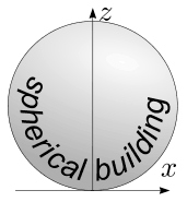
iii. (2.5 pts) What is the minimal launching speed \(v_{\min}\) needed to hit the topmost point of a spherical building of radius \(R\)?
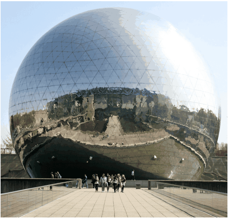
La Géode, Parc de la Villette, Paris. Photo: katchooo/flickr.com
Part B. Air flow around a wing (4 points)
For this part of the problem, the following information may be useful. For a flow of liquid or gas in a tube along a streamline, \(p+\rho gh+\frac12\rho v^2=\text{const.}\), assuming that the velocity \(v\) is much less than the speed of sound. Here \(\rho\) is the density, \(h\) is the height, \(g\) is free fall acceleration and \(p\) is hydrostatic pressure. Streamlines are defined as the trajectories of fluid particles (assuming that the flow pattern is stationary). Note that the term \(\frac12\rho v^2\) is called the dynamic pressure.
In the fig. shown below, a cross-section of an aircraft wing is depicted together with streamlines of the air flow around the wing, as seen in the wing’s reference frame. Assume that (a) the air flow is purely two-dimensional (i.e. that the velocity vectors of air lie in the plane of the figure); (b) the streamline pattern is independent of the aircraft speed; (c) there is no wind; (d) the dynamic pressure is much smaller than the atmospheric pressure, \(p_0=1.0\times10^5\,\mathrm{Pa}\).
You can use a ruler to take measurements from the fig. on the answer sheet.
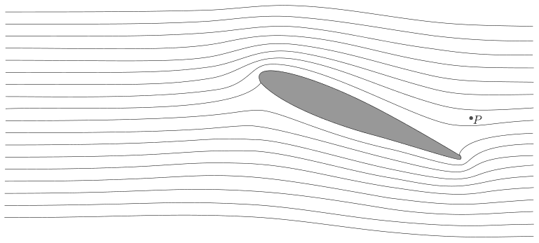
i. (0.8 pts) If the aircraft’s ground speed is \(v_0=100\,\mathrm{m/s}\), what is the speed of the air, \(v_P\), at the point \(P\) (marked in the fig.) with respect to the ground?
ii. (1.2 pts) In the case of high relative humidity, as the ground speed of the aircraft increases over a critical value \(v_{\mathrm{crit}}\), a stream of water droplets is created behind the wing. The droplets emerge at a certain point \(Q\). Mark the point \(Q\) in the fig. on the answer sheet. Explain qualitatively (using formulae and as little text as possible) how you determined the position of \(Q\).
iii. (2.0 pts) Estimate the critical speed \(v_{\mathrm{crit}}\) using the following data: relative humidity of the air is \(r=90\%\), specific heat capacity of air at constant pressure \(c_p=1.00\times10^3\,\mathrm{J/kg\cdot K}\), pressure of saturated water vapour: \(p_{sa}=2.31\,\mathrm{kPa}\) at the temperature of the unperturbed air \(T_a=293\,\mathrm K\) and \(p_{sb}=2.46\,\mathrm{kPa}\) at \(T_b=294\,\mathrm K\). Depending on your approximations, you may also need the specific heat capacity of air at constant volume \(c_V=0.717\times10^3\,\mathrm{J/kg\cdot K}\). Note that the relative humidity is defined as the ratio of the vapour pressure to the saturated vapour pressure at the given temperature. Saturated vapour pressure is defined as the vapour pressure by which vapour is in equilibrium with the liquid.
Part C. Magnetic straws (4.5 points)
Consider a cylindrical tube made of a superconducting material. The length of the tube is \(l\) and the inner radius is \(r\) with \(l\gg r\). The centre of the tube coincides with the origin, and its axis coincides with the \(z\)-axis.
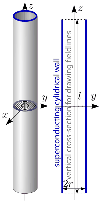
There is a magnetic flux \(\Phi\) through the central cross-section of the tube, \(z=0\), \(x^2+y^2<r^2\). A superconductor is a material which expels any magnetic field (the field is zero inside the material).
i. (0.8 pts) Sketch five such magnetic field lines, which pass through the five red dots marked on the axial cross-section of the tube, on the designated diagram on the answer sheet.
ii. (1.2 pts) Find the tension force \(T\) along the \(z\)-axis in the middle of the tube (i.e. the force by which two halves of the tube, \(z>0\) and \(z<0\), interact with each other).
iii. (2.5 pts) Consider another tube, identical and parallel to the first one.
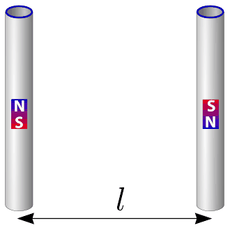
The second tube has the same magnetic field but in the opposite direction and its centre is placed at \(y=l\), \(x=z=0\) (so that the tubes form opposite sides of a square). Determine the magnetic interaction force \(F\) between the two tubes.
Official English text of the problem.
Answers
- A.i. \(\displaystyle z_0=\frac{v_0^2}{2g},\qquad k=\frac{g}{2v_0^2}.\)
- A.ii. The optimal parabola rises from the ground, grazes the upper side of the building tangentially, rises slightly farther, and then descends onto the topmost point. For approach from the left, its equation is \[ z=2R-\frac{x}{\sqrt3}-\frac{4x^2}{3R}. \]
- A.iii. \(\displaystyle \boxed{v_{\min}=3\sqrt{\frac{gR}{2}}}.\)
- B.i. \(\displaystyle \boxed{v_P\approx20\,\mathrm{m/s}}\), approximately in the aircraft’s direction of motion.
- B.ii. Place \(Q\) immediately above the rounded leading edge, where the streamlines on the upper side are closest together: the speed is greatest and the temperature lowest.
- B.iii. \(\displaystyle \boxed{v_{\mathrm{crit}}\approx35\,\mathrm{m/s}}\), using a maximum local speed about twice the aircraft speed and including the change in vapour partial pressure. Neglecting that pressure change gives approximately \(32\,\mathrm{m/s}\).
- C.i. Draw nearly parallel axial lines inside the bore. The four off-axis lines spread out beyond the ends and return around the outside, without entering the superconducting wall. The central axial line remains straight.
- C.ii. \(\displaystyle \boxed{T\simeq\frac{\Phi^2}{2\mu_0\pi r^2}}\), attracting the two halves.
- C.iii. The tubes attract with \[ \boxed{F\simeq\frac{\Phi^2}{4\pi\mu_0l^2} \left(2-\frac1{\sqrt2}\right)}. \] The magnetic results use the long, narrow tube approximation.
Solution
A.i.
For launch angle \(\theta\), eliminating time from projectile motion gives
\[ z=x\tan\theta-\frac{gx^2}{2v_0^2\cos^2\theta}. \]
Writing \(u=\tan\theta\),
\[ z=xu-\frac{gx^2}{2v_0^2}(1+u^2). \]
At fixed \(x\ne0\), this quadratic is maximized when
\[ u=\frac{v_0^2}{gx}. \]
Substitution gives the envelope
\[ z_{\mathrm{env}}=\frac{v_0^2}{2g}-\frac{gx^2}{2v_0^2}. \]
At \(x=0\), its height is also the maximum height of a vertical throw. Therefore,
\[ \boxed{z_0=\frac{v_0^2}{2g}},\qquad \boxed{k=\frac{g}{2v_0^2}}. \]
A.ii.
Put the centre of the building at \((0,R)\), so its top is \((0,2R)\). Choose a launch point to the left; reflection about the \(z\)-axis gives an equally good trajectory.
The required sketch is a downward-opening parabola with these features:
- It starts on the ground to the left of the building and rises steeply.
- It grazes the upper-left surface tangentially, with no change of velocity from an impact.
- It continues upward to an apex slightly above and to the left of the building’s top.
- It then descends to the topmost point.
The exact landmarks, derived below, are:
| Landmark | \(x/R\) | \(z/R\) |
|---|---|---|
| Launch | \(\displaystyle-\frac{\sqrt3+3\sqrt{11}}8\approx-1.460\) | \(0\) |
| Tangential grazing point | \(\displaystyle-\frac{\sqrt3}{2}\approx-0.866\) | \(\displaystyle\frac32\) |
| Apex | \(\displaystyle-\frac{\sqrt3}{8}\approx-0.217\) | \(\displaystyle\frac{33}{16}=2.0625\) |
| Target | \(0\) | \(2\) |
A.iii.
Let \(v_t\) be the speed when the ball reaches the target. Conservation of mechanical energy gives
\[ \frac12mv_0^2=\frac12mv_t^2+mg(2R), \]
so
\[ v_0^2=v_t^2+4gR. \]
Thus minimizing the launching speed is equivalent to minimizing \(v_t\).
Reverse the motion. We now launch a projectile from \((0,2R)\) with speed \(v_t\). By A.i, every such trajectory lies below the envelope
\[ z_{\mathrm{env}}(x) =2R+\frac{v_t^2}{2g}-\frac{gx^2}{2v_t^2}. \]
A trajectory approaching the target from the left must clear the upper surface
\[ z_s(x)=R+\sqrt{R^2-x^2}, \qquad -R\le x\le0. \]
Consequently, the envelope must also clear that surface.
Define
\[ \lambda=\frac{v_t^2}{gR}, \qquad c=\sqrt{1-\frac{x^2}{R^2}}, \qquad 0\le c\le1. \]
The difference between envelope and roof is
\[ \begin{aligned} \frac{z_{\mathrm{env}}-z_s}{R} &=1+\frac{\lambda}{2} -\frac{1-c^2}{2\lambda}-c\\ &=\frac{(c-\lambda)^2+2\lambda-1}{2\lambda}. \end{aligned} \]
If \(0<\lambda<1/2\), choosing \(c=\lambda\) makes this negative. No trajectory can then clear the building. Hence
\[ v_t^2\ge\frac{gR}{2}. \]
At equality, the envelope touches the roof at \(c=1/2\), namely
\[ (x,z)=\left(-\frac{\sqrt3}{2}R,\frac32R\right). \]
We must also show that one actual trajectory attains the bound. Launching the reversed projectile \(30^\circ\) above the horizontal towards the left gives, in the original coordinates,
\[ \boxed{z(x)=2R-\frac{x}{\sqrt3}-\frac{4x^2}{3R}}. \]
This parabola passes through the target and is tangent to the sphere at the point above. To verify that it never penetrates the building, set \(t=-x/R\ge0\). Direct substitution gives
\[ \frac{x^2+(z-R)^2-R^2}{R^2} = \frac{16}{9}\, t\left(t+\frac{\sqrt3}{2}\right) \left(t-\frac{\sqrt3}{2}\right)^2 \ge0. \]
Thus the entire relevant trajectory is outside the sphere, with tangential contact before the target. No bounce is needed.
Finally,
\[ v_{\min}^2=\frac{gR}{2}+4gR=\frac92gR, \]
and therefore
\[ \boxed{v_{\min}=3\sqrt{\frac{gR}{2}}}. \]
The intercept and apex of this parabola give the landmarks listed in A.ii.
B.i.
Let \(u\) denote air speed in the wing’s frame. Because the pressure changes are small compared with atmospheric pressure, we first treat the density as constant.
For a narrow stream tube of unit span, continuity gives
\[ u\,d=v_0d_\infty, \]
where \(d\) is the spacing between adjacent streamlines, measured perpendicular to the flow, and \(d_\infty\) is their undisturbed upstream spacing. Thus
\[ u=v_0\frac{d_\infty}{d}. \]
From the supplied figure, the spacing near \(P\) is approximately \(1.25\) times the upstream spacing:
\[ u_P\approx0.80v_0\approx80\,\mathrm{m/s}. \]
Take the undisturbed flow in the wing’s frame to point rightwards. The aircraft then moves leftwards relative to the ground, so the velocity transformation is
\[ \boldsymbol v_{P,\mathrm{ground}} =\boldsymbol u_P-v_0\hat{\boldsymbol x}. \]
The streamlines at \(P\) are nearly horizontal. Therefore,
\[ \boxed{v_P\approx|80-100| =20\,\mathrm{m/s}}, \]
approximately leftwards, in the aircraft’s direction of motion.
If the small local inclination is retained, the corresponding expression is
\[ v_P=\sqrt{u_P^2+v_0^2-2u_Pv_0\cos\theta_P}. \]
B.ii.
Neglect gravitational potential differences across the wing. Continuity and Bernoulli’s equation give
\[ u\propto\frac1d, \qquad p=p_0+\frac12\rho(v_0^2-u^2). \]
For approximately adiabatic flow, conservation of stagnation enthalpy gives
\[ c_pT+\frac{u^2}{2} =c_pT_a+\frac{v_0^2}{2}. \]
Hence
\[ d\ \text{smallest} \quad\Longrightarrow\quad u\ \text{largest} \quad\Longrightarrow\quad p,T\ \text{smallest}. \]
The saturation vapour pressure falls rapidly with temperature, so the relative humidity reaches unity first there.
Place \(Q\) just above the rounded leading edge, in the region of minimum streamline spacing on the upper side of the wing. The emerging droplets are subsequently carried downstream.
B.iii.
We model the air as an ideal gas undergoing approximately adiabatic, reversible expansion before condensation begins. Its specific gas constant is
\[ R_{\mathrm{air}}=c_p-c_V =283\,\mathrm{J\,kg^{-1}\,K^{-1}}. \]
Let the cooling at \(Q\) be \(\Delta T=T_a-T_Q>0\). The supplied saturation-pressure data give the local slope
\[ s=\frac{p_{sb}-p_{sa}}{T_b-T_a} =\frac{2460-2310}{294-293} =150\,\mathrm{Pa/K}. \]
Using a linear extrapolation,
\[ p_s(T_Q)\approx p_{sa}-s\Delta T. \]
Before condensation, the water-vapour mole fraction is unchanged, so its partial pressure scales with total pressure:
\[ p_{v,Q}=r p_{sa}\frac{p_Q}{p_0}. \]
The ideal-gas adiabatic relation gives
\[ \frac{p_Q}{p_0} =\left(\frac{T_Q}{T_a}\right)^{c_p/R_{\mathrm{air}}} \approx 1-\frac{c_p}{R_{\mathrm{air}}T_a}\Delta T. \]
At the onset of condensation, \(p_{v,Q}=p_s(T_Q)\). Therefore,
\[ r p_{sa} \left(1-\frac{c_p\Delta T}{R_{\mathrm{air}}T_a}\right) =p_{sa}-s\Delta T, \]
which yields
\[ \Delta T = \frac{(1-r)p_{sa}} {s-rp_{sa}c_p/(R_{\mathrm{air}}T_a)}. \]
Numerically,
\[ \Delta T = \frac{0.10(2310)} {150-\dfrac{0.90(2310)(1000)}{283(293)}} \approx1.85\,\mathrm K. \]
Thus condensation begins at approximately \(291.2\,\mathrm K\).
Let
\[ \alpha=\frac{u_Q}{v_0}\approx\frac{d_\infty}{d_Q}. \]
The narrowest spacing in the drawing is approximately half the undisturbed spacing, giving \(\alpha\approx2\). The energy equation then gives
\[ c_p\Delta T =\frac12(u_Q^2-v_{\mathrm{crit}}^2) =\frac12(\alpha^2-1)v_{\mathrm{crit}}^2. \]
Consequently,
\[ \boxed{ v_{\mathrm{crit}} =\sqrt{\frac{2c_p\Delta T}{\alpha^2-1}} \approx \sqrt{\frac{2(1000)(1.85)}{4-1}} \approx35\,\mathrm{m/s} }. \]
The corresponding pressure decrease is about \(2.2\%\), consistent with treating density changes as small for the graphical velocity estimate.
A simpler approximation holds the vapour partial pressure constant. It gives
\[ \Delta T\approx\frac{(1-r)p_{sa}}s=1.54\,\mathrm K, \qquad v_{\mathrm{crit}}\approx32\,\mathrm{m/s}. \]
Both estimates place the threshold at a few tens of metres per second; the pressure-corrected estimate is about \(35\,\mathrm{m/s}\).
C.i.
Choose the flux direction to be \(+z\) inside the tube; reversing every arrow gives the opposite convention.
Far from the ends, the field in the bore is nearly uniform and axial. Draw five nearly straight, parallel lines through the marked dots.
At the openings:
- The two off-axis lines on each side fan outward beyond the upper end, curve down around the exterior, and return through the lower opening.
- The pattern is symmetric about the axis and about the middle plane.
- Lines passing closer to the axis form larger exterior loops.
- No line crosses the superconducting wall; the field is tangent to its surfaces.
For the dot on the axis, axial symmetry requires a straight line along the \(z\)-axis. It extends to infinity in both directions; it has no finite endpoint. Arrows on the other lines point upward inside the bore and downward along their exterior return portions.
C.ii.
Write the bore area as
\[ A=\pi r^2. \]
Since \(l\gg r\), the central field is approximately uniform:
\[ B=\frac{\Phi}{A}. \]
The Maxwell stress along a magnetic field is tensile, with magnitude
\[ \sigma_\parallel=\frac{B^2}{2\mu_0}. \]
Integrating this stress over the central bore gives the attraction between the halves:
\[ T\simeq\frac{B^2A}{2\mu_0} =\boxed{\frac{\Phi^2}{2\mu_0\pi r^2}}. \]
The weak exterior return field produces a small correction in the long-tube limit.
The result also follows from magnetic energy. At fixed trapped flux and cross-section,
\[ U\simeq\frac{B^2}{2\mu_0}Al =\frac{\Phi^2l}{2\mu_0A}. \]
Increasing the tube’s length requires work \(T\,dl=dU\), giving the same tension.
C.iii.
At distances large compared with the tube radius, the flux emerging from an end behaves as the field of an effective magnetic pole. Its strength is
\[ q_m=\frac{\Phi}{\mu_0}, \]
because its radial field is
\[ B(s)=\frac{\mu_0q_m}{4\pi s^2} =\frac{\Phi}{4\pi s^2}. \]
These are equivalent sources for the exterior field; no actual magnetic monopoles are required. The two ends have opposite signs.
The force between two such effective poles separated by \(s\) has magnitude
\[ \frac{\mu_0q_m^2}{4\pi s^2} =\frac{\Phi^2}{4\pi\mu_0s^2}. \]
Set
\[ K=\frac{\Phi^2}{4\pi\mu_0}. \]
For the antiparallel tubes, all four end-to-end interactions must be included:
| End pairs | Separation | Interaction | Combined component towards the other tube |
|---|---|---|---|
| Upper–upper and lower–lower | \(l\) | Attraction | \(\displaystyle \frac{2K}{l^2}\) |
| Upper–lower and lower–upper | \(\sqrt2\,l\) | Repulsion | \(\displaystyle-\frac{K}{\sqrt2\,l^2}\) |
For each diagonal pair, the force magnitude is \(K/(2l^2)\), and its transverse component is this magnitude multiplied by \(\cos45^\circ\). Their vertical components cancel.
Therefore,
\[ \boxed{ F\simeq \frac{\Phi^2}{4\pi\mu_0l^2} \left(2-\frac1{\sqrt2}\right) }. \]
The force is attractive: it acts in the \(+y\) direction on the first tube and in the \(-y\) direction on the second.
The solution was checked against the official solution.
IPhO 2012 · Theorieaufgabe 1
Skizzen im Mittelpunkt
Aufgabe T1. Skizzen im Mittelpunkt (13 Punkte)
Teil A. Ballistik (4.5 Punkte)
Ein Ball, der mit einer Anfangsgeschwindigkeit \(v_0\) geworfen wird, bewegt sich in einem homogenen Gravitationsfeld in der \(x\)-\(z\)-Ebene. Dabei verläuft die \(x\)-Achse horizontal und die \(z\)-Achse vertikal und antiparallel zur Fallbeschleunigung \(g\). Vernachlässigen Sie den Luftwiderstand.
i. (0.8 Punkte) Durch Wahl des Abwurfwinkels eines Balls, der mit einer festen Anfangsgeschwindigkeit \(v_0\) vom Ursprung aus geworfen wird, lassen sich Ziele innerhalb des durch
\[ z\leq z_0-kx^2 \]
gegebenen Bereichs treffen. Sie dürfen diese Tatsache ohne Beweis verwenden. Bestimmen Sie die Konstanten \(z_0\) und \(k\).
ii. (1.2 Punkte) Der Abwurfpunkt kann nun auf Bodenhöhe \(z=0\) frei gewählt und der Abwurfwinkel nach Bedarf eingestellt werden. Ziel ist es, den höchsten Punkt eines kugelförmigen Gebäudes mit dem Radius \(R\) (siehe Abb.) mit der kleinstmöglichen Anfangsgeschwindigkeit \(v_0\) zu treffen. Ein Abprallen vom Dach vor dem Treffen des Ziels ist nicht zulässig. Skizzieren Sie qualitativ die Form der optimalen Flugbahn des Balls (verwenden Sie das dafür vorgesehene Feld auf dem Antwortbogen). Beachten Sie, dass nur die Skizze bewertet wird.
iii. (2.5 Punkte) Welche minimale Abwurfgeschwindigkeit \(v_{\min}\) ist erforderlich, um den höchsten Punkt eines kugelförmigen Gebäudes mit dem Radius \(R\) zu treffen?
La Géode, Parc de la Villette, Paris. Foto: katchooo/flickr.com
Teil B. Luftströmung um einen Tragflügel (4 Punkte)
Für diesen Teil der Aufgabe können die folgenden Informationen hilfreich sein. Für die Strömung einer Flüssigkeit oder eines Gases in einem Rohr gilt entlang einer Stromlinie \(p+\rho gh+\frac12\rho v^2=\text{konst.}\), sofern die Geschwindigkeit \(v\) viel kleiner als die Schallgeschwindigkeit ist. Hierbei sind \(\rho\) die Dichte, \(h\) die Höhe, \(g\) die Fallbeschleunigung und \(p\) der hydrostatische Druck. Stromlinien sind als die Bahnen der Fluidteilchen definiert (unter der Annahme, dass das Strömungsbild stationär ist). Beachten Sie, dass der Term \(\frac12\rho v^2\) als dynamischer Druck bezeichnet wird.
Die folgende Abbildung zeigt einen Querschnitt durch einen Flugzeugtragflügel zusammen mit den Stromlinien der Luftströmung um den Tragflügel, betrachtet im Bezugssystem des Tragflügels. Nehmen Sie an, dass (a) die Luftströmung rein zweidimensional ist (d. h., dass die Geschwindigkeitsvektoren der Luft in der Zeichenebene liegen); (b) das Stromlinienbild unabhängig von der Flugzeuggeschwindigkeit ist; (c) kein Wind herrscht; (d) der dynamische Druck viel kleiner als der atmosphärische Druck \(p_0=1.0\times10^5\,\mathrm{Pa}\) ist.
Sie dürfen mit einem Lineal Messungen an der Abbildung auf dem Antwortbogen vornehmen.
i. (0.8 Punkte) Wenn die Geschwindigkeit des Flugzeugs relativ zum Boden \(v_0=100\,\mathrm{m/s}\) beträgt, wie groß ist dann die Geschwindigkeit der Luft \(v_P\) am Punkt \(P\) (in der Abb. markiert) relativ zum Boden?
ii. (1.2 Punkte) Bei hoher relativer Luftfeuchtigkeit entsteht hinter dem Tragflügel ein Strom von Wassertröpfchen, sobald die Geschwindigkeit des Flugzeugs relativ zum Boden einen kritischen Wert \(v_{\mathrm{crit}}\) überschreitet. Die Tröpfchen entstehen an einem bestimmten Punkt \(Q\). Markieren Sie den Punkt \(Q\) in der Abbildung auf dem Antwortbogen. Erläutern Sie qualitativ (mit Formeln und möglichst wenig Text), wie Sie die Lage von \(Q\) bestimmt haben.
iii. (2.0 Punkte) Schätzen Sie die kritische Geschwindigkeit \(v_{\mathrm{crit}}\) anhand folgender Daten ab: relative Luftfeuchtigkeit \(r=90\%\), spezifische Wärmekapazität der Luft bei konstantem Druck \(c_p=1.00\times10^3\,\mathrm{J/kg\cdot K}\), Sättigungsdampfdruck von Wasser: \(p_{sa}=2.31\,\mathrm{kPa}\) bei der Temperatur der ungestörten Luft \(T_a=293\,\mathrm K\) und \(p_{sb}=2.46\,\mathrm{kPa}\) bei \(T_b=294\,\mathrm K\). Je nach Ihren Näherungen benötigen Sie möglicherweise auch die spezifische Wärmekapazität der Luft bei konstantem Volumen \(c_V=0.717\times10^3\,\mathrm{J/kg\cdot K}\). Beachten Sie, dass die relative Luftfeuchtigkeit als Verhältnis des Dampfdrucks zum Sättigungsdampfdruck bei der jeweiligen Temperatur definiert ist. Der Sättigungsdampfdruck ist der Dampfdruck, bei dem der Dampf mit der Flüssigkeit im Gleichgewicht steht.
Teil C. Magnetische Strohhalme (4.5 Punkte)
Betrachten Sie ein zylindrisches Rohr aus einem supraleitenden Material. Die Länge des Rohrs beträgt \(l\), sein Innenradius \(r\), wobei \(l\gg r\) gilt. Der Mittelpunkt des Rohrs liegt im Ursprung, und seine Achse fällt mit der \(z\)-Achse zusammen.
Durch den mittleren Querschnitt des Rohrs, \(z=0\), \(x^2+y^2<r^2\), tritt ein magnetischer Fluss \(\Phi\). Ein Supraleiter ist ein Material, das jedes Magnetfeld aus seinem Inneren verdrängt (im Material ist das Feld null).
i. (0.8 Punkte) Skizzieren Sie im dafür vorgesehenen Diagramm auf dem Antwortbogen fünf magnetische Feldlinien, die durch die fünf roten Punkte im Längsschnitt durch die Rohrachse verlaufen.
ii. (1.2 Punkte) Bestimmen Sie die Zugkraft \(T\) entlang der \(z\)-Achse in der Mitte des Rohrs (d. h. die Kraft, mit der die beiden Rohrhälften \(z>0\) und \(z<0\) aufeinander wirken).
iii. (2.5 Punkte) Betrachten Sie ein weiteres Rohr, das mit dem ersten identisch und parallel zu ihm ist.
Das zweite Rohr hat dasselbe Magnetfeld, jedoch in entgegengesetzter Richtung, und sein Mittelpunkt befindet sich bei \(y=l\), \(x=z=0\) (die Rohre bilden also gegenüberliegende Seiten eines Quadrats). Bestimmen Sie die magnetische Wechselwirkungskraft \(F\) zwischen den beiden Rohren.
Aufgabentext aus dem offiziellen englischen Text übersetzt.
Antworten
- A.i. \(\displaystyle z_0=\frac{v_0^2}{2g},\qquad k=\frac{g}{2v_0^2}.\)
- A.ii. Die optimale Parabel steigt vom Boden auf, streift die Oberseite des Gebäudes tangential, steigt noch etwas weiter an und fällt dann zum höchsten Punkt hin ab. Bei einer Annäherung von links lautet ihre Gleichung \[ z=2R-\frac{x}{\sqrt3}-\frac{4x^2}{3R}. \]
- A.iii. \(\displaystyle \boxed{v_{\min}=3\sqrt{\frac{gR}{2}}}.\)
- B.i. \(\displaystyle \boxed{v_P\approx20\,\mathrm{m/s}}\), ungefähr in Bewegungsrichtung des Flugzeugs.
- B.ii. Setzen Sie \(Q\) unmittelbar oberhalb der abgerundeten Vorderkante, wo die Stromlinien auf der Oberseite am dichtesten beieinanderliegen: Dort ist die Geschwindigkeit am größten und die Temperatur am niedrigsten.
- B.iii. \(\displaystyle \boxed{v_{\mathrm{crit}}\approx35\,\mathrm{m/s}}\), wenn man eine maximale lokale Geschwindigkeit von etwa dem Doppelten der Flugzeuggeschwindigkeit ansetzt und die Änderung des Wasserdampfpartialdrucks berücksichtigt. Vernachlässigt man diese Druckänderung, erhält man ungefähr \(32\,\mathrm{m/s}\).
- C.i. Zeichnen Sie im Rohrinneren nahezu parallele axiale Linien. Die vier außerhalb der Achse verlaufenden Linien fächern sich jenseits der Enden auf und laufen außen zurück, ohne in die supraleitende Wand einzutreten. Die mittlere axiale Linie bleibt gerade.
- C.ii. \(\displaystyle \boxed{T\simeq\frac{\Phi^2}{2\mu_0\pi r^2}}\), wobei sich die beiden Hälften anziehen.
- C.iii. Die Rohre ziehen sich mit \[ \boxed{F\simeq\frac{\Phi^2}{4\pi\mu_0l^2} \left(2-\frac1{\sqrt2}\right)} \] an. Die magnetischen Ergebnisse gelten in der Näherung eines langen, dünnen Rohrs.
Lösung
A.i.
Für den Abwurfwinkel \(\theta\) erhält man durch Eliminieren der Zeit aus der Wurfbewegung
\[ z=x\tan\theta-\frac{gx^2}{2v_0^2\cos^2\theta}. \]
Mit \(u=\tan\theta\) folgt
\[ z=xu-\frac{gx^2}{2v_0^2}(1+u^2). \]
Bei festem \(x\ne0\) wird diese quadratische Funktion maximal für
\[ u=\frac{v_0^2}{gx}. \]
Einsetzen ergibt die Einhüllende
\[ z_{\mathrm{env}}=\frac{v_0^2}{2g}-\frac{gx^2}{2v_0^2}. \]
Bei \(x=0\) entspricht ihre Höhe zugleich der maximalen Höhe eines senkrechten Wurfs. Daher gilt
\[ \boxed{z_0=\frac{v_0^2}{2g}},\qquad \boxed{k=\frac{g}{2v_0^2}}. \]
A.ii.
Wir legen den Mittelpunkt des Gebäudes nach \((0,R)\), sodass sein höchster Punkt bei \((0,2R)\) liegt. Wir wählen einen Abwurfpunkt links davon; Spiegelung an der \(z\)-Achse liefert eine ebenso geeignete Flugbahn.
Die gesuchte Skizze ist eine nach unten geöffnete Parabel mit folgenden Eigenschaften:
- Sie beginnt am Boden links vom Gebäude und steigt steil an.
- Sie streift die Oberfläche oben links tangential, ohne dass sich die Geschwindigkeit durch einen Stoß ändert.
- Sie steigt weiter bis zu einem Scheitelpunkt, der etwas oberhalb und links vom höchsten Punkt des Gebäudes liegt.
- Anschließend fällt sie zum höchsten Punkt hin ab.
Die unten hergeleiteten exakten charakteristischen Punkte sind:
| Charakteristischer Punkt | \(x/R\) | \(z/R\) |
|---|---|---|
| Abwurfpunkt | \(\displaystyle-\frac{\sqrt3+3\sqrt{11}}8\approx-1.460\) | \(0\) |
| Tangentialer Berührpunkt | \(\displaystyle-\frac{\sqrt3}{2}\approx-0.866\) | \(\displaystyle\frac32\) |
| Scheitelpunkt | \(\displaystyle-\frac{\sqrt3}{8}\approx-0.217\) | \(\displaystyle\frac{33}{16}=2.0625\) |
| Ziel | \(0\) | \(2\) |
A.iii.
Sei \(v_t\) die Geschwindigkeit, mit der der Ball das Ziel erreicht. Aus der Erhaltung der mechanischen Energie folgt
\[ \frac12mv_0^2=\frac12mv_t^2+mg(2R), \]
also
\[ v_0^2=v_t^2+4gR. \]
Die Minimierung der Abwurfgeschwindigkeit ist somit gleichbedeutend mit der Minimierung von \(v_t\).
Wir kehren die Bewegung um. Nun werfen wir einen Körper von \((0,2R)\) aus mit der Geschwindigkeit \(v_t\) ab. Nach A.i liegt jede solche Flugbahn unterhalb der Einhüllenden
\[ z_{\mathrm{env}}(x) =2R+\frac{v_t^2}{2g}-\frac{gx^2}{2v_t^2}. \]
Eine Flugbahn, die sich dem Ziel von links nähert, muss die folgende obere Oberfläche überwinden:
\[ z_s(x)=R+\sqrt{R^2-x^2}, \qquad -R\le x\le0. \]
Folglich darf auch die Einhüllende diese Oberfläche nicht unterschreiten.
Wir definieren
\[ \lambda=\frac{v_t^2}{gR}, \qquad c=\sqrt{1-\frac{x^2}{R^2}}, \qquad 0\le c\le1. \]
Die Differenz zwischen Einhüllender und Dach ist
\[ \begin{aligned} \frac{z_{\mathrm{env}}-z_s}{R} &=1+\frac{\lambda}{2} -\frac{1-c^2}{2\lambda}-c\\ &=\frac{(c-\lambda)^2+2\lambda-1}{2\lambda}. \end{aligned} \]
Für \(0<\lambda<1/2\) wird dieser Ausdruck bei der Wahl \(c=\lambda\) negativ. Dann kann keine Flugbahn das Gebäude überwinden. Daher gilt
\[ v_t^2\ge\frac{gR}{2}. \]
Im Gleichheitsfall berührt die Einhüllende das Dach bei \(c=1/2\), also bei
\[ (x,z)=\left(-\frac{\sqrt3}{2}R,\frac32R\right). \]
Wir müssen außerdem zeigen, dass eine tatsächliche Flugbahn diese Schranke erreicht. Wird der Körper bei umgekehrter Bewegung unter einem Winkel von \(30^\circ\) über der Horizontalen nach links abgeworfen, so ergibt sich in den ursprünglichen Koordinaten
\[ \boxed{z(x)=2R-\frac{x}{\sqrt3}-\frac{4x^2}{3R}}. \]
Diese Parabel verläuft durch das Ziel und berührt die Kugel im oben genannten Punkt tangential. Um zu überprüfen, dass sie nirgends in das Gebäude eindringt, setzen wir \(t=-x/R\ge0\). Direktes Einsetzen ergibt
\[ \frac{x^2+(z-R)^2-R^2}{R^2} = \frac{16}{9}\, t\left(t+\frac{\sqrt3}{2}\right) \left(t-\frac{\sqrt3}{2}\right)^2 \ge0. \]
Somit liegt die gesamte relevante Flugbahn außerhalb der Kugel und berührt sie vor dem Erreichen des Ziels tangential. Ein Abprallen ist nicht erforderlich.
Schließlich gilt
\[ v_{\min}^2=\frac{gR}{2}+4gR=\frac92gR, \]
und damit
\[ \boxed{v_{\min}=3\sqrt{\frac{gR}{2}}}. \]
Der Schnittpunkt dieser Parabel mit dem Boden und ihr Scheitelpunkt ergeben die in A.ii aufgeführten charakteristischen Punkte.
B.i.
Mit \(u\) bezeichnen wir die Luftgeschwindigkeit im Bezugssystem des Tragflügels. Da die Druckänderungen gegenüber dem atmosphärischen Druck klein sind, behandeln wir die Dichte zunächst als konstant.
Für eine schmale Stromröhre mit Einheitsbreite in Spannweitenrichtung ergibt die Kontinuitätsgleichung
\[ u\,d=v_0d_\infty, \]
wobei \(d\) der senkrecht zur Strömung gemessene Abstand benachbarter Stromlinien und \(d_\infty\) ihr ungestörter Abstand stromaufwärts ist. Somit gilt
\[ u=v_0\frac{d_\infty}{d}. \]
Aus der vorgegebenen Abbildung ergibt sich, dass der Abstand nahe \(P\) etwa das \(1.25\)-Fache des Abstands stromaufwärts beträgt:
\[ u_P\approx0.80v_0\approx80\,\mathrm{m/s}. \]
Wir nehmen an, dass die ungestörte Strömung im Bezugssystem des Tragflügels nach rechts gerichtet ist. Das Flugzeug bewegt sich dann relativ zum Boden nach links, sodass die Geschwindigkeitstransformation lautet:
\[ \boldsymbol v_{P,\mathrm{ground}} =\boldsymbol u_P-v_0\hat{\boldsymbol x}. \]
Die Stromlinien bei \(P\) verlaufen nahezu horizontal. Daher gilt
\[ \boxed{v_P\approx|80-100| =20\,\mathrm{m/s}}, \]
ungefähr nach links, in Bewegungsrichtung des Flugzeugs.
Berücksichtigt man die geringe lokale Neigung, lautet der entsprechende Ausdruck
\[ v_P=\sqrt{u_P^2+v_0^2-2u_Pv_0\cos\theta_P}. \]
B.ii.
Wir vernachlässigen Unterschiede des Gravitationspotentials über den Tragflügel hinweg. Kontinuitätsgleichung und Bernoulli-Gleichung liefern
\[ u\propto\frac1d, \qquad p=p_0+\frac12\rho(v_0^2-u^2). \]
Für eine näherungsweise adiabatische Strömung ergibt die Erhaltung der Totalenthalpie
\[ c_pT+\frac{u^2}{2} =c_pT_a+\frac{v_0^2}{2}. \]
Damit gilt
\[ d\ \text{am kleinsten} \quad\Longrightarrow\quad u\ \text{am größten} \quad\Longrightarrow\quad p,T\ \text{am kleinsten}. \]
Der Sättigungsdampfdruck nimmt mit sinkender Temperatur rasch ab, sodass die relative Luftfeuchtigkeit dort zuerst den Wert eins erreicht.
Setzen Sie \(Q\) unmittelbar oberhalb der abgerundeten Vorderkante in den Bereich des geringsten Stromlinienabstands auf der Oberseite des Tragflügels. Die entstehenden Tröpfchen werden anschließend stromabwärts mitgeführt.
B.iii.
Wir modellieren die Luft als ideales Gas, das vor Beginn der Kondensation eine näherungsweise adiabatische, reversible Expansion durchläuft. Seine spezifische Gaskonstante beträgt
\[ R_{\mathrm{air}}=c_p-c_V =283\,\mathrm{J\,kg^{-1}\,K^{-1}}. \]
Die Abkühlung bei \(Q\) sei \(\Delta T=T_a-T_Q>0\). Aus den angegebenen Sättigungsdampfdruckdaten ergibt sich die lokale Steigung
\[ s=\frac{p_{sb}-p_{sa}}{T_b-T_a} =\frac{2460-2310}{294-293} =150\,\mathrm{Pa/K}. \]
Mit einer linearen Extrapolation gilt
\[ p_s(T_Q)\approx p_{sa}-s\Delta T. \]
Vor der Kondensation bleibt der Stoffmengenanteil des Wasserdampfs unverändert, sodass sein Partialdruck proportional zum Gesamtdruck ist:
\[ p_{v,Q}=r p_{sa}\frac{p_Q}{p_0}. \]
Die Adiabatengleichung für ein ideales Gas liefert
\[ \frac{p_Q}{p_0} =\left(\frac{T_Q}{T_a}\right)^{c_p/R_{\mathrm{air}}} \approx 1-\frac{c_p}{R_{\mathrm{air}}T_a}\Delta T. \]
Zu Beginn der Kondensation gilt \(p_{v,Q}=p_s(T_Q)\). Daher ist
\[ r p_{sa} \left(1-\frac{c_p\Delta T}{R_{\mathrm{air}}T_a}\right) =p_{sa}-s\Delta T, \]
woraus folgt:
\[ \Delta T = \frac{(1-r)p_{sa}} {s-rp_{sa}c_p/(R_{\mathrm{air}}T_a)}. \]
Numerisch ergibt sich
\[ \Delta T = \frac{0.10(2310)} {150-\dfrac{0.90(2310)(1000)}{283(293)}} \approx1.85\,\mathrm K. \]
Die Kondensation beginnt somit bei ungefähr \(291.2\,\mathrm K\).
Es sei
\[ \alpha=\frac{u_Q}{v_0}\approx\frac{d_\infty}{d_Q}. \]
Der geringste Abstand in der Zeichnung beträgt etwa die Hälfte des ungestörten Abstands, sodass \(\alpha\approx2\) gilt. Aus der Energiegleichung folgt dann
\[ c_p\Delta T =\frac12(u_Q^2-v_{\mathrm{crit}}^2) =\frac12(\alpha^2-1)v_{\mathrm{crit}}^2. \]
Folglich gilt
\[ \boxed{ v_{\mathrm{crit}} =\sqrt{\frac{2c_p\Delta T}{\alpha^2-1}} \approx \sqrt{\frac{2(1000)(1.85)}{4-1}} \approx35\,\mathrm{m/s} }. \]
Die zugehörige Druckabnahme beträgt etwa \(2.2\%\), was mit der Annahme kleiner Dichteänderungen bei der grafischen Abschätzung der Geschwindigkeit vereinbar ist.
Eine einfachere Näherung hält den Wasserdampfpartialdruck konstant. Sie ergibt
\[ \Delta T\approx\frac{(1-r)p_{sa}}s=1.54\,\mathrm K, \qquad v_{\mathrm{crit}}\approx32\,\mathrm{m/s}. \]
Beide Abschätzungen ergeben einen Schwellenwert von einigen zehn Metern pro Sekunde; die um die Druckänderung korrigierte Abschätzung beträgt etwa \(35\,\mathrm{m/s}\).
C.i.
Wir wählen die Flussrichtung im Rohrinneren als \(+z\); durch Umkehren aller Pfeile erhält man die entgegengesetzte Konvention.
Weit von den Enden entfernt ist das Feld im Rohrinneren nahezu homogen und axial. Zeichnen Sie fünf nahezu gerade, parallele Linien durch die markierten Punkte.
An den Öffnungen:
- Die beiden außerhalb der Achse verlaufenden Linien auf jeder Seite fächern sich jenseits des oberen Endes nach außen auf, krümmen sich außen nach unten und kehren durch die untere Öffnung zurück.
- Das Muster ist symmetrisch bezüglich der Achse und der Mittelebene.
- Linien, die näher an der Achse verlaufen, bilden größere äußere Schleifen.
- Keine Linie durchquert die supraleitende Wand; das Feld verläuft tangential zu ihren Oberflächen.
Für den Punkt auf der Achse verlangt die Axialsymmetrie eine gerade Linie entlang der \(z\)-Achse. Sie erstreckt sich in beide Richtungen bis ins Unendliche und hat keinen endlichen Endpunkt. Die Pfeile auf den anderen Linien zeigen im Rohrinneren nach oben und auf den äußeren Rückwegen nach unten.
C.ii.
Wir schreiben die innere Querschnittsfläche als
\[ A=\pi r^2. \]
Da \(l\gg r\) gilt, ist das Feld in der Mitte näherungsweise homogen:
\[ B=\frac{\Phi}{A}. \]
Die Maxwell-Spannung entlang eines Magnetfelds ist eine Zugspannung mit dem Betrag
\[ \sigma_\parallel=\frac{B^2}{2\mu_0}. \]
Die Integration dieser Spannung über den inneren Querschnitt in der Rohrmitte ergibt die Anziehungskraft zwischen den Hälften:
\[ T\simeq\frac{B^2A}{2\mu_0} =\boxed{\frac{\Phi^2}{2\mu_0\pi r^2}}. \]
Das schwache äußere Rückfeld verursacht im Grenzfall eines langen Rohrs eine kleine Korrektur.
Das Ergebnis folgt auch aus der magnetischen Energie. Bei festem eingeschlossenem Fluss und festem Querschnitt gilt
\[ U\simeq\frac{B^2}{2\mu_0}Al =\frac{\Phi^2l}{2\mu_0A}. \]
Eine Vergrößerung der Rohrlänge erfordert die Arbeit \(T\,dl=dU\), woraus dieselbe Zugkraft folgt.
C.iii.
In Abständen, die groß gegenüber dem Rohrradius sind, verhält sich der aus einem Ende austretende Fluss wie das Feld eines effektiven magnetischen Pols. Seine Polstärke beträgt
\[ q_m=\frac{\Phi}{\mu_0}, \]
denn sein radiales Feld ist
\[ B(s)=\frac{\mu_0q_m}{4\pi s^2} =\frac{\Phi}{4\pi s^2}. \]
Dies sind Ersatzquellen für das äußere Feld; tatsächliche magnetische Monopole sind nicht erforderlich. Die beiden Enden haben entgegengesetzte Vorzeichen.
Die Kraft zwischen zwei solchen effektiven Polen im Abstand \(s\) hat den Betrag
\[ \frac{\mu_0q_m^2}{4\pi s^2} =\frac{\Phi^2}{4\pi\mu_0s^2}. \]
Wir setzen
\[ K=\frac{\Phi^2}{4\pi\mu_0}. \]
Bei den antiparallelen Rohren müssen alle vier Wechselwirkungen zwischen den Enden berücksichtigt werden:
| Endpaare | Abstand | Wechselwirkung | Gesamte Komponente zum anderen Rohr hin |
|---|---|---|---|
| Oben–oben und unten–unten | \(l\) | Anziehung | \(\displaystyle \frac{2K}{l^2}\) |
| Oben–unten und unten–oben | \(\sqrt2\,l\) | Abstoßung | \(\displaystyle-\frac{K}{\sqrt2\,l^2}\) |
Für jedes diagonale Paar beträgt die Kraft \(K/(2l^2)\), und ihre Querkomponente ergibt sich durch Multiplikation dieses Betrags mit \(\cos45^\circ\). Ihre vertikalen Komponenten heben sich auf.
Daher gilt
\[ \boxed{ F\simeq \frac{\Phi^2}{4\pi\mu_0l^2} \left(2-\frac1{\sqrt2}\right) }. \]
Die Kraft ist anziehend: Auf das erste Rohr wirkt sie in \(+y\)-Richtung, auf das zweite in \(-y\)-Richtung.
Die Lösung wurde mit der offiziellen Lösung abgeglichen.
IPhO 2012 · Teori sorusu 1
Çizimlere odaklanın
Soru T1. Çizimlere odaklanın (13 puan)
Bölüm A. Balistik (4.5 puan)
İlk hızı \(v_0\) olan bir top, homojen bir kütleçekim alanında, \(x\)-ekseni yatay ve \(z\)-ekseni düşey olup serbest düşme ivmesi \(g\) ile zıt yönde olacak şekilde, \(x\)-\(z\) düzleminde hareket etmektedir. Hava direncinin etkisini ihmal edin.
i. (0.8 puan) Orijinden sabit bir \(v_0\) ilk hızıyla atılan topun atış açısı ayarlanarak,
\[ z\leq z_0-kx^2. \]
ile verilen bölge içindeki hedefler vurulabilir. Bu bilgiyi kanıtlamadan kullanabilirsiniz. \(z_0\) ve \(k\) sabitlerini bulun.
ii. (1.2 puan) Artık atış noktası \(z=0\) yer seviyesinde serbestçe seçilebilmekte ve atış açısı gerektiği gibi ayarlanabilmektedir. Amaç, \(R\) yarıçaplı küresel bir binanın (şekle bakınız) en üst noktasını en küçük \(v_0\) ilk hızıyla vurmaktır. Hedefi vurmadan önce çatıdan sekmeye izin verilmemektedir. Topun en uygun yörüngesinin biçimini nitel olarak çizin (cevap kâğıdında ayrılan kutuyu kullanın). Puanların yalnızca çizime verileceğine dikkat edin.
iii. (2.5 puan) \(R\) yarıçaplı küresel bir binanın en üst noktasını vurmak için gereken en küçük atış hızı \(v_{\min}\) nedir?
La Géode, Parc de la Villette, Paris. Fotoğraf: katchooo/flickr.com
Bölüm B. Bir kanat çevresindeki hava akışı (4 puan)
Sorunun bu bölümünde aşağıdaki bilgiler yararlı olabilir. Bir boruda bir akım çizgisi boyunca akan sıvı veya gaz için, \(v\) hızının ses hızından çok daha küçük olduğu varsayımıyla, \(p+\rho gh+\frac12\rho v^2=\text{sabit}\) bağıntısı geçerlidir. Burada \(\rho\) yoğunluk, \(h\) yükseklik, \(g\) serbest düşme ivmesi ve \(p\) hidrostatik basınçtır. Akım çizgileri, akış deseninin zamana göre değişmediği varsayımı altında, akışkan parçacıklarının yörüngeleri olarak tanımlanır. \(\frac12\rho v^2\) teriminin dinamik basınç olarak adlandırıldığına dikkat edin.
Aşağıdaki şekilde, bir uçak kanadının kesiti, kanadın referans sisteminden görüldüğü hâliyle kanadın çevresindeki hava akışının akım çizgileriyle birlikte gösterilmiştir. Şunları varsayın: (a) hava akışı tamamen iki boyutludur (yani havanın hız vektörleri şeklin düzleminde yer alır); (b) akım çizgilerinin deseni uçağın hızından bağımsızdır; (c) rüzgâr yoktur; (d) dinamik basınç, atmosfer basıncı \(p_0=1.0\times10^5\,\mathrm{Pa}\) değerinden çok daha küçüktür.
Cevap kâğıdındaki şekilden ölçüm yapmak için cetvel kullanabilirsiniz.
i. (0.8 puan) Uçağın yere göre hızı \(v_0=100\,\mathrm{m/s}\) ise, şekilde işaretlenmiş \(P\) noktasındaki havanın yere göre hızı \(v_P\) nedir?
ii. (1.2 puan) Bağıl nemin yüksek olduğu durumda, uçağın yere göre hızı bir \(v_{\mathrm{crit}}\) kritik değerini aştığında, kanadın arkasında su damlacıklarından oluşan bir akım meydana gelir. Damlacıklar belirli bir \(Q\) noktasında ortaya çıkar. Cevap kâğıdındaki şekilde \(Q\) noktasını işaretleyin. \(Q\) noktasının yerini nasıl belirlediğinizi nitel olarak açıklayın (formüller ve mümkün olduğunca az metin kullanın).
iii. (2.0 puan) Aşağıdaki verileri kullanarak \(v_{\mathrm{crit}}\) kritik hızını tahmin edin: havanın bağıl nemi \(r=90\%\), havanın sabit basınçtaki özgül ısı kapasitesi \(c_p=1.00\times10^3\,\mathrm{J/kg\cdot K}\), doymuş su buharı basıncı, bozulmamış havanın sıcaklığı olan \(T_a=293\,\mathrm K\) sıcaklığında \(p_{sa}=2.31\,\mathrm{kPa}\) ve \(T_b=294\,\mathrm K\) sıcaklığında \(p_{sb}=2.46\,\mathrm{kPa}\). Yaptığınız yaklaşıklıklara bağlı olarak, havanın sabit hacimdeki özgül ısı kapasitesi \(c_V=0.717\times10^3\,\mathrm{J/kg\cdot K}\) değerine de ihtiyaç duyabilirsiniz. Bağıl nemin, verilen sıcaklıkta buhar basıncının doymuş buhar basıncına oranı olarak tanımlandığına dikkat edin. Doymuş buhar basıncı, buharın sıvıyla dengede olduğu buhar basıncı olarak tanımlanır.
Bölüm C. Manyetik pipetler (4.5 puan)
Süperiletken bir malzemeden yapılmış silindirik bir boruyu ele alın. Borunun uzunluğu \(l\), iç yarıçapı \(r\) olup \(l\gg r\) koşulu sağlanmaktadır. Borunun merkezi orijinle, ekseni ise \(z\)-ekseniyle çakışmaktadır.
Borunun \(z=0\), \(x^2+y^2<r^2\) ile tanımlanan orta kesitinden geçen bir \(\Phi\) manyetik akısı vardır. Süperiletken, her türlü manyetik alanı dışlayan bir malzemedir (malzemenin içinde alan sıfırdır).
i. (0.8 puan) Cevap kâğıdında ayrılan diyagram üzerinde, borunun eksenel kesitinde işaretlenmiş beş kırmızı noktadan geçen beş manyetik alan çizgisi çizin.
ii. (1.2 puan) Borunun ortasında, \(z\)-ekseni doğrultusundaki \(T\) gerilme kuvvetini (yani borunun \(z>0\) ve \(z<0\) yarılarının birbirlerine uyguladığı kuvveti) bulun.
iii. (2.5 puan) Birinci boruyla özdeş ve ona paralel başka bir boruyu ele alın.
İkinci boru aynı manyetik alana, ancak zıt yönde sahiptir ve merkezi \(y=l\), \(x=z=0\) konumundadır (böylece borular bir karenin karşılıklı kenarlarını oluşturur). İki boru arasındaki manyetik etkileşim kuvveti \(F\)'yi belirleyin.
Soru metni resmi İngilizce metinden çevrilmiştir.
Cevaplar
- A.i. \(\displaystyle z_0=\frac{v_0^2}{2g},\qquad k=\frac{g}{2v_0^2}.\)
- A.ii. En uygun parabol yerden yükselir, binanın üst tarafına teğet olarak değer, biraz daha yükselir ve ardından en üst noktaya doğru alçalır. Soldan yaklaşma durumunda denklemi \[ z=2R-\frac{x}{\sqrt3}-\frac{4x^2}{3R}. \] biçimindedir.
- A.iii. \(\displaystyle \boxed{v_{\min}=3\sqrt{\frac{gR}{2}}}.\)
- B.i. \(\displaystyle \boxed{v_P\approx20\,\mathrm{m/s}}\), yaklaşık olarak uçağın hareket yönündedir.
- B.ii. \(Q\)'yu yuvarlatılmış hücum kenarının hemen üstüne, üst taraftaki akım çizgilerinin birbirine en yakın olduğu yere yerleştirin: hız burada en büyük, sıcaklık ise en küçüktür.
- B.iii. En büyük yerel hızın uçak hızının yaklaşık iki katı olduğu kullanılarak ve buharın kısmi basıncındaki değişim hesaba katılarak \(\displaystyle \boxed{v_{\mathrm{crit}}\approx35\,\mathrm{m/s}}\) bulunur. Bu basınç değişimi ihmal edilirse yaklaşık \(32\,\mathrm{m/s}\) elde edilir.
- C.i. Borunun iç boşluğunda eksene paralel, neredeyse birbirine paralel çizgiler çizin. Eksen dışındaki dört çizgi, uçların ötesinde açılır ve süperiletken duvara girmeden dışarıdan dolanarak geri döner. Eksendeki merkez çizgi düz kalır.
- C.ii. \(\displaystyle \boxed{T\simeq\frac{\Phi^2}{2\mu_0\pi r^2}}\), iki yarıyı birbirine çeker.
- C.iii. Borular birbirini \[ \boxed{F\simeq\frac{\Phi^2}{4\pi\mu_0l^2} \left(2-\frac1{\sqrt2}\right)}. \] kuvvetiyle çeker. Manyetik sonuçlarda uzun ve dar boru yaklaşımı kullanılmıştır.
Çözüm
A.i.
Atış açısı \(\theta\) için, eğik atış hareketinden zaman elendiğinde
\[ z=x\tan\theta-\frac{gx^2}{2v_0^2\cos^2\theta}. \]
elde edilir. \(u=\tan\theta\) yazılırsa,
\[ z=xu-\frac{gx^2}{2v_0^2}(1+u^2). \]
Sabit bir \(x\ne0\) için bu ikinci dereceden ifade,
\[ u=\frac{v_0^2}{gx}. \]
olduğunda en büyük değerini alır. Yerine koyma işlemiyle zarf eğrisi
\[ z_{\mathrm{env}}=\frac{v_0^2}{2g}-\frac{gx^2}{2v_0^2}. \]
olarak bulunur. \(x=0\) noktasındaki yüksekliği, aynı zamanda düşey atışın en büyük yüksekliğidir. Dolayısıyla,
\[ \boxed{z_0=\frac{v_0^2}{2g}},\qquad \boxed{k=\frac{g}{2v_0^2}}. \]
A.ii.
Binanın merkezini \((0,R)\) noktasına yerleştirelim; böylece tepesi \((0,2R)\) olur. Solda bir atış noktası seçelim; \(z\)-eksenine göre yansıtma, aynı derecede iyi bir yörünge verir.
İstenen çizim, aşağıdaki özelliklere sahip, aşağı doğru açılan bir paraboldür:
- Binanın solunda, yerden başlar ve dik bir biçimde yükselir.
- Sol üst yüzeye teğet olarak değer; bir çarpma nedeniyle hızında değişiklik olmaz.
- Binanın tepesinin biraz üstünde ve solunda bulunan bir doruk noktasına kadar yükselmeye devam eder.
- Ardından en üst noktaya doğru alçalır.
Aşağıda türetilen önemli noktaların tam konumları şunlardır:
| Önemli nokta | \(x/R\) | \(z/R\) |
|---|---|---|
| Atış noktası | \(\displaystyle-\frac{\sqrt3+3\sqrt{11}}8\approx-1.460\) | \(0\) |
| Teğet temas noktası | \(\displaystyle-\frac{\sqrt3}{2}\approx-0.866\) | \(\displaystyle\frac32\) |
| Doruk noktası | \(\displaystyle-\frac{\sqrt3}{8}\approx-0.217\) | \(\displaystyle\frac{33}{16}=2.0625\) |
| Hedef | \(0\) | \(2\) |
A.iii.
Top hedefe ulaştığında hızının büyüklüğü \(v_t\) olsun. Mekanik enerjinin korunumu
\[ \frac12mv_0^2=\frac12mv_t^2+mg(2R), \]
bağıntısını verir; buradan
\[ v_0^2=v_t^2+4gR. \]
elde edilir. Dolayısıyla atış hızını en küçük yapmak, \(v_t\)'yi en küçük yapmakla eşdeğerdir.
Hareketi tersine çevirelim. Şimdi \((0,2R)\) noktasından \(v_t\) hızıyla bir cisim atıyoruz. A.i'ye göre bu tür her yörünge,
\[ z_{\mathrm{env}}(x) =2R+\frac{v_t^2}{2g}-\frac{gx^2}{2v_t^2}. \]
zarf eğrisinin altında kalır. Hedefe soldan yaklaşan bir yörünge,
\[ z_s(x)=R+\sqrt{R^2-x^2}, \qquad -R\le x\le0. \]
üst yüzeyinin üzerinden geçmelidir. Bu nedenle zarf eğrisi de bu yüzeyin üzerinden geçmelidir.
Şu tanımları yapalım:
\[ \lambda=\frac{v_t^2}{gR}, \qquad c=\sqrt{1-\frac{x^2}{R^2}}, \qquad 0\le c\le1. \]
Zarf eğrisi ile çatı arasındaki fark
\[ \begin{aligned} \frac{z_{\mathrm{env}}-z_s}{R} &=1+\frac{\lambda}{2} -\frac{1-c^2}{2\lambda}-c\\ &=\frac{(c-\lambda)^2+2\lambda-1}{2\lambda}. \end{aligned} \]
olur. \(0<\lambda<1/2\) ise, \(c=\lambda\) seçimi bu ifadeyi negatif yapar. Bu durumda hiçbir yörünge binanın üzerinden geçemez. O hâlde
\[ v_t^2\ge\frac{gR}{2}. \]
Eşitlik durumunda zarf eğrisi çatıya \(c=1/2\) değerinde, yani
\[ (x,z)=\left(-\frac{\sqrt3}{2}R,\frac32R\right). \]
noktasında değer.
Gerçek bir yörüngenin bu sınıra ulaştığını da göstermeliyiz. Tersine çevrilmiş harekette cismi sola doğru, yatayın \(30^\circ\) üstünde atmak, başlangıçtaki koordinatlarda
\[ \boxed{z(x)=2R-\frac{x}{\sqrt3}-\frac{4x^2}{3R}}. \]
yörüngesini verir.
Bu parabol hedeften geçer ve yukarıdaki noktada küreye teğettir. Binanın içine hiçbir zaman girmediğini doğrulamak için \(t=-x/R\ge0\) alalım. Doğrudan yerine koyarak
\[ \frac{x^2+(z-R)^2-R^2}{R^2} = \frac{16}{9}\, t\left(t+\frac{\sqrt3}{2}\right) \left(t-\frac{\sqrt3}{2}\right)^2 \ge0. \]
elde edilir. Böylece yörüngenin ilgili kısmının tamamı kürenin dışındadır ve hedefe varmadan önce teğet temas gerçekleşir. Sekmeye gerek yoktur.
Son olarak,
\[ v_{\min}^2=\frac{gR}{2}+4gR=\frac92gR, \]
ve dolayısıyla
\[ \boxed{v_{\min}=3\sqrt{\frac{gR}{2}}}. \]
Bu parabolün yerle kesişimi ve doruk noktası, A.ii'de listelenen önemli noktaları verir.
B.i.
\(u\), kanadın referans sistemindeki hava hızını göstersin. Basınç değişimleri atmosfer basıncına kıyasla küçük olduğundan, önce yoğunluğu sabit kabul ederiz.
Açıklığı bir birim olan dar bir akım tüpü için süreklilik denklemi
\[ u\,d=v_0d_\infty, \]
bağıntısını verir; burada \(d\), komşu akım çizgileri arasındaki akışa dik ölçülen uzaklık, \(d_\infty\) ise akışın bozulmadığı akış yukarısı bölgesinde bu çizgiler arasındaki uzaklıktır. Böylece
\[ u=v_0\frac{d_\infty}{d}. \]
Verilen şekle göre, \(P\) yakınındaki aralık akış yukarısındaki aralığın yaklaşık \(1.25\) katıdır:
\[ u_P\approx0.80v_0\approx80\,\mathrm{m/s}. \]
Kanadın referans sistemindeki bozulmamış akışın sağa doğru olduğunu kabul edelim. Bu durumda uçak yere göre sola doğru hareket eder; dolayısıyla hız dönüşümü
\[ \boldsymbol v_{P,\mathrm{ground}} =\boldsymbol u_P-v_0\hat{\boldsymbol x}. \]
olur. \(P\) noktasındaki akım çizgileri neredeyse yataydır. Bu nedenle,
\[ \boxed{v_P\approx|80-100| =20\,\mathrm{m/s}}, \]
yaklaşık olarak sola, uçağın hareket yönüne doğrudur.
Küçük yerel eğim hesaba katılırsa, buna karşılık gelen ifade
\[ v_P=\sqrt{u_P^2+v_0^2-2u_Pv_0\cos\theta_P}. \]
olur.
B.ii.
Kanat boyunca kütleçekim potansiyeli farklarını ihmal edelim. Süreklilik ve Bernoulli denklemleri
\[ u\propto\frac1d, \qquad p=p_0+\frac12\rho(v_0^2-u^2). \]
bağıntılarını verir.
Yaklaşık olarak adyabatik akış için durma entalpisinin korunumu
\[ c_pT+\frac{u^2}{2} =c_pT_a+\frac{v_0^2}{2}. \]
bağıntısını verir. Dolayısıyla
\[ d\ \text{en küçük} \quad\Longrightarrow\quad u\ \text{en büyük} \quad\Longrightarrow\quad p,T\ \text{en küçük}. \]
Doymuş buhar basıncı, sıcaklık azaldıkça hızla düşer; bu nedenle bağıl nem ilk olarak burada bire ulaşır.
\(Q\)'yu yuvarlatılmış hücum kenarının hemen üstüne, kanadın üst tarafında akım çizgileri arasındaki aralığın en küçük olduğu bölgeye yerleştirin. Oluşan damlacıklar daha sonra akış aşağısına taşınır.
B.iii.
Havayı, yoğuşma başlamadan önce yaklaşık olarak adyabatik ve tersinir bir genleşme geçiren ideal bir gaz olarak modelleriz. Özgül gaz sabiti
\[ R_{\mathrm{air}}=c_p-c_V =283\,\mathrm{J\,kg^{-1}\,K^{-1}}. \]
olur.
\(Q\) noktasındaki soğuma \(\Delta T=T_a-T_Q>0\) olsun. Verilen doymuş buhar basıncı verileri, yerel eğimi
\[ s=\frac{p_{sb}-p_{sa}}{T_b-T_a} =\frac{2460-2310}{294-293} =150\,\mathrm{Pa/K}. \]
olarak verir.
Doğrusal bir ekstrapolasyon kullanarak,
\[ p_s(T_Q)\approx p_{sa}-s\Delta T. \]
Yoğuşmadan önce su buharının mol kesri değişmez; dolayısıyla kısmi basıncı toplam basınçla orantılı olarak değişir:
\[ p_{v,Q}=r p_{sa}\frac{p_Q}{p_0}. \]
İdeal gazın adyabatik bağıntısı
\[ \frac{p_Q}{p_0} =\left(\frac{T_Q}{T_a}\right)^{c_p/R_{\mathrm{air}}} \approx 1-\frac{c_p}{R_{\mathrm{air}}T_a}\Delta T. \]
sonucunu verir.
Yoğuşmanın başlangıcında \(p_{v,Q}=p_s(T_Q)\) olur. Dolayısıyla,
\[ r p_{sa} \left(1-\frac{c_p\Delta T}{R_{\mathrm{air}}T_a}\right) =p_{sa}-s\Delta T, \]
buradan
\[ \Delta T = \frac{(1-r)p_{sa}} {s-rp_{sa}c_p/(R_{\mathrm{air}}T_a)}. \]
elde edilir.
Sayısal olarak,
\[ \Delta T = \frac{0.10(2310)} {150-\dfrac{0.90(2310)(1000)}{283(293)}} \approx1.85\,\mathrm K. \]
Böylece yoğuşma yaklaşık \(291.2\,\mathrm K\) sıcaklığında başlar.
Şöyle tanımlayalım:
\[ \alpha=\frac{u_Q}{v_0}\approx\frac{d_\infty}{d_Q}. \]
Çizimdeki en dar aralık, bozulmamış akıştaki aralığın yaklaşık yarısıdır; buradan \(\alpha\approx2\) elde edilir. Enerji denklemi bu durumda
\[ c_p\Delta T =\frac12(u_Q^2-v_{\mathrm{crit}}^2) =\frac12(\alpha^2-1)v_{\mathrm{crit}}^2. \]
bağıntısını verir.
Sonuç olarak,
\[ \boxed{ v_{\mathrm{crit}} =\sqrt{\frac{2c_p\Delta T}{\alpha^2-1}} \approx \sqrt{\frac{2(1000)(1.85)}{4-1}} \approx35\,\mathrm{m/s} }. \]
Buna karşılık gelen basınç azalması yaklaşık \(2.2\%\) olup, şekilden yapılan hız tahmininde yoğunluk değişimlerini küçük kabul etmekle tutarlıdır.
Daha basit bir yaklaşımda buharın kısmi basıncı sabit tutulur. Bu yaklaşım
\[ \Delta T\approx\frac{(1-r)p_{sa}}s=1.54\,\mathrm K, \qquad v_{\mathrm{crit}}\approx32\,\mathrm{m/s}. \]
sonucunu verir.
Her iki tahmin de eşik hızını saniyede birkaç on metre olarak verir; basınç düzeltmesi içeren tahmin yaklaşık \(35\,\mathrm{m/s}\) değerindedir.
C.i.
Borunun içindeki akı yönünü \(+z\) olarak seçelim; tüm okları ters çevirmek zıt yön seçimini verir.
Uçlardan uzakta, borunun iç boşluğundaki alan neredeyse düzgün ve ekseneldir. İşaretlenmiş noktalardan geçen, neredeyse düz ve birbirine paralel beş çizgi çizin.
Açıklıklarda:
- Her iki tarafta eksen dışında kalan ikişer çizgi, üst ucun ötesinde dışa doğru açılır, dış taraftan aşağıya doğru kıvrılır ve alt açıklıktan geri döner.
- Desen, eksene ve orta düzleme göre simetriktir.
- Eksene daha yakın geçen çizgiler dışarıda daha büyük ilmekler oluşturur.
- Hiçbir çizgi süperiletken duvarı geçmez; alan, duvarın yüzeylerine teğettir.
Eksen üzerindeki nokta için eksenel simetri, \(z\)-ekseni boyunca düz bir çizgi gerektirir. Bu çizgi her iki yönde sonsuza uzanır; sonlu bir bitiş noktası yoktur. Diğer çizgilerdeki oklar, borunun iç boşluğunda yukarıya, dışarıdaki dönüş kısımlarında ise aşağıya yönelir.
C.ii.
Borunun iç boşluğunun kesit alanını
\[ A=\pi r^2. \]
olarak yazalım.
\(l\gg r\) olduğundan, ortadaki alan yaklaşık olarak düzgündür:
\[ B=\frac{\Phi}{A}. \]
Manyetik alan doğrultusundaki Maxwell gerilmesi çekme türündedir ve büyüklüğü
\[ \sigma_\parallel=\frac{B^2}{2\mu_0}. \]
kadardır.
Bu gerilmeyi borunun ortasındaki iç boşluğun kesiti üzerinde integre etmek, iki yarı arasındaki çekim kuvvetini verir:
\[ T\simeq\frac{B^2A}{2\mu_0} =\boxed{\frac{\Phi^2}{2\mu_0\pi r^2}}. \]
Dışarıdaki zayıf dönüş alanı, uzun boru limitinde küçük bir düzeltmeye yol açar.
Sonuç, manyetik enerjiden de elde edilebilir. Hapsolmuş akı ve kesit alanı sabitken,
\[ U\simeq\frac{B^2}{2\mu_0}Al =\frac{\Phi^2l}{2\mu_0A}. \]
Borunun uzunluğunu artırmak \(T\,dl=dU\) kadar iş gerektirir ve aynı gerilme kuvvetini verir.
C.iii.
Boru yarıçapına kıyasla büyük uzaklıklarda, bir uçtan çıkan akı etkin bir manyetik kutbun alanı gibi davranır. Kutup şiddeti
\[ q_m=\frac{\Phi}{\mu_0}, \]
olur; çünkü radyal alanı
\[ B(s)=\frac{\mu_0q_m}{4\pi s^2} =\frac{\Phi}{4\pi s^2}. \]
biçimindedir.
Bunlar dış alan için eşdeğer kaynaklardır; gerçek manyetik tek kutuplar gerekmez. İki uç zıt işaretlidir.
Aralarında \(s\) uzaklığı bulunan bu tür iki etkin kutup arasındaki kuvvetin büyüklüğü
\[ \frac{\mu_0q_m^2}{4\pi s^2} =\frac{\Phi^2}{4\pi\mu_0s^2}. \]
kadardır.
Şöyle tanımlayalım:
\[ K=\frac{\Phi^2}{4\pi\mu_0}. \]
Alanları birbirine zıt yönlü olan paralel borular için, uçlar arasındaki dört etkileşimin tümü hesaba katılmalıdır:
| Uç çiftleri | Uzaklık | Etkileşim | Diğer boruya doğru toplam bileşen |
|---|---|---|---|
| Üst–üst ve alt–alt | \(l\) | Çekme | \(\displaystyle \frac{2K}{l^2}\) |
| Üst–alt ve alt–üst | \(\sqrt2\,l\) | İtme | \(\displaystyle-\frac{K}{\sqrt2\,l^2}\) |
Çapraz konumdaki her uç çifti için kuvvetin büyüklüğü \(K/(2l^2)\) olup, enine bileşeni bu büyüklüğün \(\cos45^\circ\) ile çarpımıdır. Düşey bileşenleri birbirini götürür.
Dolayısıyla,
\[ \boxed{ F\simeq \frac{\Phi^2}{4\pi\mu_0l^2} \left(2-\frac1{\sqrt2}\right) }. \]
Kuvvet çekicidir: birinci boruya \(+y\) yönünde, ikinci boruya ise \(-y\) yönünde etki eder.
Çözüm, resmi çözümle karşılaştırılarak kontrol edildi.
IPhO 2012 · Problema teórico 1
Énfasis en los esquemas
Problema T1. Énfasis en los esquemas (13 puntos)
Parte A. Balística (4.5 puntos)
Una pelota, lanzada con una rapidez inicial \(v_0\), se mueve en un campo gravitatorio homogéneo en el plano \(x\)-\(z\), donde el eje \(x\) es horizontal y el eje \(z\) es vertical y antiparalelo a la aceleración de caída libre \(g\). Desprecie el efecto de la resistencia del aire.
i. (0.8 puntos) Ajustando el ángulo de lanzamiento de una pelota lanzada desde el origen con una rapidez inicial fija \(v_0\), se pueden alcanzar blancos dentro de la región dada por
\[ z\leq z_0-kx^2. \]
Puede utilizar este hecho sin demostrarlo. Halle las constantes \(z_0\) y \(k\).
ii. (1.2 puntos) Ahora se puede elegir libremente el punto de lanzamiento al nivel del suelo \(z=0\), y el ángulo de lanzamiento se puede ajustar según sea necesario. El objetivo es alcanzar el punto más alto de un edificio esférico de radio \(R\) (véase la figura) con la mínima rapidez inicial \(v_0\). No se permite rebotar en el tejado antes de alcanzar el blanco. Esboce cualitativamente la forma de la trayectoria óptima de la pelota (utilice el recuadro destinado a ello en la hoja de respuestas). Tenga en cuenta que solo se puntuará el esquema.
iii. (2.5 puntos) ¿Cuál es la rapidez mínima de lanzamiento \(v_{\min}\) necesaria para alcanzar el punto más alto de un edificio esférico de radio \(R\)?
La Géode, Parc de la Villette, París. Foto: katchooo/flickr.com
Parte B. Flujo de aire alrededor de un ala (4 puntos)
Para esta parte del problema, la siguiente información puede resultar útil. Para un flujo de líquido o gas en un tubo a lo largo de una línea de corriente, \(p+\rho gh+\frac12\rho v^2=\text{const.}\), suponiendo que la velocidad \(v\) es mucho menor que la velocidad del sonido. Aquí \(\rho\) es la densidad, \(h\) es la altura, \(g\) es la aceleración de caída libre y \(p\) es la presión hidrostática. Las líneas de corriente se definen como las trayectorias de las partículas del fluido (suponiendo que el flujo es estacionario). Tenga en cuenta que el término \(\frac12\rho v^2\) se denomina presión dinámica.
En la figura que se muestra a continuación se representa una sección transversal del ala de un avión junto con las líneas de corriente del flujo de aire alrededor del ala, vistas en el sistema de referencia del ala. Suponga que (a) el flujo de aire es puramente bidimensional (es decir, que los vectores velocidad del aire están en el plano de la figura); (b) el patrón de líneas de corriente es independiente de la rapidez del avión; (c) no hay viento; (d) la presión dinámica es mucho menor que la presión atmosférica, \(p_0=1.0\times10^5\,\mathrm{Pa}\).
Puede utilizar una regla para tomar medidas en la figura de la hoja de respuestas.
i. (0.8 puntos) Si la rapidez del avión respecto al suelo es \(v_0=100\,\mathrm{m/s}\), ¿cuál es la rapidez del aire, \(v_P\), en el punto \(P\) (marcado en la figura) respecto al suelo?
ii. (1.2 puntos) En condiciones de humedad relativa elevada, cuando la rapidez del avión respecto al suelo supera un valor crítico \(v_{\mathrm{crit}}\), se forma una corriente de gotas de agua detrás del ala. Las gotas aparecen en un cierto punto \(Q\). Marque el punto \(Q\) en la figura de la hoja de respuestas. Explique cualitativamente (utilizando fórmulas y la menor cantidad de texto posible) cómo ha determinado la posición de \(Q\).
iii. (2.0 puntos) Estime la rapidez crítica \(v_{\mathrm{crit}}\) utilizando los siguientes datos: la humedad relativa del aire es \(r=90\%\), la capacidad calorífica específica del aire a presión constante es \(c_p=1.00\times10^3\,\mathrm{J/kg\cdot K}\), la presión de vapor de agua saturado es \(p_{sa}=2.31\,\mathrm{kPa}\) a la temperatura del aire no perturbado \(T_a=293\,\mathrm K\) y \(p_{sb}=2.46\,\mathrm{kPa}\) a \(T_b=294\,\mathrm K\). Según las aproximaciones que utilice, también puede necesitar la capacidad calorífica específica del aire a volumen constante \(c_V=0.717\times10^3\,\mathrm{J/kg\cdot K}\). Tenga en cuenta que la humedad relativa se define como el cociente entre la presión de vapor y la presión de vapor saturado a la temperatura dada. La presión de vapor saturado se define como la presión de vapor a la que el vapor está en equilibrio con el líquido.
Parte C. Pajitas magnéticas (4.5 puntos)
Considere un tubo cilíndrico hecho de un material superconductor. La longitud del tubo es \(l\) y su radio interior es \(r\), con \(l\gg r\). El centro del tubo coincide con el origen y su eje coincide con el eje \(z\).
Hay un flujo magnético \(\Phi\) a través de la sección transversal central del tubo, \(z=0\), \(x^2+y^2<r^2\). Un superconductor es un material que expulsa cualquier campo magnético (el campo es nulo dentro del material).
i. (0.8 puntos) En el diagrama destinado a ello en la hoja de respuestas, dibuje cinco líneas de campo magnético que pasen por los cinco puntos rojos marcados en la sección axial del tubo.
ii. (1.2 puntos) Halle la fuerza de tensión \(T\) a lo largo del eje \(z\) en la mitad del tubo (es decir, la fuerza con la que las dos mitades del tubo, \(z>0\) y \(z<0\), interactúan entre sí).
iii. (2.5 puntos) Considere otro tubo, idéntico al primero y paralelo a él.
El segundo tubo tiene el mismo campo magnético, pero en sentido opuesto, y su centro está situado en \(y=l\), \(x=z=0\) (de modo que los tubos forman lados opuestos de un cuadrado). Determine la fuerza de interacción magnética \(F\) entre los dos tubos.
Enunciado traducido del texto oficial en inglés.
Respuestas
- A.i. \(\displaystyle z_0=\frac{v_0^2}{2g},\qquad k=\frac{g}{2v_0^2}.\)
- A.ii. La parábola óptima asciende desde el suelo, roza tangencialmente la parte superior del edificio, asciende un poco más y luego desciende hasta el punto más alto. Si se aproxima desde la izquierda, su ecuación es \[ z=2R-\frac{x}{\sqrt3}-\frac{4x^2}{3R}. \]
- A.iii. \(\displaystyle \boxed{v_{\min}=3\sqrt{\frac{gR}{2}}}.\)
- B.i. \(\displaystyle \boxed{v_P\approx20\,\mathrm{m/s}}\), aproximadamente en la dirección y el sentido del movimiento del avión.
- B.ii. Sitúe \(Q\) inmediatamente por encima del borde de ataque redondeado, donde las líneas de corriente de la parte superior están más juntas: allí la rapidez es máxima y la temperatura mínima.
- B.iii. \(\displaystyle \boxed{v_{\mathrm{crit}}\approx35\,\mathrm{m/s}}\), utilizando una rapidez local máxima de aproximadamente el doble de la rapidez del avión e incluyendo la variación de la presión parcial del vapor. Si se desprecia esa variación de presión, se obtiene aproximadamente \(32\,\mathrm{m/s}\).
- C.i. Dibuje líneas axiales casi paralelas en el interior hueco del tubo. Las cuatro líneas situadas fuera del eje se abren más allá de los extremos y regresan por el exterior, sin penetrar en la pared superconductora. La línea axial central permanece recta.
- C.ii. \(\displaystyle \boxed{T\simeq\frac{\Phi^2}{2\mu_0\pi r^2}}\), que atrae las dos mitades entre sí.
- C.iii. Los tubos se atraen con una fuerza \[ \boxed{F\simeq\frac{\Phi^2}{4\pi\mu_0l^2} \left(2-\frac1{\sqrt2}\right)}. \] Los resultados magnéticos utilizan la aproximación de un tubo largo y estrecho.
Solución
A.i.
Para un ángulo de lanzamiento \(\theta\), al eliminar el tiempo de las ecuaciones del movimiento del proyectil se obtiene
\[ z=x\tan\theta-\frac{gx^2}{2v_0^2\cos^2\theta}. \]
Escribiendo \(u=\tan\theta\),
\[ z=xu-\frac{gx^2}{2v_0^2}(1+u^2). \]
Para un valor fijo de \(x\ne0\), esta expresión cuadrática alcanza su máximo cuando
\[ u=\frac{v_0^2}{gx}. \]
Al sustituir se obtiene la envolvente
\[ z_{\mathrm{env}}=\frac{v_0^2}{2g}-\frac{gx^2}{2v_0^2}. \]
En \(x=0\), su altura es también la altura máxima de un lanzamiento vertical. Por tanto,
\[ \boxed{z_0=\frac{v_0^2}{2g}},\qquad \boxed{k=\frac{g}{2v_0^2}}. \]
A.ii.
Situemos el centro del edificio en \((0,R)\), de modo que su punto más alto sea \((0,2R)\). Elijamos un punto de lanzamiento a la izquierda; la reflexión respecto al eje \(z\) proporciona una trayectoria igualmente válida.
El esquema solicitado es una parábola abierta hacia abajo con estas características:
- Parte del suelo a la izquierda del edificio y asciende con una gran pendiente.
- Roza tangencialmente la superficie superior izquierda, sin que se produzca un cambio de velocidad debido a un impacto.
- Continúa ascendiendo hasta un vértice situado ligeramente por encima y a la izquierda del punto más alto del edificio.
- Después desciende hasta el punto más alto.
Los puntos característicos exactos, que se deducen a continuación, son:
| Punto característico | \(x/R\) | \(z/R\) |
|---|---|---|
| Lanzamiento | \(\displaystyle-\frac{\sqrt3+3\sqrt{11}}8\approx-1.460\) | \(0\) |
| Punto de contacto tangencial | \(\displaystyle-\frac{\sqrt3}{2}\approx-0.866\) | \(\displaystyle\frac32\) |
| Vértice | \(\displaystyle-\frac{\sqrt3}{8}\approx-0.217\) | \(\displaystyle\frac{33}{16}=2.0625\) |
| Blanco | \(0\) | \(2\) |
A.iii.
Sea \(v_t\) la rapidez de la pelota al alcanzar el blanco. La conservación de la energía mecánica da
\[ \frac12mv_0^2=\frac12mv_t^2+mg(2R), \]
por lo que
\[ v_0^2=v_t^2+4gR. \]
Así, minimizar la rapidez de lanzamiento equivale a minimizar \(v_t\).
Invirtamos el movimiento. Ahora lanzamos un proyectil desde \((0,2R)\) con rapidez \(v_t\). Según A.i, toda trayectoria de este tipo queda por debajo de la envolvente
\[ z_{\mathrm{env}}(x) =2R+\frac{v_t^2}{2g}-\frac{gx^2}{2v_t^2}. \]
Una trayectoria que se aproxima al blanco desde la izquierda debe pasar por encima de la superficie superior
\[ z_s(x)=R+\sqrt{R^2-x^2}, \qquad -R\le x\le0. \]
En consecuencia, la envolvente también debe pasar por encima de esa superficie.
Definamos
\[ \lambda=\frac{v_t^2}{gR}, \qquad c=\sqrt{1-\frac{x^2}{R^2}}, \qquad 0\le c\le1. \]
La diferencia entre la envolvente y el tejado es
\[ \begin{aligned} \frac{z_{\mathrm{env}}-z_s}{R} &=1+\frac{\lambda}{2} -\frac{1-c^2}{2\lambda}-c\\ &=\frac{(c-\lambda)^2+2\lambda-1}{2\lambda}. \end{aligned} \]
Si \(0<\lambda<1/2\), al elegir \(c=\lambda\) esta diferencia resulta negativa. En ese caso, ninguna trayectoria puede salvar el edificio. Por tanto,
\[ v_t^2\ge\frac{gR}{2}. \]
Cuando se alcanza la igualdad, la envolvente toca el tejado en \(c=1/2\), es decir, en
\[ (x,z)=\left(-\frac{\sqrt3}{2}R,\frac32R\right). \]
También debemos demostrar que una trayectoria real alcanza esta cota. Al lanzar el proyectil con el movimiento invertido \(30^\circ\) por encima de la horizontal hacia la izquierda, se obtiene, en las coordenadas originales,
\[ \boxed{z(x)=2R-\frac{x}{\sqrt3}-\frac{4x^2}{3R}}. \]
Esta parábola pasa por el blanco y es tangente a la esfera en el punto anterior. Para comprobar que nunca penetra en el edificio, hagamos \(t=-x/R\ge0\). La sustitución directa da
\[ \frac{x^2+(z-R)^2-R^2}{R^2} = \frac{16}{9}\, t\left(t+\frac{\sqrt3}{2}\right) \left(t-\frac{\sqrt3}{2}\right)^2 \ge0. \]
Así, toda la trayectoria pertinente queda fuera de la esfera, con un contacto tangencial antes de llegar al blanco. No se necesita ningún rebote.
Finalmente,
\[ v_{\min}^2=\frac{gR}{2}+4gR=\frac92gR, \]
y, por tanto,
\[ \boxed{v_{\min}=3\sqrt{\frac{gR}{2}}}. \]
La intersección de esta parábola con el suelo y su vértice proporcionan los puntos característicos indicados en A.ii.
B.i.
Sea \(u\) la rapidez del aire en el sistema de referencia del ala. Como las variaciones de presión son pequeñas en comparación con la presión atmosférica, primero consideramos que la densidad es constante.
Para un tubo de corriente estrecho de anchura unidad en la dirección de la envergadura, la ecuación de continuidad da
\[ u\,d=v_0d_\infty, \]
donde \(d\) es la separación entre líneas de corriente adyacentes, medida perpendicularmente al flujo, y \(d_\infty\) es su separación aguas arriba, donde el flujo no está perturbado. Así,
\[ u=v_0\frac{d_\infty}{d}. \]
Según la figura proporcionada, la separación cerca de \(P\) es aproximadamente \(1.25\) veces la separación aguas arriba:
\[ u_P\approx0.80v_0\approx80\,\mathrm{m/s}. \]
Tomemos el flujo no perturbado en el sistema de referencia del ala dirigido hacia la derecha. El avión se mueve entonces hacia la izquierda respecto al suelo, por lo que la transformación de velocidades es
\[ \boldsymbol v_{P,\mathrm{ground}} =\boldsymbol u_P-v_0\hat{\boldsymbol x}. \]
Las líneas de corriente en \(P\) son casi horizontales. Por tanto,
\[ \boxed{v_P\approx|80-100| =20\,\mathrm{m/s}}, \]
aproximadamente hacia la izquierda, en la dirección y el sentido del movimiento del avión.
Si se tiene en cuenta la pequeña inclinación local, la expresión correspondiente es
\[ v_P=\sqrt{u_P^2+v_0^2-2u_Pv_0\cos\theta_P}. \]
B.ii.
Despreciemos las diferencias de potencial gravitatorio entre los puntos del ala. La ecuación de continuidad y la ecuación de Bernoulli dan
\[ u\propto\frac1d, \qquad p=p_0+\frac12\rho(v_0^2-u^2). \]
Para un flujo aproximadamente adiabático, la conservación de la entalpía de remanso da
\[ c_pT+\frac{u^2}{2} =c_pT_a+\frac{v_0^2}{2}. \]
Por tanto,
\[ d\ \text{mínima} \quad\Longrightarrow\quad u\ \text{máxima} \quad\Longrightarrow\quad p,T\ \text{mínimas}. \]
La presión de vapor saturado disminuye rápidamente al disminuir la temperatura, por lo que la humedad relativa alcanza la unidad primero en ese lugar.
Sitúe \(Q\) justo por encima del borde de ataque redondeado, en la región de separación mínima entre líneas de corriente en la parte superior del ala. Las gotas que aparecen son transportadas después aguas abajo.
B.iii.
Modelamos el aire como un gas ideal que experimenta una expansión aproximadamente adiabática y reversible antes de que comience la condensación. Su constante específica de los gases es
\[ R_{\mathrm{air}}=c_p-c_V =283\,\mathrm{J\,kg^{-1}\,K^{-1}}. \]
Sea \(\Delta T=T_a-T_Q>0\) el enfriamiento en \(Q\). Los datos proporcionados de presión de saturación dan la pendiente local
\[ s=\frac{p_{sb}-p_{sa}}{T_b-T_a} =\frac{2460-2310}{294-293} =150\,\mathrm{Pa/K}. \]
Utilizando una extrapolación lineal,
\[ p_s(T_Q)\approx p_{sa}-s\Delta T. \]
Antes de la condensación, la fracción molar del vapor de agua permanece invariable, de modo que su presión parcial varía proporcionalmente a la presión total:
\[ p_{v,Q}=r p_{sa}\frac{p_Q}{p_0}. \]
La relación adiabática para un gas ideal da
\[ \frac{p_Q}{p_0} =\left(\frac{T_Q}{T_a}\right)^{c_p/R_{\mathrm{air}}} \approx 1-\frac{c_p}{R_{\mathrm{air}}T_a}\Delta T. \]
Al comenzar la condensación, \(p_{v,Q}=p_s(T_Q)\). Por tanto,
\[ r p_{sa} \left(1-\frac{c_p\Delta T}{R_{\mathrm{air}}T_a}\right) =p_{sa}-s\Delta T, \]
de donde se obtiene
\[ \Delta T = \frac{(1-r)p_{sa}} {s-rp_{sa}c_p/(R_{\mathrm{air}}T_a)}. \]
Numéricamente,
\[ \Delta T = \frac{0.10(2310)} {150-\dfrac{0.90(2310)(1000)}{283(293)}} \approx1.85\,\mathrm K. \]
Así, la condensación comienza aproximadamente a \(291.2\,\mathrm K\).
Sea
\[ \alpha=\frac{u_Q}{v_0}\approx\frac{d_\infty}{d_Q}. \]
La separación más estrecha del dibujo es aproximadamente la mitad de la separación en el flujo no perturbado, lo que da \(\alpha\approx2\). La ecuación de la energía da entonces
\[ c_p\Delta T =\frac12(u_Q^2-v_{\mathrm{crit}}^2) =\frac12(\alpha^2-1)v_{\mathrm{crit}}^2. \]
En consecuencia,
\[ \boxed{ v_{\mathrm{crit}} =\sqrt{\frac{2c_p\Delta T}{\alpha^2-1}} \approx \sqrt{\frac{2(1000)(1.85)}{4-1}} \approx35\,\mathrm{m/s} }. \]
La disminución de presión correspondiente es de aproximadamente un \(2.2\%\), lo que es coherente con considerar pequeñas las variaciones de densidad para la estimación gráfica de la velocidad.
Una aproximación más sencilla mantiene constante la presión parcial del vapor. Se obtiene
\[ \Delta T\approx\frac{(1-r)p_{sa}}s=1.54\,\mathrm K, \qquad v_{\mathrm{crit}}\approx32\,\mathrm{m/s}. \]
Ambas estimaciones sitúan el umbral en unas pocas decenas de metros por segundo; la estimación corregida por la variación de presión es de aproximadamente \(35\,\mathrm{m/s}\).
C.i.
Elijamos el sentido del flujo como \(+z\) dentro del tubo; invertir todas las flechas da la convención opuesta.
Lejos de los extremos, el campo en el interior hueco del tubo es casi uniforme y axial. Dibuje cinco líneas casi rectas y paralelas que pasen por los puntos marcados.
En las aberturas:
- Las dos líneas situadas fuera del eje a cada lado se abren hacia fuera más allá del extremo superior, se curvan hacia abajo por el exterior y regresan por la abertura inferior.
- El patrón es simétrico respecto al eje y respecto al plano medio.
- Las líneas que pasan más cerca del eje forman bucles exteriores más grandes.
- Ninguna línea atraviesa la pared superconductora; el campo es tangente a sus superficies.
Para el punto situado en el eje, la simetría axial exige una línea recta a lo largo del eje \(z\). Esta se extiende hasta el infinito en ambos sentidos; no tiene ningún extremo finito. Las flechas de las demás líneas apuntan hacia arriba en el interior hueco del tubo y hacia abajo a lo largo de sus tramos de retorno por el exterior.
C.ii.
Escribamos el área de la sección interior como
\[ A=\pi r^2. \]
Como \(l\gg r\), el campo central es aproximadamente uniforme:
\[ B=\frac{\Phi}{A}. \]
El esfuerzo de Maxwell a lo largo de un campo magnético es de tracción, con magnitud
\[ \sigma_\parallel=\frac{B^2}{2\mu_0}. \]
Al integrar este esfuerzo sobre la sección interior central se obtiene la atracción entre las mitades:
\[ T\simeq\frac{B^2A}{2\mu_0} =\boxed{\frac{\Phi^2}{2\mu_0\pi r^2}}. \]
El débil campo exterior de retorno produce una pequeña corrección en el límite de un tubo largo.
El resultado también se deduce de la energía magnética. Para un flujo atrapado y una sección transversal fijos,
\[ U\simeq\frac{B^2}{2\mu_0}Al =\frac{\Phi^2l}{2\mu_0A}. \]
Aumentar la longitud del tubo requiere un trabajo \(T\,dl=dU\), lo que da la misma tensión.
C.iii.
A distancias grandes en comparación con el radio del tubo, el flujo que emerge de un extremo se comporta como el campo de un polo magnético efectivo. Su intensidad es
\[ q_m=\frac{\Phi}{\mu_0}, \]
porque su campo radial es
\[ B(s)=\frac{\mu_0q_m}{4\pi s^2} =\frac{\Phi}{4\pi s^2}. \]
Estas son fuentes equivalentes del campo exterior; no se requieren monopolos magnéticos reales. Los dos extremos tienen signos opuestos.
La fuerza entre dos de estos polos efectivos separados por una distancia \(s\) tiene una magnitud
\[ \frac{\mu_0q_m^2}{4\pi s^2} =\frac{\Phi^2}{4\pi\mu_0s^2}. \]
Definamos
\[ K=\frac{\Phi^2}{4\pi\mu_0}. \]
Para los tubos antiparalelos, hay que incluir las cuatro interacciones entre extremos:
| Pares de extremos | Separación | Interacción | Componente combinada hacia el otro tubo |
|---|---|---|---|
| Superior–superior e inferior–inferior | \(l\) | Atracción | \(\displaystyle \frac{2K}{l^2}\) |
| Superior–inferior e inferior–superior | \(\sqrt2\,l\) | Repulsión | \(\displaystyle-\frac{K}{\sqrt2\,l^2}\) |
Para cada par diagonal, la magnitud de la fuerza es \(K/(2l^2)\), y su componente transversal es esta magnitud multiplicada por \(\cos45^\circ\). Sus componentes verticales se anulan.
Por tanto,
\[ \boxed{ F\simeq \frac{\Phi^2}{4\pi\mu_0l^2} \left(2-\frac1{\sqrt2}\right) }. \]
La fuerza es atractiva: actúa en el sentido \(+y\) sobre el primer tubo y en el sentido \(-y\) sobre el segundo.
La solución se comprobó con la solución oficial.
IPhO 2012 · 理论题 1
聚焦示意图
题目 T1. 聚焦示意图(13 分)
部分 A. 弹道运动(4.5 分)
一个以初速度 \(v_0\) 抛出的小球在均匀重力场中的 \(x\)-\(z\) 平面内运动,其中 \(x\) 轴水平,\(z\) 轴竖直,方向与自由落体加速度 \(g\) 相反。忽略空气阻力的影响。
i.(0.8 分) 从原点以固定初速度 \(v_0\) 抛出小球,通过调节抛射角,可以击中下列区域内的目标:
\[ z\leq z_0-kx^2. \]
你可以直接使用这一结论,无须证明。求常数 \(z_0\) 和 \(k\)。
ii.(1.2 分) 现在可以在地面 \(z=0\) 上自由选择抛射点,并根据需要调节抛射角。目标是以最小的初速度 \(v_0\) 击中半径为 \(R\) 的球形建筑物的最高点(见图)。在击中目标之前,不允许小球在屋顶上发生反弹。定性画出小球最优轨迹的形状(画在答题纸上指定的方框内)。注意,本问仅根据示意图评分。
iii.(2.5 分) 要击中半径为 \(R\) 的球形建筑物的最高点,所需的最小抛射速度 \(v_{\min}\) 是多少?
巴黎拉维莱特公园的 La Géode 球幕影院。摄影:katchooo/flickr.com
部分 B. 机翼周围的气流(4 分)
以下信息可能对解答本部分有所帮助。对于管道内沿一条流线流动的液体或气体,若流速 \(v\) 远小于声速,则有 \(p+\rho gh+\frac12\rho v^2=\text{常数}\)。其中,\(\rho\) 为密度,\(h\) 为高度,\(g\) 为自由落体加速度,\(p\) 为流体静压。流线定义为流体质点的运动轨迹(假定流动形态不随时间变化)。注意,\(\frac12\rho v^2\) 这一项称为动压。
下图是在机翼参考系中观察到的飞机机翼截面及其周围气流的流线。假设 (a) 气流是纯二维的(即空气的速度矢量均位于图示平面内);(b) 流线形态与飞机速度无关;(c) 无风;(d) 动压远小于大气压 \(p_0=1.0\times10^5\,\mathrm{Pa}\)。
你可以使用直尺在答题纸的图中进行测量。
i.(0.8 分) 若飞机相对于地面的速度为 \(v_0=100\,\mathrm{m/s}\),则 \(P\) 点(图中已标出)处空气相对于地面的速率 \(v_P\) 是多少?
ii.(1.2 分) 在相对湿度较高时,当飞机的对地速度增大到超过某个临界值 \(v_{\mathrm{crit}}\) 后,机翼后方会形成一股水滴流。水滴在某一点 \(Q\) 开始出现。在答题纸的图中标出 \(Q\) 点。定性说明你如何确定 \(Q\) 的位置(使用公式,并尽量少用文字)。
iii.(2.0 分) 利用以下数据估算临界速度 \(v_{\mathrm{crit}}\):空气的相对湿度为 \(r=90\%\),空气的定压比热容为 \(c_p=1.00\times10^3\,\mathrm{J/kg\cdot K}\);在未受扰动空气的温度 \(T_a=293\,\mathrm K\) 下,水的饱和蒸气压为 \(p_{sa}=2.31\,\mathrm{kPa}\),在 \(T_b=294\,\mathrm K\) 下为 \(p_{sb}=2.46\,\mathrm{kPa}\)。根据所采用的近似,你可能还需要空气的定容比热容 \(c_V=0.717\times10^3\,\mathrm{J/kg\cdot K}\)。注意,相对湿度定义为蒸气压与给定温度下饱和蒸气压的比值。饱和蒸气压定义为蒸气与液体处于平衡时的蒸气压。
部分 C. 磁性吸管(4.5 分)
考虑一根由超导材料制成的圆柱形管。管长为 \(l\),内半径为 \(r\),且 \(l\gg r\)。管的中心与原点重合,轴线与 \(z\) 轴重合。
穿过管中央横截面 \(z=0\)、\(x^2+y^2<r^2\) 的磁通量为 \(\Phi\)。超导体是一种排斥任何磁场的材料(材料内部的磁场为零)。
i.(0.8 分) 在答题纸指定的图中,画出通过管的轴截面上所标五个红点的五条磁感线。
ii.(1.2 分) 求管中部沿 \(z\) 轴方向的张力 \(T\)(即管的两半部分 \(z>0\) 和 \(z<0\) 之间的相互作用力)。
iii.(2.5 分) 考虑另一根与第一根相同且平行的管。
第二根管中的磁场与第一根管中的磁场大小相同、方向相反,其中心位于 \(y=l\)、\(x=z=0\) 处(使两根管构成一个正方形的两条对边)。求两根管之间的磁相互作用力 \(F\)。
题目译自官方英文原文。
答案
- A.i. \(\displaystyle z_0=\frac{v_0^2}{2g},\qquad k=\frac{g}{2v_0^2}.\)
- A.ii. 最优抛物线从地面向上延伸,与建筑物上部表面相切掠过,再略微上升,随后下降至最高点。若从左侧接近,其方程为 \[ z=2R-\frac{x}{\sqrt3}-\frac{4x^2}{3R}. \]
- A.iii. \(\displaystyle \boxed{v_{\min}=3\sqrt{\frac{gR}{2}}}.\)
- B.i. \(\displaystyle \boxed{v_P\approx20\,\mathrm{m/s}}\),方向大致与飞机的运动方向相同。
- B.ii. 将 \(Q\) 标在圆弧形前缘的正上方,即上侧流线最密集的位置:此处流速最大,温度最低。
- B.iii. \(\displaystyle \boxed{v_{\mathrm{crit}}\approx35\,\mathrm{m/s}}\),这里取最大局部流速约为飞机速度的两倍,并计入了水蒸气分压的变化。忽略该分压变化时,结果约为 \(32\,\mathrm{m/s}\)。
- C.i. 在管腔内部画出近似平行于轴线的磁感线。四条不在轴线上的磁感线在管端外侧向外散开,并绕过管外部返回,不进入超导管壁。中央轴线上的磁感线保持笔直。
- C.ii. \(\displaystyle \boxed{T\simeq\frac{\Phi^2}{2\mu_0\pi r^2}}\),使两半部分相互吸引。
- C.iii. 两根管相互吸引,作用力为 \[ \boxed{F\simeq\frac{\Phi^2}{4\pi\mu_0l^2} \left(2-\frac1{\sqrt2}\right)}. \] 磁学部分的结果采用了细长管近似。
解答
A.i.
对于抛射角 \(\theta\),从抛体运动方程中消去时间,得到
\[ z=x\tan\theta-\frac{gx^2}{2v_0^2\cos^2\theta}. \]
令 \(u=\tan\theta\),则
\[ z=xu-\frac{gx^2}{2v_0^2}(1+u^2). \]
对于固定的 \(x\ne0\),此二次式在下列条件下取得最大值:
\[ u=\frac{v_0^2}{gx}. \]
代入可得包络线
\[ z_{\mathrm{env}}=\frac{v_0^2}{2g}-\frac{gx^2}{2v_0^2}. \]
在 \(x=0\) 处,包络线的高度也等于竖直上抛所能达到的最大高度。因此,
\[ \boxed{z_0=\frac{v_0^2}{2g}},\qquad \boxed{k=\frac{g}{2v_0^2}}. \]
A.ii.
将建筑物的中心设在 \((0,R)\),则其顶点为 \((0,2R)\)。选择左侧的一个抛射点;将轨迹关于 \(z\) 轴反射,可得到一条同样好的轨迹。
所要求的示意图是一条开口向下的抛物线,具有以下特征:
- 从建筑物左侧的地面出发,陡峭地上升。
- 与左上方表面相切掠过,速度不因碰撞而发生改变。
- 继续上升至最高点,该点位于建筑物顶点略偏左上方。
- 随后下降至建筑物的最高点。
下文将推导各关键点的精确位置,列示如下:
| 关键点 | \(x/R\) | \(z/R\) |
|---|---|---|
| 抛射点 | \(\displaystyle-\frac{\sqrt3+3\sqrt{11}}8\approx-1.460\) | \(0\) |
| 相切掠过点 | \(\displaystyle-\frac{\sqrt3}{2}\approx-0.866\) | \(\displaystyle\frac32\) |
| 轨迹最高点 | \(\displaystyle-\frac{\sqrt3}{8}\approx-0.217\) | \(\displaystyle\frac{33}{16}=2.0625\) |
| 目标点 | \(0\) | \(2\) |
A.iii.
设小球到达目标时的速率为 \(v_t\)。由机械能守恒得
\[ \frac12mv_0^2=\frac12mv_t^2+mg(2R), \]
因此
\[ v_0^2=v_t^2+4gR. \]
所以,使抛射速度最小等价于使 \(v_t\) 最小。
将运动过程反向。现在从 \((0,2R)\) 处以速率 \(v_t\) 抛出一个物体。根据 A.i,所有这样的轨迹都位于下列包络线下方:
\[ z_{\mathrm{env}}(x) =2R+\frac{v_t^2}{2g}-\frac{gx^2}{2v_t^2}. \]
从左侧接近目标的轨迹必须越过上表面
\[ z_s(x)=R+\sqrt{R^2-x^2}, \qquad -R\le x\le0. \]
因此,包络线也必须不低于该表面。
定义
\[ \lambda=\frac{v_t^2}{gR}, \qquad c=\sqrt{1-\frac{x^2}{R^2}}, \qquad 0\le c\le1. \]
包络线与屋顶的高度差为
\[ \begin{aligned} \frac{z_{\mathrm{env}}-z_s}{R} &=1+\frac{\lambda}{2} -\frac{1-c^2}{2\lambda}-c\\ &=\frac{(c-\lambda)^2+2\lambda-1}{2\lambda}. \end{aligned} \]
若 \(0<\lambda<1/2\),取 \(c=\lambda\) 就会使此差值为负。此时不存在能够越过建筑物的轨迹。因此
\[ v_t^2\ge\frac{gR}{2}. \]
等号成立时,包络线在 \(c=1/2\) 处接触屋顶,即
\[ (x,z)=\left(-\frac{\sqrt3}{2}R,\frac32R\right). \]
还必须证明,确实存在一条实际轨迹能够达到这一界限。将反向运动的抛体朝左、以高于水平线 \(30^\circ\) 的角度抛出,在原坐标系中得到
\[ \boxed{z(x)=2R-\frac{x}{\sqrt3}-\frac{4x^2}{3R}}. \]
这条抛物线经过目标点,并在上述点与球面相切。为验证它从不进入建筑物内部,令 \(t=-x/R\ge0\)。直接代入可得
\[ \frac{x^2+(z-R)^2-R^2}{R^2} = \frac{16}{9}\, t\left(t+\frac{\sqrt3}{2}\right) \left(t-\frac{\sqrt3}{2}\right)^2 \ge0. \]
因此,相关的整段轨迹都在球体外部,并在到达目标之前与球面相切接触,无须反弹。
最后,
\[ v_{\min}^2=\frac{gR}{2}+4gR=\frac92gR, \]
所以
\[ \boxed{v_{\min}=3\sqrt{\frac{gR}{2}}}. \]
由这条抛物线与地面的交点及其顶点,可得到 A.ii 中列出的关键点位置。
B.i.
用 \(u\) 表示机翼参考系中的空气速率。由于压强变化远小于大气压,首先将密度视为常量。
对于展向宽度为一个单位的细流管,连续性方程给出
\[ u\,d=v_0d_\infty, \]
其中,\(d\) 为沿垂直于流动方向测量的相邻流线间距,\(d_\infty\) 为上游未受扰动处的流线间距。因此
\[ u=v_0\frac{d_\infty}{d}. \]
由所给图可见,\(P\) 点附近的间距约为上游间距的 \(1.25\) 倍:
\[ u_P\approx0.80v_0\approx80\,\mathrm{m/s}. \]
取机翼参考系中未受扰动的气流方向为向右。于是飞机相对于地面向左运动,因此速度变换为
\[ \boldsymbol v_{P,\mathrm{ground}} =\boldsymbol u_P-v_0\hat{\boldsymbol x}. \]
\(P\) 点处的流线近似水平。因此,
\[ \boxed{v_P\approx|80-100| =20\,\mathrm{m/s}}, \]
方向近似向左,与飞机的运动方向相同。
若保留局部流线的小倾角,则相应表达式为
\[ v_P=\sqrt{u_P^2+v_0^2-2u_Pv_0\cos\theta_P}. \]
B.ii.
忽略机翼各处的重力势能差。连续性方程和伯努利方程给出
\[ u\propto\frac1d, \qquad p=p_0+\frac12\rho(v_0^2-u^2). \]
对于近似绝热的流动,由滞止焓守恒得
\[ c_pT+\frac{u^2}{2} =c_pT_a+\frac{v_0^2}{2}. \]
因此
\[ d\ \text{最小} \quad\Longrightarrow\quad u\ \text{最大} \quad\Longrightarrow\quad p,T\ \text{最低}. \]
饱和蒸气压随温度降低而迅速下降,因此该处的相对湿度最先达到 1。
将 \(Q\) 标在圆弧形前缘的正上方,即机翼上侧流线间距最小的区域。 产生的水滴随后被气流带向下游。
B.iii.
将空气视为理想气体,在凝结开始前经历近似绝热的可逆膨胀。其比气体常数为
\[ R_{\mathrm{air}}=c_p-c_V =283\,\mathrm{J\,kg^{-1}\,K^{-1}}. \]
设 \(Q\) 处的温降为 \(\Delta T=T_a-T_Q>0\)。由所给饱和蒸气压数据得到局部斜率
\[ s=\frac{p_{sb}-p_{sa}}{T_b-T_a} =\frac{2460-2310}{294-293} =150\,\mathrm{Pa/K}. \]
采用线性外推,
\[ p_s(T_Q)\approx p_{sa}-s\Delta T. \]
凝结发生前,水蒸气的摩尔分数不变,因此其分压与总压强成正比:
\[ p_{v,Q}=r p_{sa}\frac{p_Q}{p_0}. \]
理想气体的绝热关系给出
\[ \frac{p_Q}{p_0} =\left(\frac{T_Q}{T_a}\right)^{c_p/R_{\mathrm{air}}} \approx 1-\frac{c_p}{R_{\mathrm{air}}T_a}\Delta T. \]
凝结开始时,\(p_{v,Q}=p_s(T_Q)\)。因此,
\[ r p_{sa} \left(1-\frac{c_p\Delta T}{R_{\mathrm{air}}T_a}\right) =p_{sa}-s\Delta T, \]
由此得
\[ \Delta T = \frac{(1-r)p_{sa}} {s-rp_{sa}c_p/(R_{\mathrm{air}}T_a)}. \]
代入数值得
\[ \Delta T = \frac{0.10(2310)} {150-\dfrac{0.90(2310)(1000)}{283(293)}} \approx1.85\,\mathrm K. \]
因此,凝结开始时的温度约为 \(291.2\,\mathrm K\)。
令
\[ \alpha=\frac{u_Q}{v_0}\approx\frac{d_\infty}{d_Q}. \]
图中最窄的间距约为未受扰动处间距的一半,因此 \(\alpha\approx2\)。于是能量方程给出
\[ c_p\Delta T =\frac12(u_Q^2-v_{\mathrm{crit}}^2) =\frac12(\alpha^2-1)v_{\mathrm{crit}}^2. \]
从而,
\[ \boxed{ v_{\mathrm{crit}} =\sqrt{\frac{2c_p\Delta T}{\alpha^2-1}} \approx \sqrt{\frac{2(1000)(1.85)}{4-1}} \approx35\,\mathrm{m/s} }. \]
相应的压强降幅约为 \(2.2\%\),这与根据图形估算流速时将密度变化视为小量的做法相符。
一种更简单的近似是将水蒸气分压视为常量。由此得到
\[ \Delta T\approx\frac{(1-r)p_{sa}}s=1.54\,\mathrm K, \qquad v_{\mathrm{crit}}\approx32\,\mathrm{m/s}. \]
两种估算都表明临界速度为每秒几十米;计入压强修正后的估算值约为 \(35\,\mathrm{m/s}\)。
C.i.
选择管内磁通量的方向为 \(+z\);将所有箭头反向即可得到相反的方向约定。
在远离管端的区域,管腔内的磁场近似均匀,并沿轴向。画出通过所标各点的五条近似笔直、彼此平行的磁感线。
在管口处:
- 轴线两侧各有两条不在轴线上的磁感线,它们在上端之外向外呈扇形散开,绕过外部向下弯曲,再从下端管口返回。
- 图形关于轴线以及中间平面均对称。
- 通过更靠近轴线的点的磁感线,在外部形成更大的回路。
- 没有磁感线穿过超导管壁;磁场与管壁表面相切。
对于轴线上的点,轴对称性要求磁感线是一条沿 \(z\) 轴的直线。它向两个方向延伸至无穷远,没有有限的端点。其他磁感线上的箭头在管腔内部向上,在外部返回段向下。
C.ii.
将管腔截面积记为
\[ A=\pi r^2. \]
由于 \(l\gg r\),中央区域的磁场近似均匀:
\[ B=\frac{\Phi}{A}. \]
沿磁场方向的麦克斯韦应力为拉应力,其大小为
\[ \sigma_\parallel=\frac{B^2}{2\mu_0}. \]
在管腔中央横截面上对该应力积分,得到两半部分之间的吸引力:
\[ T\simeq\frac{B^2A}{2\mu_0} =\boxed{\frac{\Phi^2}{2\mu_0\pi r^2}}. \]
在长管极限下,外部微弱的返回磁场仅带来很小的修正。
也可以由磁场能量得到这一结果。在俘获磁通量和横截面积保持不变时,
\[ U\simeq\frac{B^2}{2\mu_0}Al =\frac{\Phi^2l}{2\mu_0A}. \]
增加管长需要做功 \(T\,dl=dU\),由此得到相同的张力。
C.iii.
在距离远大于管半径的地方,从一端流出的磁通所产生的磁场,可以视为一个等效磁极的磁场。其磁极强度为
\[ q_m=\frac{\Phi}{\mu_0}, \]
因为其径向磁场为
\[ B(s)=\frac{\mu_0q_m}{4\pi s^2} =\frac{\Phi}{4\pi s^2}. \]
这些磁极是外部磁场的等效源,并不要求存在真实的磁单极子。两端的磁极符号相反。
相距 \(s\) 的两个此类等效磁极之间的作用力大小为
\[ \frac{\mu_0q_m^2}{4\pi s^2} =\frac{\Phi^2}{4\pi\mu_0s^2}. \]
令
\[ K=\frac{\Phi^2}{4\pi\mu_0}. \]
对于磁场方向反平行的两根管,必须计入全部四对管端之间的相互作用:
| 管端配对 | 间距 | 相互作用 | 指向另一根管的合力分量 |
|---|---|---|---|
| 上端—上端和下端—下端 | \(l\) | 吸引 | \(\displaystyle \frac{2K}{l^2}\) |
| 上端—下端和下端—上端 | \(\sqrt2\,l\) | 排斥 | \(\displaystyle-\frac{K}{\sqrt2\,l^2}\) |
对于每一对处于对角位置的管端,作用力大小为 \(K/(2l^2)\),其横向分量等于该大小乘以 \(\cos45^\circ\)。它们的竖直分量相互抵消。
因此,
\[ \boxed{ F\simeq \frac{\Phi^2}{4\pi\mu_0l^2} \left(2-\frac1{\sqrt2}\right) }. \]
该力为吸引力:第一根管所受力沿 \(+y\) 方向,第二根管所受力沿 \(-y\) 方向。
解答已与官方解答核对。
IPhO 2012 · Теоретическая задача 1
Внимание — эскизам
Задача T1. Внимание — эскизам (13 баллов)
Часть A. Баллистика (4.5 балла)
Мяч, брошенный с начальной скоростью \(v_0\), движется в однородном поле тяжести в плоскости \(x\)-\(z\), где ось \(x\) горизонтальна, а ось \(z\) вертикальна и направлена противоположно ускорению свободного падения \(g\). Сопротивлением воздуха пренебречь.
i. (0.8 балла) Изменяя угол броска мяча из начала координат при фиксированной начальной скорости \(v_0\), можно попасть в цели, расположенные в области
\[ z\leq z_0-kx^2. \]
Этим фактом можно пользоваться без доказательства. Найдите постоянные \(z_0\) и \(k\).
ii. (1.2 балла) Теперь точку броска можно свободно выбирать на уровне земли \(z=0\), а угол броска — изменять по мере необходимости. Требуется попасть в самую верхнюю точку сферического здания радиуса \(R\) (см. рис.) с минимальной начальной скоростью \(v_0\). Отскок от крыши до попадания в цель не допускается. Качественно изобразите оптимальную траекторию мяча (в специально отведённой рамке на листе ответов). Обратите внимание, что баллы начисляются только за эскиз.
iii. (2.5 балла) Какова минимальная начальная скорость \(v_{\min}\), необходимая для попадания в самую верхнюю точку сферического здания радиуса \(R\)?
«Жеода», парк Ла-Виллет, Париж. Фото: katchooo/flickr.com
Часть B. Обтекание крыла воздухом (4 балла)
В этой части задачи могут пригодиться следующие сведения. При течении жидкости или газа в трубе вдоль линии тока выполняется соотношение \(p+\rho gh+\frac12\rho v^2=\text{const.}\), если скорость \(v\) значительно меньше скорости звука. Здесь \(\rho\) — плотность, \(h\) — высота, \(g\) — ускорение свободного падения, а \(p\) — гидростатическое давление. Линии тока определяются как траектории частиц жидкости или газа (при условии стационарности картины течения). Обратите внимание, что слагаемое \(\frac12\rho v^2\) называется динамическим давлением.
На приведённом ниже рисунке изображены поперечное сечение крыла самолёта и линии тока воздуха, обтекающего крыло, в системе отсчёта крыла. Считайте, что (a) течение воздуха строго двумерно (то есть векторы скорости воздуха лежат в плоскости рисунка); (b) картина линий тока не зависит от скорости самолёта; (c) ветра нет; (d) динамическое давление значительно меньше атмосферного давления \(p_0=1.0\times10^5\,\mathrm{Pa}\).
Для измерений по рисунку на листе ответов можно пользоваться линейкой.
i. (0.8 балла) Если скорость самолёта относительно земли равна \(v_0=100\,\mathrm{m/s}\), какова скорость воздуха \(v_P\) в точке \(P\) (отмеченной на рисунке) относительно земли?
ii. (1.2 балла) При высокой относительной влажности, когда скорость самолёта относительно земли превышает критическое значение \(v_{\mathrm{crit}}\), за крылом возникает поток капель воды. Капли появляются в некоторой точке \(Q\). Отметьте точку \(Q\) на рисунке на листе ответов. Качественно объясните (используя формулы и как можно меньше текста), как вы определили положение \(Q\).
iii. (2.0 балла) Оцените критическую скорость \(v_{\mathrm{crit}}\), используя следующие данные: относительная влажность воздуха \(r=90\%\), удельная теплоёмкость воздуха при постоянном давлении \(c_p=1.00\times10^3\,\mathrm{J/kg\cdot K}\), давление насыщенного водяного пара \(p_{sa}=2.31\,\mathrm{kPa}\) при температуре невозмущённого воздуха \(T_a=293\,\mathrm K\) и \(p_{sb}=2.46\,\mathrm{kPa}\) при \(T_b=294\,\mathrm K\). В зависимости от используемых приближений вам может также понадобиться удельная теплоёмкость воздуха при постоянном объёме \(c_V=0.717\times10^3\,\mathrm{J/kg\cdot K}\). Напомним, что относительная влажность определяется как отношение давления пара к давлению насыщенного пара при данной температуре. Давление насыщенного пара — это давление, при котором пар находится в равновесии с жидкостью.
Часть C. Магнитные соломинки (4.5 балла)
Рассмотрим цилиндрическую трубку из сверхпроводящего материала. Длина трубки равна \(l\), внутренний радиус равен \(r\), причём \(l\gg r\). Центр трубки совпадает с началом координат, а её ось — с осью \(z\).
Через центральное поперечное сечение трубки, \(z=0\), \(x^2+y^2<r^2\), проходит магнитный поток \(\Phi\). Сверхпроводник — это материал, вытесняющий любое магнитное поле (внутри материала поле равно нулю).
i. (0.8 балла) На специально отведённом рисунке на листе ответов изобразите пять линий магнитного поля, проходящих через пять красных точек, отмеченных на осевом сечении трубки.
ii. (1.2 балла) Найдите силу натяжения \(T\) вдоль оси \(z\) в середине трубки (то есть силу, с которой две половины трубки, \(z>0\) и \(z<0\), взаимодействуют друг с другом).
iii. (2.5 балла) Рассмотрим вторую трубку, идентичную первой и параллельную ей.
Во второй трубке магнитное поле имеет ту же величину, но противоположное направление, а её центр расположен в точке \(y=l\), \(x=z=0\) (так что трубки образуют противоположные стороны квадрата). Определите силу магнитного взаимодействия \(F\) между трубками.
Условие переведено с официального английского текста.
Ответы
- A.i. \(\displaystyle z_0=\frac{v_0^2}{2g},\qquad k=\frac{g}{2v_0^2}.\)
- A.ii. Оптимальная парабола поднимается от земли, касается верхней боковой поверхности здания, затем поднимается ещё немного и после этого опускается к самой верхней точке. При подлёте слева её уравнение имеет вид \[ z=2R-\frac{x}{\sqrt3}-\frac{4x^2}{3R}. \]
- A.iii. \(\displaystyle \boxed{v_{\min}=3\sqrt{\frac{gR}{2}}}.\)
- B.i. \(\displaystyle \boxed{v_P\approx20\,\mathrm{m/s}}\), приблизительно в направлении движения самолёта.
- B.ii. Поместите \(Q\) непосредственно над закруглённой передней кромкой, где линии тока с верхней стороны расположены наиболее тесно: здесь скорость наибольшая, а температура наименьшая.
- B.iii. \(\displaystyle \boxed{v_{\mathrm{crit}}\approx35\,\mathrm{m/s}}\), если принять максимальную местную скорость примерно вдвое большей скорости самолёта и учесть изменение парциального давления пара. Пренебрежение этим изменением давления даёт приблизительно \(32\,\mathrm{m/s}\).
- C.i. Проведите внутри полости трубки почти параллельные линии вдоль оси. Четыре линии вне оси расходятся за концами трубки и возвращаются снаружи, не входя в сверхпроводящую стенку. Центральная осевая линия остаётся прямой.
- C.ii. \(\displaystyle \boxed{T\simeq\frac{\Phi^2}{2\mu_0\pi r^2}}\), сила притягивает половины друг к другу.
- C.iii. Трубки притягиваются с силой \[ \boxed{F\simeq\frac{\Phi^2}{4\pi\mu_0l^2} \left(2-\frac1{\sqrt2}\right)}. \] Результаты для магнитного поля получены в приближении длинной узкой трубки.
Решение
A.i.
Для угла броска \(\theta\) исключение времени из уравнений движения тела даёт
\[ z=x\tan\theta-\frac{gx^2}{2v_0^2\cos^2\theta}. \]
Полагая \(u=\tan\theta\), получаем
\[ z=xu-\frac{gx^2}{2v_0^2}(1+u^2). \]
При фиксированном \(x\ne0\) этот квадратный трёхчлен достигает максимума при
\[ u=\frac{v_0^2}{gx}. \]
Подстановка даёт огибающую
\[ z_{\mathrm{env}}=\frac{v_0^2}{2g}-\frac{gx^2}{2v_0^2}. \]
При \(x=0\) её высота также равна максимальной высоте вертикального броска. Следовательно,
\[ \boxed{z_0=\frac{v_0^2}{2g}},\qquad \boxed{k=\frac{g}{2v_0^2}}. \]
A.ii.
Поместим центр здания в точку \((0,R)\), тогда его вершина находится в точке \((0,2R)\). Выберем точку броска слева; отражение относительно оси \(z\) даёт столь же подходящую траекторию.
На требуемом эскизе должна быть изображена парабола с ветвями, направленными вниз, обладающая следующими свойствами:
- Она начинается на земле слева от здания и круто поднимается вверх.
- Она касается верхней левой части поверхности, причём скорость не изменяется вследствие удара.
- Она продолжает подниматься до вершины, расположенной немного выше и левее самой верхней точки здания.
- Затем она спускается к самой верхней точке.
Точные положения характерных точек, выведенные ниже:
| Характерная точка | \(x/R\) | \(z/R\) |
|---|---|---|
| Точка броска | \(\displaystyle-\frac{\sqrt3+3\sqrt{11}}8\approx-1.460\) | \(0\) |
| Точка касания | \(\displaystyle-\frac{\sqrt3}{2}\approx-0.866\) | \(\displaystyle\frac32\) |
| Вершина траектории | \(\displaystyle-\frac{\sqrt3}{8}\approx-0.217\) | \(\displaystyle\frac{33}{16}=2.0625\) |
| Цель | \(0\) | \(2\) |
A.iii.
Пусть \(v_t\) — скорость мяча в момент достижения цели. Закон сохранения механической энергии даёт
\[ \frac12mv_0^2=\frac12mv_t^2+mg(2R), \]
откуда
\[ v_0^2=v_t^2+4gR. \]
Таким образом, минимизация начальной скорости эквивалентна минимизации \(v_t\).
Обратим движение. Теперь бросим мяч из точки \((0,2R)\) со скоростью \(v_t\). Согласно A.i, любая такая траектория лежит ниже огибающей
\[ z_{\mathrm{env}}(x) =2R+\frac{v_t^2}{2g}-\frac{gx^2}{2v_t^2}. \]
Траектория, по которой мяч подлетает к цели слева, должна проходить не ниже верхней поверхности
\[ z_s(x)=R+\sqrt{R^2-x^2}, \qquad -R\le x\le0. \]
Следовательно, огибающая также должна проходить не ниже этой поверхности.
Введём обозначения
\[ \lambda=\frac{v_t^2}{gR}, \qquad c=\sqrt{1-\frac{x^2}{R^2}}, \qquad 0\le c\le1. \]
Разность высот огибающей и крыши равна
\[ \begin{aligned} \frac{z_{\mathrm{env}}-z_s}{R} &=1+\frac{\lambda}{2} -\frac{1-c^2}{2\lambda}-c\\ &=\frac{(c-\lambda)^2+2\lambda-1}{2\lambda}. \end{aligned} \]
Если \(0<\lambda<1/2\), то при \(c=\lambda\) это выражение отрицательно. В таком случае ни одна траектория не позволяет обойти здание. Поэтому
\[ v_t^2\ge\frac{gR}{2}. \]
При равенстве огибающая касается крыши при \(c=1/2\), а именно в точке
\[ (x,z)=\left(-\frac{\sqrt3}{2}R,\frac32R\right). \]
Необходимо также показать, что существует реальная траектория, достигающая этой границы. При броске в обратном движении под углом \(30^\circ\) к горизонту вверх и влево в исходных координатах получаем
\[ \boxed{z(x)=2R-\frac{x}{\sqrt3}-\frac{4x^2}{3R}}. \]
Эта парабола проходит через цель и касается сферы в указанной выше точке. Чтобы убедиться, что она нигде не проникает внутрь здания, положим \(t=-x/R\ge0\). Непосредственная подстановка даёт
\[ \frac{x^2+(z-R)^2-R^2}{R^2} = \frac{16}{9}\, t\left(t+\frac{\sqrt3}{2}\right) \left(t-\frac{\sqrt3}{2}\right)^2 \ge0. \]
Таким образом, весь рассматриваемый участок траектории находится вне сферы, причём до достижения цели происходит касание. Отскок не требуется.
Наконец,
\[ v_{\min}^2=\frac{gR}{2}+4gR=\frac92gR, \]
и, следовательно,
\[ \boxed{v_{\min}=3\sqrt{\frac{gR}{2}}}. \]
Точка пересечения этой параболы с землёй и её вершина дают характерные точки, перечисленные в A.ii.
B.i.
Обозначим через \(u\) скорость воздуха в системе отсчёта крыла. Поскольку изменения давления малы по сравнению с атмосферным давлением, сначала будем считать плотность постоянной.
Для узкой трубки тока единичной ширины вдоль размаха крыла уравнение неразрывности даёт
\[ u\,d=v_0d_\infty, \]
где \(d\) — расстояние между соседними линиями тока, измеренное перпендикулярно потоку, а \(d_\infty\) — расстояние между ними в невозмущённом набегающем потоке. Таким образом,
\[ u=v_0\frac{d_\infty}{d}. \]
Согласно приведённому рисунку, расстояние между линиями вблизи \(P\) приблизительно в \(1.25\) раза больше, чем в набегающем потоке:
\[ u_P\approx0.80v_0\approx80\,\mathrm{m/s}. \]
Будем считать, что невозмущённый поток в системе отсчёта крыла направлен вправо. Тогда самолёт движется относительно земли влево, поэтому преобразование скорости имеет вид
\[ \boldsymbol v_{P,\mathrm{ground}} =\boldsymbol u_P-v_0\hat{\boldsymbol x}. \]
Линии тока в точке \(P\) почти горизонтальны. Следовательно,
\[ \boxed{v_P\approx|80-100| =20\,\mathrm{m/s}}, \]
а направление — приблизительно влево, по направлению движения самолёта.
Если учесть небольшой местный наклон, соответствующее выражение имеет вид
\[ v_P=\sqrt{u_P^2+v_0^2-2u_Pv_0\cos\theta_P}. \]
B.ii.
Пренебрежём разностями гравитационного потенциала в пределах крыла. Уравнение неразрывности и уравнение Бернулли дают
\[ u\propto\frac1d, \qquad p=p_0+\frac12\rho(v_0^2-u^2). \]
Для приближённо адиабатического течения сохранение энтальпии торможения даёт
\[ c_pT+\frac{u^2}{2} =c_pT_a+\frac{v_0^2}{2}. \]
Отсюда
\[ d\ \text{наименьшее} \quad\Longrightarrow\quad u\ \text{наибольшая} \quad\Longrightarrow\quad p,T\ \text{наименьшие}. \]
Давление насыщенного пара быстро уменьшается с понижением температуры, поэтому относительная влажность впервые достигает единицы именно здесь.
Поместите \(Q\) непосредственно над закруглённой передней кромкой, в области наименьшего расстояния между линиями тока с верхней стороны крыла. Образующиеся капли затем уносятся вниз по потоку.
B.iii.
Будем моделировать воздух как идеальный газ, который до начала конденсации расширяется приближённо адиабатически и обратимо. Его удельная газовая постоянная равна
\[ R_{\mathrm{air}}=c_p-c_V =283\,\mathrm{J\,kg^{-1}\,K^{-1}}. \]
Пусть понижение температуры в точке \(Q\) равно \(\Delta T=T_a-T_Q>0\). Приведённые данные о давлении насыщенного пара дают локальный наклон зависимости
\[ s=\frac{p_{sb}-p_{sa}}{T_b-T_a} =\frac{2460-2310}{294-293} =150\,\mathrm{Pa/K}. \]
Используя линейную экстраполяцию, получаем
\[ p_s(T_Q)\approx p_{sa}-s\Delta T. \]
До начала конденсации мольная доля водяного пара остаётся неизменной, поэтому его парциальное давление пропорционально полному давлению:
\[ p_{v,Q}=r p_{sa}\frac{p_Q}{p_0}. \]
Адиабатическое соотношение для идеального газа даёт
\[ \frac{p_Q}{p_0} =\left(\frac{T_Q}{T_a}\right)^{c_p/R_{\mathrm{air}}} \approx 1-\frac{c_p}{R_{\mathrm{air}}T_a}\Delta T. \]
В момент начала конденсации \(p_{v,Q}=p_s(T_Q)\). Следовательно,
\[ r p_{sa} \left(1-\frac{c_p\Delta T}{R_{\mathrm{air}}T_a}\right) =p_{sa}-s\Delta T, \]
откуда
\[ \Delta T = \frac{(1-r)p_{sa}} {s-rp_{sa}c_p/(R_{\mathrm{air}}T_a)}. \]
Численно получаем
\[ \Delta T = \frac{0.10(2310)} {150-\dfrac{0.90(2310)(1000)}{283(293)}} \approx1.85\,\mathrm K. \]
Таким образом, конденсация начинается при температуре приблизительно \(291.2\,\mathrm K\).
Положим
\[ \alpha=\frac{u_Q}{v_0}\approx\frac{d_\infty}{d_Q}. \]
Наименьшее расстояние между линиями на рисунке составляет примерно половину расстояния в невозмущённом потоке, что даёт \(\alpha\approx2\). Тогда уравнение энергии принимает вид
\[ c_p\Delta T =\frac12(u_Q^2-v_{\mathrm{crit}}^2) =\frac12(\alpha^2-1)v_{\mathrm{crit}}^2. \]
Следовательно,
\[ \boxed{ v_{\mathrm{crit}} =\sqrt{\frac{2c_p\Delta T}{\alpha^2-1}} \approx \sqrt{\frac{2(1000)(1.85)}{4-1}} \approx35\,\mathrm{m/s} }. \]
Соответствующее падение давления составляет около \(2.2\%\), что согласуется с предположением о малости изменений плотности при графической оценке скорости.
В более простом приближении парциальное давление пара считается постоянным. Это даёт
\[ \Delta T\approx\frac{(1-r)p_{sa}}s=1.54\,\mathrm K, \qquad v_{\mathrm{crit}}\approx32\,\mathrm{m/s}. \]
Обе оценки дают пороговую скорость порядка нескольких десятков метров в секунду; оценка с учётом изменения давления составляет около \(35\,\mathrm{m/s}\).
C.i.
Выберем направление потока внутри трубки вдоль \(+z\); обращение всех стрелок соответствует противоположному выбору.
Вдали от концов поле в полости трубки почти однородно и направлено вдоль оси. Проведите через отмеченные точки пять почти прямых параллельных линий.
У отверстий:
- Две внеосевые линии с каждой стороны расходятся веером за верхним концом, огибают трубку снаружи, изгибаясь вниз, и возвращаются через нижнее отверстие.
- Картина симметрична относительно оси и средней плоскости.
- Линии, проходящие ближе к оси, образуют более крупные внешние петли.
- Ни одна линия не пересекает сверхпроводящую стенку; поле направлено по касательной к её поверхностям.
Для точки на оси осевая симметрия требует прямой линии вдоль оси \(z\). Она уходит в бесконечность в обоих направлениях и не имеет конечной точки окончания. Стрелки на остальных линиях направлены вверх внутри полости трубки и вниз на их внешних возвратных участках.
C.ii.
Обозначим площадь сечения полости через
\[ A=\pi r^2. \]
Поскольку \(l\gg r\), поле в центральной части приближённо однородно:
\[ B=\frac{\Phi}{A}. \]
Напряжение Максвелла вдоль магнитного поля является растягивающим и имеет величину
\[ \sigma_\parallel=\frac{B^2}{2\mu_0}. \]
Интегрируя это напряжение по центральному сечению полости, получаем силу притяжения между половинами:
\[ T\simeq\frac{B^2A}{2\mu_0} =\boxed{\frac{\Phi^2}{2\mu_0\pi r^2}}. \]
Слабое внешнее возвратное поле даёт малую поправку в пределе длинной трубки.
Этот результат также следует из энергии магнитного поля. При фиксированных захваченном магнитном потоке и площади поперечного сечения
\[ U\simeq\frac{B^2}{2\mu_0}Al =\frac{\Phi^2l}{2\mu_0A}. \]
Для увеличения длины трубки необходимо совершить работу \(T\,dl=dU\), что даёт ту же силу натяжения.
C.iii.
На расстояниях, больших по сравнению с радиусом трубки, поле потока, выходящего из её конца, ведёт себя как поле эффективного магнитного полюса. Его величина равна
\[ q_m=\frac{\Phi}{\mu_0}, \]
поскольку его радиальное поле имеет вид
\[ B(s)=\frac{\mu_0q_m}{4\pi s^2} =\frac{\Phi}{4\pi s^2}. \]
Это эквивалентные источники внешнего поля; существование реальных магнитных монополей не требуется. Два конца имеют противоположные знаки.
Модуль силы между двумя такими эффективными полюсами, разделёнными расстоянием \(s\), равен
\[ \frac{\mu_0q_m^2}{4\pi s^2} =\frac{\Phi^2}{4\pi\mu_0s^2}. \]
Положим
\[ K=\frac{\Phi^2}{4\pi\mu_0}. \]
Для трубок с противоположно направленными полями необходимо учесть все четыре взаимодействия между концами:
| Пары концов | Расстояние | Взаимодействие | Суммарная составляющая в направлении другой трубки |
|---|---|---|---|
| Верхний–верхний и нижний–нижний | \(l\) | Притяжение | \(\displaystyle \frac{2K}{l^2}\) |
| Верхний–нижний и нижний–верхний | \(\sqrt2\,l\) | Отталкивание | \(\displaystyle-\frac{K}{\sqrt2\,l^2}\) |
Для каждой диагональной пары модуль силы равен \(K/(2l^2)\), а её поперечная составляющая равна этому модулю, умноженному на \(\cos45^\circ\). Их вертикальные составляющие взаимно компенсируются.
Следовательно,
\[ \boxed{ F\simeq \frac{\Phi^2}{4\pi\mu_0l^2} \left(2-\frac1{\sqrt2}\right) }. \]
Сила является силой притяжения: на первую трубку она действует в направлении \(+y\), а на вторую — в направлении \(-y\).
Решение проверено по официальному решению.
IPhO 2012 · مسألة نظرية 1
التركيز على الرسوم التخطيطية
المسألة T1. التركيز على الرسوم التخطيطية (13 نقطة)
الجزء A. حركة المقذوفات (4.5 نقاط)
تتحرك كرة، قُذفت بسرعة ابتدائية \(v_0\)، في مجال جاذبية منتظم في المستوى \(x\)-\(z\)، حيث يكون المحور \(x\) أفقيًا، والمحور \(z\) رأسيًا ومعاكسًا لاتجاه تسارع السقوط الحر \(g\). أهمل تأثير مقاومة الهواء.
i. (0.8 نقطة) بتعديل زاوية قذف كرة من نقطة الأصل بسرعة ابتدائية ثابتة \(v_0\)، يمكن إصابة أهداف داخل المنطقة المعطاة بالعلاقة
\[ z\leq z_0-kx^2. \]
يمكنك استخدام هذه الحقيقة دون إثباتها. أوجد الثابتين \(z_0\) و\(k\).
ii. (1.2 نقطة) يمكن الآن اختيار نقطة القذف بحرية على مستوى الأرض \(z=0\)، وتعديل زاوية القذف حسب الحاجة. الهدف هو إصابة أعلى نقطة في مبنى كروي نصف قطره \(R\) (انظر الشكل) بأقل سرعة ابتدائية \(v_0\). لا يُسمح بالارتداد عن السطح قبل إصابة الهدف. ارسم رسمًا تخطيطيًا نوعيًا لشكل المسار الأمثل للكرة (استخدم المربع المخصص في ورقة الإجابة). لاحظ أن الدرجات تُمنح للرسم التخطيطي وحده.
iii. (2.5 نقطة) ما أقل سرعة قذف \(v_{\min}\) لازمة لإصابة أعلى نقطة في مبنى كروي نصف قطره \(R\)؟
لا جيود، حديقة لا فيليت، باريس. تصوير: katchooo/flickr.com
الجزء B. تدفق الهواء حول جناح (4 نقاط)
قد تكون المعلومات التالية مفيدة لهذا الجزء من المسألة. بالنسبة إلى تدفق سائل أو غاز في أنبوب على طول خط انسياب، فإن \(p+\rho gh+\frac12\rho v^2=\text{ثابت}\)، بافتراض أن السرعة \(v\) أصغر بكثير من سرعة الصوت. هنا \(\rho\) هي الكثافة، و\(h\) هو الارتفاع، و\(g\) هو تسارع السقوط الحر، و\(p\) هو الضغط الهيدروستاتيكي. تُعرَّف خطوط الانسياب بأنها مسارات جسيمات المائع (بافتراض أن نمط التدفق ثابت مع الزمن). لاحظ أن الحد \(\frac12\rho v^2\) يُسمى الضغط الديناميكي.
يُبيّن الشكل أدناه مقطعًا عرضيًا لجناح طائرة مع خطوط انسياب تدفق الهواء حول الجناح، كما تُرى في الإطار المرجعي للجناح. افترض أن (a) تدفق الهواء ثنائي الأبعاد تمامًا (أي إن متجهات سرعة الهواء تقع في مستوى الشكل)؛ و(b) نمط خطوط الانسياب مستقل عن سرعة الطائرة؛ و(c) لا توجد رياح؛ و(d) الضغط الديناميكي أصغر بكثير من الضغط الجوي، \(p_0=1.0\times10^5\,\mathrm{Pa}\).
يمكنك استخدام مسطرة لأخذ قياسات من الشكل الموجود في ورقة الإجابة.
i. (0.8 نقطة) إذا كانت سرعة الطائرة بالنسبة إلى الأرض \(v_0=100\,\mathrm{m/s}\)، فما سرعة الهواء \(v_P\) عند النقطة \(P\) (المحددة في الشكل) بالنسبة إلى الأرض؟
ii. (1.2 نقطة) في حالة الرطوبة النسبية العالية، عندما تزداد سرعة الطائرة بالنسبة إلى الأرض متجاوزةً قيمة حرجة \(v_{\mathrm{crit}}\)، يتكوّن تيار من قطرات الماء خلف الجناح. تظهر القطرات عند نقطة معينة \(Q\). حدّد النقطة \(Q\) في الشكل الموجود في ورقة الإجابة. اشرح نوعيًا (باستخدام الصيغ وأقل قدر ممكن من النص) كيف حددت موضع \(Q\).
iii. (2.0 نقطة) قدّر السرعة الحرجة \(v_{\mathrm{crit}}\) باستخدام البيانات التالية: الرطوبة النسبية للهواء \(r=90\%\)، والسعة الحرارية النوعية للهواء عند ضغط ثابت \(c_p=1.00\times10^3\,\mathrm{J/kg\cdot K}\)، وضغط بخار الماء المشبع: \(p_{sa}=2.31\,\mathrm{kPa}\) عند درجة حرارة الهواء غير المضطرب \(T_a=293\,\mathrm K\)، و\(p_{sb}=2.46\,\mathrm{kPa}\) عند \(T_b=294\,\mathrm K\). بحسب التقريبات التي تستخدمها، قد تحتاج أيضًا إلى السعة الحرارية النوعية للهواء عند حجم ثابت \(c_V=0.717\times10^3\,\mathrm{J/kg\cdot K}\). لاحظ أن الرطوبة النسبية تُعرَّف بأنها نسبة ضغط البخار إلى ضغط البخار المشبع عند درجة الحرارة المعطاة. ويُعرَّف ضغط البخار المشبع بأنه ضغط البخار الذي يكون عنده البخار في حالة اتزان مع السائل.
الجزء C. ماصّات مغناطيسية (4.5 نقاط)
اعتبر أنبوبًا أسطوانيًا مصنوعًا من مادة فائقة التوصيل. طول الأنبوب \(l\)، ونصف قطره الداخلي \(r\)، حيث \(l\gg r\). ينطبق مركز الأنبوب على نقطة الأصل، وينطبق محوره على المحور \(z\).
يوجد تدفق مغناطيسي \(\Phi\) عبر المقطع العرضي الأوسط للأنبوب، \(z=0\)، \(x^2+y^2<r^2\). الموصل الفائق مادة تطرد أي مجال مغناطيسي (المجال يساوي صفرًا داخل المادة).
i. (0.8 نقطة) ارسم خمسة خطوط مجال مغناطيسي تمر بالنقاط الحمراء الخمس المحددة على المقطع المحوري للأنبوب، وذلك على الرسم المخصص في ورقة الإجابة.
ii. (1.2 نقطة) أوجد قوة الشد \(T\) على طول المحور \(z\) في منتصف الأنبوب (أي القوة التي يتفاعل بها نصفا الأنبوب، \(z>0\) و\(z<0\)، أحدهما مع الآخر).
iii. (2.5 نقطة) اعتبر أنبوبًا آخر مطابقًا للأول وموازيًا له.
للأنبوب الثاني المجال المغناطيسي نفسه، ولكن في الاتجاه المعاكس، ويقع مركزه عند \(y=l\)، \(x=z=0\) (بحيث يشكّل الأنبوبان ضلعين متقابلين في مربع). حدّد قوة التفاعل المغناطيسي \(F\) بين الأنبوبين.
نص المسألة مترجم عن النص الإنجليزي الرسمي.
الإجابات
- A.i. \(\displaystyle z_0=\frac{v_0^2}{2g},\qquad k=\frac{g}{2v_0^2}.\)
- A.ii. يرتفع القطع المكافئ الأمثل من الأرض، ويمس الجانب العلوي من المبنى مماسيًا، ثم يرتفع قليلًا بعد ذلك، ويهبط أخيرًا إلى أعلى نقطة. عند الاقتراب من اليسار، تكون معادلته \[ z=2R-\frac{x}{\sqrt3}-\frac{4x^2}{3R}. \]
- A.iii. \(\displaystyle \boxed{v_{\min}=3\sqrt{\frac{gR}{2}}}.\)
- B.i. \(\displaystyle \boxed{v_P\approx20\,\mathrm{m/s}}\)، في اتجاه حركة الطائرة تقريبًا.
- B.ii. ضع \(Q\) فوق الحافة الأمامية المستديرة مباشرةً، حيث تكون خطوط الانسياب على الجانب العلوي أشد تقاربًا: تكون السرعة عندها أكبر ما يمكن ودرجة الحرارة أدنى ما يمكن.
- B.iii. \(\displaystyle \boxed{v_{\mathrm{crit}}\approx35\,\mathrm{m/s}}\)، باستخدام سرعة موضعية قصوى تساوي نحو ضعفي سرعة الطائرة، ومع أخذ تغير الضغط الجزئي للبخار في الحسبان. يعطي إهمال تغير الضغط هذا نحو \(32\,\mathrm{m/s}\).
- C.i. ارسم خطوطًا محورية متوازية تقريبًا داخل تجويف الأنبوب. تتباعد الخطوط الأربعة الواقعة خارج المحور بعد الطرفين، وتعود حول الأنبوب من الخارج، دون دخول الجدار فائق التوصيل. ويبقى الخط المحوري المركزي مستقيمًا.
- C.ii. \(\displaystyle \boxed{T\simeq\frac{\Phi^2}{2\mu_0\pi r^2}}\)، وهي قوة تجذب النصفين أحدهما نحو الآخر.
- C.iii. يتجاذب الأنبوبان بقوة \[ \boxed{F\simeq\frac{\Phi^2}{4\pi\mu_0l^2} \left(2-\frac1{\sqrt2}\right)}. \] تستخدم النتائج المغناطيسية تقريب الأنبوب الطويل الضيق.
الحل
A.i.
عند زاوية قذف \(\theta\)، يعطي حذف الزمن من معادلات حركة المقذوف
\[ z=x\tan\theta-\frac{gx^2}{2v_0^2\cos^2\theta}. \]
بوضع \(u=\tan\theta\)،
\[ z=xu-\frac{gx^2}{2v_0^2}(1+u^2). \]
عند قيمة ثابتة لـ\(x\ne0\)، تبلغ هذه الدالة التربيعية قيمتها العظمى عندما
\[ u=\frac{v_0^2}{gx}. \]
بالتعويض نحصل على المنحنى الغلاف
\[ z_{\mathrm{env}}=\frac{v_0^2}{2g}-\frac{gx^2}{2v_0^2}. \]
عند \(x=0\)، يساوي ارتفاعه أيضًا أقصى ارتفاع لقذف رأسي. لذلك،
\[ \boxed{z_0=\frac{v_0^2}{2g}},\qquad \boxed{k=\frac{g}{2v_0^2}}. \]
A.ii.
ضع مركز المبنى عند \((0,R)\)، فتكون قمته عند \((0,2R)\). اختر نقطة قذف إلى اليسار؛ يعطي الانعكاس حول المحور \(z\) مسارًا مكافئًا في جودته.
الرسم التخطيطي المطلوب قطع مكافئ مفتوح نحو الأسفل، يتصف بما يلي:
- يبدأ من الأرض إلى يسار المبنى ويصعد بميل شديد.
- يمس السطح العلوي الأيسر مماسيًا، دون أي تغير في السرعة ناجم عن اصطدام.
- يواصل الصعود إلى ذروة تقع أعلى قمة المبنى قليلًا وإلى يسارها.
- ثم يهبط إلى أعلى نقطة.
المواضع المميزة الدقيقة، التي تُشتق أدناه، هي:
| الموضع المميز | \(x/R\) | \(z/R\) |
|---|---|---|
| القذف | \(\displaystyle-\frac{\sqrt3+3\sqrt{11}}8\approx-1.460\) | \(0\) |
| نقطة التماس | \(\displaystyle-\frac{\sqrt3}{2}\approx-0.866\) | \(\displaystyle\frac32\) |
| الذروة | \(\displaystyle-\frac{\sqrt3}{8}\approx-0.217\) | \(\displaystyle\frac{33}{16}=2.0625\) |
| الهدف | \(0\) | \(2\) |
A.iii.
لتكن \(v_t\) سرعة الكرة عند بلوغها الهدف. يعطي انحفاظ الطاقة الميكانيكية
\[ \frac12mv_0^2=\frac12mv_t^2+mg(2R), \]
ومن ثم
\[ v_0^2=v_t^2+4gR. \]
إذن، فإن تصغير سرعة القذف يكافئ تصغير \(v_t\).
اعكس الحركة. نقذف الآن مقذوفًا من \((0,2R)\) بسرعة \(v_t\). وفقًا للجزء A.i، يقع كل مسار من هذه المسارات تحت المنحنى الغلاف
\[ z_{\mathrm{env}}(x) =2R+\frac{v_t^2}{2g}-\frac{gx^2}{2v_t^2}. \]
يجب أن يمر المسار الذي يقترب من الهدف من اليسار فوق السطح العلوي
\[ z_s(x)=R+\sqrt{R^2-x^2}, \qquad -R\le x\le0. \]
وبالتالي، يجب أن يمر المنحنى الغلاف أيضًا فوق ذلك السطح.
عرّف
\[ \lambda=\frac{v_t^2}{gR}, \qquad c=\sqrt{1-\frac{x^2}{R^2}}, \qquad 0\le c\le1. \]
الفرق بين المنحنى الغلاف وسطح المبنى هو
\[ \begin{aligned} \frac{z_{\mathrm{env}}-z_s}{R} &=1+\frac{\lambda}{2} -\frac{1-c^2}{2\lambda}-c\\ &=\frac{(c-\lambda)^2+2\lambda-1}{2\lambda}. \end{aligned} \]
إذا كان \(0<\lambda<1/2\)، فإن اختيار \(c=\lambda\) يجعل هذا الفرق سالبًا. وعندئذ لا يمكن لأي مسار أن يتجاوز المبنى دون اختراقه. ومن ثم
\[ v_t^2\ge\frac{gR}{2}. \]
عند تحقق المساواة، يمس المنحنى الغلاف سطح المبنى عند \(c=1/2\)، أي عند
\[ (x,z)=\left(-\frac{\sqrt3}{2}R,\frac32R\right). \]
يجب أن نبيّن أيضًا وجود مسار فعلي يحقق هذا الحد. يعطي قذف المقذوف في الحركة المعكوسة بزاوية \(30^\circ\) فوق الأفقي نحو اليسار، في الإحداثيات الأصلية،
\[ \boxed{z(x)=2R-\frac{x}{\sqrt3}-\frac{4x^2}{3R}}. \]
يمر هذا القطع المكافئ بالهدف ويمس الكرة عند النقطة المذكورة أعلاه. للتحقق من أنه لا يخترق المبنى مطلقًا، ضع \(t=-x/R\ge0\). يعطي التعويض المباشر
\[ \frac{x^2+(z-R)^2-R^2}{R^2} = \frac{16}{9}\, t\left(t+\frac{\sqrt3}{2}\right) \left(t-\frac{\sqrt3}{2}\right)^2 \ge0. \]
وهكذا يقع المسار المعني بأكمله خارج الكرة، مع تماس مماسي قبل بلوغ الهدف. ولا حاجة إلى أي ارتداد.
أخيرًا،
\[ v_{\min}^2=\frac{gR}{2}+4gR=\frac92gR, \]
وبالتالي
\[ \boxed{v_{\min}=3\sqrt{\frac{gR}{2}}}. \]
تعطي نقطة تقاطع هذا القطع المكافئ مع الأرض وذروته المواضع المميزة المدرجة في A.ii.
B.i.
لتكن \(u\) سرعة الهواء في الإطار المرجعي للجناح. بما أن تغيرات الضغط صغيرة مقارنةً بالضغط الجوي، فإننا نتعامل أولًا مع الكثافة على أنها ثابتة.
بالنسبة إلى أنبوب انسياب ضيق عرضه في الاتجاه العمودي على مستوى التدفق يساوي وحدة واحدة، تعطي معادلة الاستمرارية
\[ u\,d=v_0d_\infty, \]
حيث \(d\) هي المسافة بين خطّي انسياب متجاورين، مقيسةً عموديًا على التدفق، و\(d_\infty\) هي المسافة بينهما في التدفق غير المضطرب قبل الجناح. إذن
\[ u=v_0\frac{d_\infty}{d}. \]
من الشكل المعطى، تساوي المسافة قرب \(P\) نحو \(1.25\) ضعف المسافة قبل الجناح:
\[ u_P\approx0.80v_0\approx80\,\mathrm{m/s}. \]
اعتبر أن التدفق غير المضطرب في الإطار المرجعي للجناح يتجه نحو اليمين. عندئذ تتحرك الطائرة نحو اليسار بالنسبة إلى الأرض، ولذلك يكون تحويل السرعة
\[ \boldsymbol v_{P,\mathrm{ground}} =\boldsymbol u_P-v_0\hat{\boldsymbol x}. \]
خطوط الانسياب عند \(P\) أفقية تقريبًا. لذلك،
\[ \boxed{v_P\approx|80-100| =20\,\mathrm{m/s}}, \]
نحو اليسار تقريبًا، في اتجاه حركة الطائرة.
إذا أُخذ الميل الموضعي الصغير في الحسبان، فإن التعبير المقابل هو
\[ v_P=\sqrt{u_P^2+v_0^2-2u_Pv_0\cos\theta_P}. \]
B.ii.
أهمل فروق جهد الجاذبية عبر الجناح. تعطي معادلة الاستمرارية ومعادلة برنولي
\[ u\propto\frac1d, \qquad p=p_0+\frac12\rho(v_0^2-u^2). \]
بالنسبة إلى تدفق كظومي تقريبًا، يعطي انحفاظ إنثالبي الركود
\[ c_pT+\frac{u^2}{2} =c_pT_a+\frac{v_0^2}{2}. \]
ومن ثم
\[ d\ \text{أصغر ما يمكن} \quad\Longrightarrow\quad u\ \text{أكبر ما يمكن} \quad\Longrightarrow\quad p,T\ \text{أصغر ما يمكن}. \]
ينخفض ضغط البخار المشبع بسرعة مع انخفاض درجة الحرارة، لذا تبلغ الرطوبة النسبية الواحد أولًا في ذلك الموضع.
ضع \(Q\) فوق الحافة الأمامية المستديرة مباشرةً، في منطقة أصغر تباعد بين خطوط الانسياب على الجانب العلوي للجناح. ثم يحمل التدفق القطرات المتكوّنة إلى الخلف.
B.iii.
نمثل الهواء بغاز مثالي يخضع لتمدد كظومي وعكوس تقريبًا قبل بدء التكاثف. ثابت الغاز النوعي له هو
\[ R_{\mathrm{air}}=c_p-c_V =283\,\mathrm{J\,kg^{-1}\,K^{-1}}. \]
ليكن مقدار التبريد عند \(Q\) هو \(\Delta T=T_a-T_Q>0\). تعطي بيانات ضغط الإشباع المعطاة الميل الموضعي
\[ s=\frac{p_{sb}-p_{sa}}{T_b-T_a} =\frac{2460-2310}{294-293} =150\,\mathrm{Pa/K}. \]
باستخدام استقراء خطي،
\[ p_s(T_Q)\approx p_{sa}-s\Delta T. \]
قبل التكاثف، يبقى الكسر المولي لبخار الماء دون تغير، ولذلك يتناسب ضغطه الجزئي مع الضغط الكلي:
\[ p_{v,Q}=r p_{sa}\frac{p_Q}{p_0}. \]
تعطي العلاقة الكظومية للغاز المثالي
\[ \frac{p_Q}{p_0} =\left(\frac{T_Q}{T_a}\right)^{c_p/R_{\mathrm{air}}} \approx 1-\frac{c_p}{R_{\mathrm{air}}T_a}\Delta T. \]
عند بدء التكاثف، \(p_{v,Q}=p_s(T_Q)\). لذلك،
\[ r p_{sa} \left(1-\frac{c_p\Delta T}{R_{\mathrm{air}}T_a}\right) =p_{sa}-s\Delta T, \]
مما يعطي
\[ \Delta T = \frac{(1-r)p_{sa}} {s-rp_{sa}c_p/(R_{\mathrm{air}}T_a)}. \]
عدديًا،
\[ \Delta T = \frac{0.10(2310)} {150-\dfrac{0.90(2310)(1000)}{283(293)}} \approx1.85\,\mathrm K. \]
إذن يبدأ التكاثف عند نحو \(291.2\,\mathrm K\).
لتكن
\[ \alpha=\frac{u_Q}{v_0}\approx\frac{d_\infty}{d_Q}. \]
أصغر مسافة بين خطوط الانسياب في الرسم تساوي تقريبًا نصف المسافة في التدفق غير المضطرب، مما يعطي \(\alpha\approx2\). وعندئذ تعطي معادلة الطاقة
\[ c_p\Delta T =\frac12(u_Q^2-v_{\mathrm{crit}}^2) =\frac12(\alpha^2-1)v_{\mathrm{crit}}^2. \]
وبالتالي،
\[ \boxed{ v_{\mathrm{crit}} =\sqrt{\frac{2c_p\Delta T}{\alpha^2-1}} \approx \sqrt{\frac{2(1000)(1.85)}{4-1}} \approx35\,\mathrm{m/s} }. \]
يبلغ انخفاض الضغط المقابل نحو \(2.2\%\)، وهو ما يتسق مع اعتبار تغيرات الكثافة صغيرة عند تقدير السرعة من الرسم.
يفترض تقريب أبسط ثبات الضغط الجزئي للبخار. ويعطي
\[ \Delta T\approx\frac{(1-r)p_{sa}}s=1.54\,\mathrm K, \qquad v_{\mathrm{crit}}\approx32\,\mathrm{m/s}. \]
يضع كلا التقديرين العتبة عند بضع عشرات من الأمتار في الثانية؛ ويبلغ التقدير المصحح لأثر الضغط نحو \(35\,\mathrm{m/s}\).
C.i.
اختر اتجاه التدفق ليكون \(+z\) داخل الأنبوب؛ ويعطي عكس جميع الأسهم الاصطلاح المعاكس.
بعيدًا عن الطرفين، يكون المجال داخل التجويف منتظمًا ومحوريًا تقريبًا. ارسم خمسة خطوط متوازية وشبه مستقيمة تمر بالنقاط المحددة.
عند الفتحتين:
- يتباعد الخطان الواقعان خارج المحور على كل جانب نحو الخارج بعد الطرف العلوي، وينحنيان إلى الأسفل حول الأنبوب من الخارج، ثم يعودان عبر الفتحة السفلية.
- يكون النمط متناظرًا حول المحور وحول المستوى الأوسط.
- تشكّل الخطوط التي تمر أقرب إلى المحور حلقات خارجية أكبر.
- لا يعبر أي خط الجدار فائق التوصيل؛ ويكون المجال مماسًا لسطوحه.
بالنسبة إلى النقطة الواقعة على المحور، يقتضي التناظر المحوري خطًا مستقيمًا على طول المحور \(z\). يمتد هذا الخط إلى اللانهاية في كلا الاتجاهين؛ وليست له نقطة نهاية محدودة. تتجه الأسهم على الخطوط الأخرى إلى الأعلى داخل التجويف وإلى الأسفل على امتداد أجزائها الخارجية الراجعة.
C.ii.
اكتب مساحة مقطع التجويف على الصورة
\[ A=\pi r^2. \]
بما أن \(l\gg r\)، فإن المجال في الوسط منتظم تقريبًا:
\[ B=\frac{\Phi}{A}. \]
إجهاد ماكسويل على طول المجال المغناطيسي إجهاد شد، ومقداره
\[ \sigma_\parallel=\frac{B^2}{2\mu_0}. \]
يعطي تكامل هذا الإجهاد على مقطع التجويف الأوسط قوة التجاذب بين النصفين:
\[ T\simeq\frac{B^2A}{2\mu_0} =\boxed{\frac{\Phi^2}{2\mu_0\pi r^2}}. \]
ينتج المجال الخارجي الراجع الضعيف تصحيحًا صغيرًا في حد الأنبوب الطويل.
يمكن أيضًا استنتاج النتيجة من الطاقة المغناطيسية. عند ثبات التدفق المحتجز والمقطع العرضي،
\[ U\simeq\frac{B^2}{2\mu_0}Al =\frac{\Phi^2l}{2\mu_0A}. \]
تتطلب زيادة طول الأنبوب شغلًا \(T\,dl=dU\)، مما يعطي قوة الشد نفسها.
C.iii.
عند مسافات كبيرة مقارنةً بنصف قطر الأنبوب، يتصرف التدفق الخارج من أحد الطرفين كمجال قطب مغناطيسي فعّال. شدته هي
\[ q_m=\frac{\Phi}{\mu_0}, \]
لأن مجاله الشعاعي هو
\[ B(s)=\frac{\mu_0q_m}{4\pi s^2} =\frac{\Phi}{4\pi s^2}. \]
هذه مصادر مكافئة للمجال الخارجي؛ ولا يلزم وجود أقطاب مغناطيسية أحادية فعلية. وللطرفين إشارتان متعاكستان.
مقدار القوة بين قطبين فعّالين من هذا النوع تفصل بينهما مسافة \(s\) هو
\[ \frac{\mu_0q_m^2}{4\pi s^2} =\frac{\Phi^2}{4\pi\mu_0s^2}. \]
ضع
\[ K=\frac{\Phi^2}{4\pi\mu_0}. \]
بالنسبة إلى الأنبوبين ذوي المجالين المتعاكسين، يجب تضمين التفاعلات الأربعة جميعها بين الأطراف:
| أزواج الأطراف | المسافة الفاصلة | التفاعل | المركبة الكلية نحو الأنبوب الآخر |
|---|---|---|---|
| العلوي–العلوي والسفلي–السفلي | \(l\) | تجاذب | \(\displaystyle \frac{2K}{l^2}\) |
| العلوي–السفلي والسفلي–العلوي | \(\sqrt2\,l\) | تنافر | \(\displaystyle-\frac{K}{\sqrt2\,l^2}\) |
لكل زوج قطري، مقدار القوة هو \(K/(2l^2)\)، ومركبتها المستعرضة تساوي هذا المقدار مضروبًا في \(\cos45^\circ\). وتتلاشى مركبتاهما الرأسيتان.
لذلك،
\[ \boxed{ F\simeq \frac{\Phi^2}{4\pi\mu_0l^2} \left(2-\frac1{\sqrt2}\right) }. \]
القوة تجاذبية: تؤثر في اتجاه \(+y\) على الأنبوب الأول، وفي اتجاه \(-y\) على الثاني.
تمت مراجعة الحل بمقارنته بالحل الرسمي.