IPhO 1984 · Theory problem 3
Electronic frequency filter
An electronic frequency filter consists of four components coupled as in the upper figure. The impedance of the source can be neglected and the impedance of the load can be taken as infinite. The filter should be such that the voltage ratio \(U_{out}/U_{in}\) has a frequency dependence shown in the lower where \(U_{in}\) is the input voltage and \(U_{out}\) is the output voltage. At frequency \(f_0\) the phase lag between the two voltages is zero.
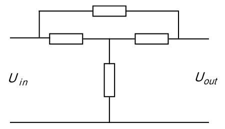
In order to build the filter you can choose from the following components:
2 resistors, 10 kΩ
2 capacitors, 10 nF
2 solenoids, 160 mH (iron-free and with neglible resistance)
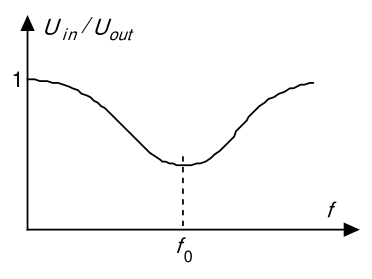
Construct, by combining four of these components, a filter that fulfils the stated conditions. Determine the frequency \(f_0\) and the ratio \(U_{out}/U_{in}\) at this frequency for as many component combinations as possible.
Official English text of the problem.
Answers
- Problem 3. There are 12 valid component placements, interpreting the plotted dip as the magnitude of \(U_{\rm out}/U_{\rm in}\), as specified in the prose.
Define the positions, in order, as \[ (Z_1,Z_2,Z_3,Z_4) = (\text{left horizontal},\text{right horizontal}, \text{upper bridge},\text{vertical shunt}). \] Each \(R\) denotes a \(10\,\mathrm{k\Omega}\) resistor, each \(C\) a \(10\,\mathrm{nF}\) capacitor, and each \(L\) a \(160\,\mathrm{mH}\) solenoid.
| Component placement \((Z_1,Z_2,Z_3,Z_4)\) | \(f_0\) | \(U_{\rm out}/U_{\rm in}\) at \(f_0\) |
|---|---|---|
| \((R,R,C,C)\) or \((C,C,R,R)\) | \(1.59\,\mathrm{kHz}\) | \(2/3 \approx 0.667\) |
| \((R,R,L,L)\) or \((L,L,R,R)\) | \(9.95\,\mathrm{kHz}\) | \(2/3 \approx 0.667\) |
| \((R,L,R,C)\) | \(5.63\,\mathrm{kHz}\) | \(4/29 \approx 0.138\) |
| \((R,C,R,L)\) | \(2.81\,\mathrm{kHz}\) | \(4/29 \approx 0.138\) |
| \((C,R,L,R)\) | \(5.63\,\mathrm{kHz}\) | \(25/29 \approx 0.862\) |
| \((L,R,C,R)\) | \(2.81\,\mathrm{kHz}\) | \(25/29 \approx 0.862\) |
| \((L,C,R,L)\) or \((L,C,C,R)\) | \(5.63\,\mathrm{kHz}\) | \(1/2\) |
| \((C,L,R,C)\) or \((C,L,L,R)\) | \(2.81\,\mathrm{kHz}\) | \(1/2\) |
For every placement, the output and input are in phase at \(f_0\).
Solution
The problem has no numbered subparts. We first derive the response of the given circuit, then identify the component placements and calculate their minima.
Use ideal components with \[ R=1.00\times10^4\,\Omega,\qquad C=1.00\times10^{-8}\,\mathrm F,\qquad L=0.160\,\mathrm H. \] In sinusoidal steady state, using phasors with time dependence \(e^{i\omega t}\), \[ Z_R=R,\qquad Z_L=i\omega L,\qquad Z_C=\frac{1}{i\omega C},\qquad \omega=2\pi f. \] The negligible source impedance fixes the input voltage. The infinite load impedance means that no external current leaves the output terminal.
Let \(V_m\) be the voltage at the junction of \(Z_1,Z_2,Z_4\), measured relative to the common lower conductor. Kirchhoff’s current law gives \[ \frac{V_m-V_{\rm in}}{Z_1} +\frac{V_m-V_{\rm out}}{Z_2} +\frac{V_m}{Z_4}=0, \] \[ \frac{V_{\rm out}-V_m}{Z_2} +\frac{V_{\rm out}-V_{\rm in}}{Z_3}=0. \] Eliminating \(V_m\), the complex voltage ratio is \[ H(\omega)\equiv\frac{V_{\rm out}}{V_{\rm in}} = \frac{Z_1Z_2+Z_4(Z_1+Z_2+Z_3)} {Z_1Z_2+Z_4(Z_1+Z_2+Z_3)+Z_1Z_3}. \] It is convenient to write this as \[ \boxed{H=\frac{K}{K+1}}, \] where \[ \boxed{ K=\frac{Z_2}{Z_3} +\frac{Z_4}{Z_3} +\frac{Z_2Z_4}{Z_1Z_3} +\frac{Z_4}{Z_1}. } \]
Component placements. Define the dimensionless constant \[ \kappa=\frac{L}{R^2C}. \] For each of the following placements, substitution into \(K\) gives \[ K=\alpha+i\left(\beta\omega-\frac{\gamma}{\omega}\right), \qquad \alpha,\beta,\gamma>0. \] The component codes in the table are written in the order \(Z_1Z_2Z_3Z_4\).
| Placement | \(\alpha\) | \(\beta\) | \(\gamma\) |
|---|---|---|---|
| \(RRCC,\ CCRR\) | \(2\) | \(RC\) | \(1/(RC)\) |
| \(RRLL,\ LLRR\) | \(2\) | \(L/R\) | \(R/L\) |
| \(RLRC\) | \(\kappa\) | \(L/R\) | \(2/(RC)\) |
| \(RCRL\) | \(\kappa\) | \(2L/R\) | \(1/(RC)\) |
| \(CRLR\) | \(1/\kappa\) | \(RC\) | \(2R/L\) |
| \(LRCR\) | \(1/\kappa\) | \(2RC\) | \(R/L\) |
| \(LCRL\) | \(1\) | \(L/R\) | \(2/(RC)\) |
| \(LCCR\) | \(1\) | \(RC\) | \(2R/L\) |
| \(CLRC\) | \(1\) | \(2L/R\) | \(1/(RC)\) |
| \(CLLR\) | \(1\) | \(2RC\) | \(R/L\) |
For example, the placement \(RLRC\) means \[ Z_1=R,\quad Z_2=i\omega L,\quad Z_3=R,\quad Z_4=\frac1{i\omega C}. \] It gives \[ K=\frac{i\omega L}{R} +\frac{1}{i\omega CR} +\frac{L}{CR^2} +\frac{1}{i\omega CR} = \kappa+i\left(\frac{\omega L}{R}-\frac{2}{\omega CR}\right), \] as listed.
Frequency dependence and phase. Put \[ u=\beta\omega-\frac{\gamma}{\omega}. \] Then \[ H=\frac{\alpha+iu}{\alpha+1+iu}, \qquad |H|^2=\frac{\alpha^2+u^2}{(\alpha+1)^2+u^2}. \] Since \[ \frac{d|H|^2}{d(u^2)} = \frac{2\alpha+1}{\bigl[(\alpha+1)^2+u^2\bigr]^2}>0, \] the magnitude is smallest when \(u=0\). Moreover, \[ \frac{du}{d\omega}=\beta+\frac{\gamma}{\omega^2}>0, \] so there is exactly one minimum at positive frequency: \[ \boxed{\omega_0=\sqrt{\frac{\gamma}{\beta}}}, \qquad \boxed{f_0=\frac{1}{2\pi}\sqrt{\frac{\gamma}{\beta}}}. \] At this frequency, \[ \boxed{H(\omega_0)=\frac{\alpha}{\alpha+1}>0}. \] Thus the voltage ratio is real and positive: the phase difference is zero, as required.
At both frequency limits, \[ \omega\to0:\quad u\to-\infty, \qquad \omega\to\infty:\quad u\to+\infty, \] and consequently \[ \lim_{\omega\to0}H=\lim_{\omega\to\infty}H=1. \] Every listed placement therefore has the required curve: its magnitude starts at unity, decreases smoothly to a single positive minimum at \(f_0\), and then rises towards unity.
Numerical frequencies and voltage ratios. The table produces four distinct frequencies: \[ f_{RC}=\frac{1}{2\pi RC} =1.5915\times10^3\,\mathrm{Hz} \approx\boxed{1.59\,\mathrm{kHz}}, \] \[ f_{RL}=\frac{R}{2\pi L} =9.9472\times10^3\,\mathrm{Hz} \approx\boxed{9.95\,\mathrm{kHz}}, \] \[ f_+=\frac{1}{2\pi}\sqrt{\frac{2}{LC}} =5.6270\times10^3\,\mathrm{Hz} \approx\boxed{5.63\,\mathrm{kHz}}, \] \[ f_-=\frac{1}{2\pi\sqrt{2LC}} =2.8135\times10^3\,\mathrm{Hz} \approx\boxed{2.81\,\mathrm{kHz}}. \]
Also, \[ \kappa =\frac{0.160}{(10^4)^2(10^{-8})} =0.160=\frac4{25}. \] The possible minimum ratios are therefore \[ \alpha=2:\qquad H_0=\frac23, \] \[ \alpha=\kappa:\qquad H_0=\frac{\kappa}{1+\kappa} =\frac{L}{R^2C+L} =\frac4{29}, \] \[ \alpha=\frac1\kappa:\qquad H_0=\frac{1}{1+\kappa} =\frac{R^2C}{R^2C+L} =\frac{25}{29}, \] \[ \alpha=1:\qquad H_0=\frac12. \] Combining these expressions with the placement table gives all the answers above.
Completeness of the placements. There are 54 assignments of four component types to the four positions, allowing at most two of each type: 18 use two components of each of two types, and 36 use all three types.
The unity limits at both ends require \(K\) to diverge as both \(\omega\to0\) and \(\omega\to\infty\). This gives a simple way to check all assignments. Write each impedance as a positive constant times \(s^p\), with \[ s=i\omega,\qquad p_R=0,\quad p_L=1,\quad p_C=-1. \] The four terms of \(K\) have powers \[ p_2-p_3,\quad p_4-p_3,\quad p_2+p_4-p_1-p_3,\quad p_4-p_1. \] The endpoint condition holds precisely when these powers include both a positive and a negative value. It leaves 22 placements: the 12 already obtained and the following ten.
| Remaining placements | Reason they fail |
|---|---|
| \(RLCC,\ RCLL,\ LRCC,\ CRLL\) | Their only finite positive frequency with real \(H\) is \(\omega=1/\sqrt{LC}\), where \(H=0\). The output phase is then undefined, and the minimum is zero. |
| \(LLRC,\ LLCR,\ CCRL,\ CCLR\) | Their only finite positive frequency with real \(H\) gives \(H=-1\): the phase difference is \(180^\circ\). |
| \(LLCC,\ CCLL\) | They have undamped resonant poles and do not give the illustrated smooth dip. |
For the last two placements, writing \(x=\omega\sqrt{LC}\) explicitly gives \[ H=\frac{(1-x^2)^2}{1-3x^2+x^4}, \] whose denominator vanishes at \[ x^2=\frac{3\pm\sqrt5}{2}. \] Thus the 12 listed placements exhaust the possibilities satisfying the interpreted graph and the zero-phase condition.
The solution was checked against the official solution.
IPhO 1984 · Theorieaufgabe 3
Elektronisches Frequenzfilter
Ein elektronisches Frequenzfilter besteht aus vier Bauelementen, die wie in der oberen Abbildung miteinander verbunden sind. Die Impedanz der Quelle kann vernachlässigt und die Impedanz der Last als unendlich angenommen werden. Das Filter soll so beschaffen sein, dass das Spannungsverhältnis \(U_{out}/U_{in}\) die in der unteren Abbildung dargestellte Frequenzabhängigkeit aufweist, wobei \(U_{in}\) die Eingangsspannung und \(U_{out}\) die Ausgangsspannung ist. Bei der Frequenz \(f_0\) ist die Phasenverschiebung zwischen den beiden Spannungen null.
Zum Aufbau des Filters stehen die folgenden Bauelemente zur Auswahl:
2 Widerstände, 10 kΩ
2 Kondensatoren, 10 nF
2 Spulen, 160 mH (ohne Eisenkern und mit vernachlässigbarem Widerstand)
Konstruieren Sie durch Kombination von vier dieser Bauelemente ein Filter, das die angegebenen Bedingungen erfüllt. Bestimmen Sie für möglichst viele Kombinationen von Bauelementen die Frequenz \(f_0\) und das Verhältnis \(U_{out}/U_{in}\) bei dieser Frequenz.
Aufgabentext aus dem offiziellen englischen Text übersetzt.
Antworten
- Aufgabe 3. Es gibt 12 zulässige Anordnungen der Bauelemente, wenn die dargestellte Absenkung entsprechend der Beschreibung im Text als Betrag von \(U_{\rm out}/U_{\rm in}\) interpretiert wird.
Die Positionen werden in dieser Reihenfolge definiert als \[ (Z_1,Z_2,Z_3,Z_4) = (\text{links waagerecht},\text{rechts waagerecht}, \text{obere Brücke},\text{senkrechter Querzweig}). \] Jedes \(R\) bezeichnet einen Widerstand von \(10\,\mathrm{k\Omega}\), jedes \(C\) einen Kondensator von \(10\,\mathrm{nF}\) und jedes \(L\) eine Spule von \(160\,\mathrm{mH}\).
| Anordnung der Bauelemente \((Z_1,Z_2,Z_3,Z_4)\) | \(f_0\) | \(U_{\rm out}/U_{\rm in}\) bei \(f_0\) |
|---|---|---|
| \((R,R,C,C)\) oder \((C,C,R,R)\) | \(1.59\,\mathrm{kHz}\) | \(2/3 \approx 0.667\) |
| \((R,R,L,L)\) oder \((L,L,R,R)\) | \(9.95\,\mathrm{kHz}\) | \(2/3 \approx 0.667\) |
| \((R,L,R,C)\) | \(5.63\,\mathrm{kHz}\) | \(4/29 \approx 0.138\) |
| \((R,C,R,L)\) | \(2.81\,\mathrm{kHz}\) | \(4/29 \approx 0.138\) |
| \((C,R,L,R)\) | \(5.63\,\mathrm{kHz}\) | \(25/29 \approx 0.862\) |
| \((L,R,C,R)\) | \(2.81\,\mathrm{kHz}\) | \(25/29 \approx 0.862\) |
| \((L,C,R,L)\) oder \((L,C,C,R)\) | \(5.63\,\mathrm{kHz}\) | \(1/2\) |
| \((C,L,R,C)\) oder \((C,L,L,R)\) | \(2.81\,\mathrm{kHz}\) | \(1/2\) |
Bei jeder Anordnung sind Ausgangs- und Eingangsspannung bei \(f_0\) in Phase.
Lösung
Die Aufgabe hat keine nummerierten Teilaufgaben. Wir leiten zunächst das Übertragungsverhalten der gegebenen Schaltung her, ermitteln dann die Anordnungen der Bauelemente und berechnen ihre Minima.
Wir verwenden ideale Bauelemente mit \[ R=1.00\times10^4\,\Omega,\qquad C=1.00\times10^{-8}\,\mathrm F,\qquad L=0.160\,\mathrm H. \] Im eingeschwungenen Zustand bei sinusförmiger Anregung gilt bei Verwendung komplexer Zeiger mit der Zeitabhängigkeit \(e^{i\omega t}\) \[ Z_R=R,\qquad Z_L=i\omega L,\qquad Z_C=\frac{1}{i\omega C},\qquad \omega=2\pi f. \] Die vernachlässigbare Quellenimpedanz legt die Eingangsspannung fest. Die unendliche Lastimpedanz bedeutet, dass kein Strom über einen äußeren Stromkreis aus dem Ausgangsanschluss abfließt.
Es sei \(V_m\) die Spannung am Verbindungspunkt von \(Z_1,Z_2,Z_4\), gemessen gegenüber dem gemeinsamen unteren Leiter. Die Kirchhoffsche Knotenregel liefert \[ \frac{V_m-V_{\rm in}}{Z_1} +\frac{V_m-V_{\rm out}}{Z_2} +\frac{V_m}{Z_4}=0, \] \[ \frac{V_{\rm out}-V_m}{Z_2} +\frac{V_{\rm out}-V_{\rm in}}{Z_3}=0. \] Durch Elimination von \(V_m\) ergibt sich das komplexe Spannungsverhältnis zu \[ H(\omega)\equiv\frac{V_{\rm out}}{V_{\rm in}} = \frac{Z_1Z_2+Z_4(Z_1+Z_2+Z_3)} {Z_1Z_2+Z_4(Z_1+Z_2+Z_3)+Z_1Z_3}. \] Zweckmäßigerweise schreiben wir dies als \[ \boxed{H=\frac{K}{K+1}}, \] wobei \[ \boxed{ K=\frac{Z_2}{Z_3} +\frac{Z_4}{Z_3} +\frac{Z_2Z_4}{Z_1Z_3} +\frac{Z_4}{Z_1}. } \]
Anordnungen der Bauelemente. Wir definieren die dimensionslose Konstante \[ \kappa=\frac{L}{R^2C}. \] Für jede der folgenden Anordnungen ergibt das Einsetzen in \(K\) \[ K=\alpha+i\left(\beta\omega-\frac{\gamma}{\omega}\right), \qquad \alpha,\beta,\gamma>0. \] Die Bauelementcodes in der Tabelle sind in der Reihenfolge \(Z_1Z_2Z_3Z_4\) angegeben.
| Anordnung | \(\alpha\) | \(\beta\) | \(\gamma\) |
|---|---|---|---|
| \(RRCC,\ CCRR\) | \(2\) | \(RC\) | \(1/(RC)\) |
| \(RRLL,\ LLRR\) | \(2\) | \(L/R\) | \(R/L\) |
| \(RLRC\) | \(\kappa\) | \(L/R\) | \(2/(RC)\) |
| \(RCRL\) | \(\kappa\) | \(2L/R\) | \(1/(RC)\) |
| \(CRLR\) | \(1/\kappa\) | \(RC\) | \(2R/L\) |
| \(LRCR\) | \(1/\kappa\) | \(2RC\) | \(R/L\) |
| \(LCRL\) | \(1\) | \(L/R\) | \(2/(RC)\) |
| \(LCCR\) | \(1\) | \(RC\) | \(2R/L\) |
| \(CLRC\) | \(1\) | \(2L/R\) | \(1/(RC)\) |
| \(CLLR\) | \(1\) | \(2RC\) | \(R/L\) |
Beispielsweise bedeutet die Anordnung \(RLRC\) \[ Z_1=R,\quad Z_2=i\omega L,\quad Z_3=R,\quad Z_4=\frac1{i\omega C}. \] Sie ergibt \[ K=\frac{i\omega L}{R} +\frac{1}{i\omega CR} +\frac{L}{CR^2} +\frac{1}{i\omega CR} = \kappa+i\left(\frac{\omega L}{R}-\frac{2}{\omega CR}\right), \] wie in der Tabelle angegeben.
Frequenzabhängigkeit und Phase. Wir setzen \[ u=\beta\omega-\frac{\gamma}{\omega}. \] Dann gilt \[ H=\frac{\alpha+iu}{\alpha+1+iu}, \qquad |H|^2=\frac{\alpha^2+u^2}{(\alpha+1)^2+u^2}. \] Da \[ \frac{d|H|^2}{d(u^2)} = \frac{2\alpha+1}{\bigl[(\alpha+1)^2+u^2\bigr]^2}>0, \] ist der Betrag für \(u=0\) am kleinsten. Außerdem gilt \[ \frac{du}{d\omega}=\beta+\frac{\gamma}{\omega^2}>0, \] sodass es genau ein Minimum bei positiver Frequenz gibt: \[ \boxed{\omega_0=\sqrt{\frac{\gamma}{\beta}}}, \qquad \boxed{f_0=\frac{1}{2\pi}\sqrt{\frac{\gamma}{\beta}}}. \] Bei dieser Frequenz gilt \[ \boxed{H(\omega_0)=\frac{\alpha}{\alpha+1}>0}. \] Das Spannungsverhältnis ist somit reell und positiv: Die Phasendifferenz ist wie gefordert null.
In beiden Frequenzgrenzfällen gilt \[ \omega\to0:\quad u\to-\infty, \qquad \omega\to\infty:\quad u\to+\infty, \] und folglich \[ \lim_{\omega\to0}H=\lim_{\omega\to\infty}H=1. \] Jede aufgeführte Anordnung weist daher den geforderten Kurvenverlauf auf: Ihr Betrag beginnt bei eins, fällt glatt bis zu einem einzigen positiven Minimum bei \(f_0\) ab und steigt anschließend wieder gegen eins an.
Zahlenwerte der Frequenzen und Spannungsverhältnisse. Aus der Tabelle ergeben sich vier verschiedene Frequenzen: \[ f_{RC}=\frac{1}{2\pi RC} =1.5915\times10^3\,\mathrm{Hz} \approx\boxed{1.59\,\mathrm{kHz}}, \] \[ f_{RL}=\frac{R}{2\pi L} =9.9472\times10^3\,\mathrm{Hz} \approx\boxed{9.95\,\mathrm{kHz}}, \] \[ f_+=\frac{1}{2\pi}\sqrt{\frac{2}{LC}} =5.6270\times10^3\,\mathrm{Hz} \approx\boxed{5.63\,\mathrm{kHz}}, \] \[ f_-=\frac{1}{2\pi\sqrt{2LC}} =2.8135\times10^3\,\mathrm{Hz} \approx\boxed{2.81\,\mathrm{kHz}}. \]
Außerdem gilt \[ \kappa =\frac{0.160}{(10^4)^2(10^{-8})} =0.160=\frac4{25}. \] Die möglichen minimalen Spannungsverhältnisse sind daher \[ \alpha=2:\qquad H_0=\frac23, \] \[ \alpha=\kappa:\qquad H_0=\frac{\kappa}{1+\kappa} =\frac{L}{R^2C+L} =\frac4{29}, \] \[ \alpha=\frac1\kappa:\qquad H_0=\frac{1}{1+\kappa} =\frac{R^2C}{R^2C+L} =\frac{25}{29}, \] \[ \alpha=1:\qquad H_0=\frac12. \] Die Kombination dieser Ausdrücke mit der Tabelle der Anordnungen liefert alle oben angegebenen Antworten.
Vollständigkeit der Anordnungen. Es gibt 54 Möglichkeiten, die vier Positionen mit Bauelementtypen zu besetzen, wobei höchstens zwei Bauelemente jedes Typs zulässig sind: 18 verwenden je zwei Bauelemente von zwei Typen, und 36 verwenden alle drei Typen.
Die Grenzwerte eins an beiden Enden erfordern, dass \(K\) sowohl für \(\omega\to0\) als auch für \(\omega\to\infty\) divergiert. Daraus ergibt sich eine einfache Möglichkeit, alle Zuordnungen zu überprüfen. Wir schreiben jede Impedanz als eine positive Konstante mal \(s^p\), mit \[ s=i\omega,\qquad p_R=0,\quad p_L=1,\quad p_C=-1. \] Die vier Terme von \(K\) haben die Exponenten \[ p_2-p_3,\quad p_4-p_3,\quad p_2+p_4-p_1-p_3,\quad p_4-p_1. \] Die Bedingung für die Grenzwerte ist genau dann erfüllt, wenn diese Exponenten sowohl einen positiven als auch einen negativen Wert enthalten. Es bleiben 22 Anordnungen übrig: die 12 bereits ermittelten und die folgenden zehn.
| Verbleibende Anordnungen | Grund für den Ausschluss |
|---|---|
| \(RLCC,\ RCLL,\ LRCC,\ CRLL\) | Ihre einzige endliche positive Frequenz mit reellem \(H\) ist \(\omega=1/\sqrt{LC}\), wobei \(H=0\) gilt. Die Phase der Ausgangsspannung ist dann undefiniert, und das Minimum ist null. |
| \(LLRC,\ LLCR,\ CCRL,\ CCLR\) | Ihre einzige endliche positive Frequenz mit reellem \(H\) ergibt \(H=-1\): Die Phasendifferenz beträgt \(180^\circ\). |
| \(LLCC,\ CCLL\) | Sie haben ungedämpfte Resonanzpole und ergeben nicht die dargestellte glatte Absenkung. |
Für die letzten beiden Anordnungen ergibt sich mit \(x=\omega\sqrt{LC}\) explizit \[ H=\frac{(1-x^2)^2}{1-3x^2+x^4}, \] wobei der Nenner bei \[ x^2=\frac{3\pm\sqrt5}{2} \] verschwindet. Somit erfassen die 12 aufgeführten Anordnungen alle Möglichkeiten, die mit der angegebenen Interpretation des Diagramms vereinbar sind und die Bedingung der Phasendifferenz null erfüllen.
Die Lösung wurde mit der offiziellen Lösung abgeglichen.
IPhO 1984 · Teori sorusu 3
Elektronik frekans filtresi
Bir elektronik frekans filtresi, üstteki şekildeki gibi bağlanmış dört devre elemanından oluşmaktadır. Kaynağın empedansı ihmal edilebilir ve yükün empedansı sonsuz kabul edilebilir. Filtre, \(U_{out}/U_{in}\) gerilim oranının frekansa bağımlılığı alttaki şekilde gösterildiği gibi olacak biçimde tasarlanmalıdır; burada \(U_{in}\) giriş gerilimi, \(U_{out}\) ise çıkış gerilimidir. \(f_0\) frekansında iki gerilim arasındaki faz gecikmesi sıfırdır.
Filtreyi oluşturmak için aşağıdaki devre elemanları arasından seçim yapabilirsiniz:
2 direnç, 10 kΩ
2 kondansatör, 10 nF
2 solenoid, 160 mH (demir çekirdeksiz ve dirençleri ihmal edilebilir)
Bu elemanların dördünü birleştirerek belirtilen koşulları sağlayan bir filtre oluşturunuz. Mümkün olduğunca çok eleman kombinasyonu için \(f_0\) frekansını ve bu frekanstaki \(U_{out}/U_{in}\) oranını belirleyiniz.
Soru metni resmi İngilizce metinden çevrilmiştir.
Cevaplar
- Soru 3. Metinde belirtildiği üzere, grafikteki çukuru \(U_{\rm out}/U_{\rm in}\) oranının büyüklüğü olarak yorumladığımızda 12 geçerli eleman yerleşimi vardır.
Konumları sırasıyla şöyle tanımlayalım: \[ (Z_1,Z_2,Z_3,Z_4) = (\text{sol yatay},\text{sağ yatay}, \text{üst köprü},\text{düşey şönt}). \] Her \(R\), \(10\,\mathrm{k\Omega}\) değerinde bir direnci; her \(C\), \(10\,\mathrm{nF}\) değerinde bir kondansatörü; her \(L\) ise \(160\,\mathrm{mH}\) değerinde bir solenoidi göstermektedir.
| Eleman yerleşimi \((Z_1,Z_2,Z_3,Z_4)\) | \(f_0\) | \(f_0\) frekansında \(U_{\rm out}/U_{\rm in}\) |
|---|---|---|
| \((R,R,C,C)\) veya \((C,C,R,R)\) | \(1.59\,\mathrm{kHz}\) | \(2/3 \approx 0.667\) |
| \((R,R,L,L)\) veya \((L,L,R,R)\) | \(9.95\,\mathrm{kHz}\) | \(2/3 \approx 0.667\) |
| \((R,L,R,C)\) | \(5.63\,\mathrm{kHz}\) | \(4/29 \approx 0.138\) |
| \((R,C,R,L)\) | \(2.81\,\mathrm{kHz}\) | \(4/29 \approx 0.138\) |
| \((C,R,L,R)\) | \(5.63\,\mathrm{kHz}\) | \(25/29 \approx 0.862\) |
| \((L,R,C,R)\) | \(2.81\,\mathrm{kHz}\) | \(25/29 \approx 0.862\) |
| \((L,C,R,L)\) veya \((L,C,C,R)\) | \(5.63\,\mathrm{kHz}\) | \(1/2\) |
| \((C,L,R,C)\) veya \((C,L,L,R)\) | \(2.81\,\mathrm{kHz}\) | \(1/2\) |
Her yerleşimde çıkış ve giriş \(f_0\) frekansında aynı fazdadır.
Çözüm
Sorunun numaralandırılmış alt bölümleri yoktur. Önce verilen devrenin tepkisini türetecek, ardından eleman yerleşimlerini belirleyip bunların minimumlarını hesaplayacağız.
Değerleri \[ R=1.00\times10^4\,\Omega,\qquad C=1.00\times10^{-8}\,\mathrm F,\qquad L=0.160\,\mathrm H \] olan ideal elemanlar kullanalım. Sinüzoidal kararlı durumda, zaman bağımlılığı \(e^{i\omega t}\) olan fazörleri kullanırsak, \[ Z_R=R,\qquad Z_L=i\omega L,\qquad Z_C=\frac{1}{i\omega C},\qquad \omega=2\pi f. \] Kaynak empedansının ihmal edilebilir olması giriş gerilimini sabit tutar. Yük empedansının sonsuz olması, çıkış ucundan dışarıya akım akmadığı anlamına gelir.
\(V_m\), \(Z_1,Z_2,Z_4\) elemanlarının birleştiği düğümün ortak alt iletkene göre ölçülen gerilimi olsun. Kirchhoff'un akım yasası şu denklemleri verir: \[ \frac{V_m-V_{\rm in}}{Z_1} +\frac{V_m-V_{\rm out}}{Z_2} +\frac{V_m}{Z_4}=0, \] \[ \frac{V_{\rm out}-V_m}{Z_2} +\frac{V_{\rm out}-V_{\rm in}}{Z_3}=0. \] \(V_m\) elendiğinde karmaşık gerilim oranı şöyle bulunur: \[ H(\omega)\equiv\frac{V_{\rm out}}{V_{\rm in}} = \frac{Z_1Z_2+Z_4(Z_1+Z_2+Z_3)} {Z_1Z_2+Z_4(Z_1+Z_2+Z_3)+Z_1Z_3}. \] Bu ifadeyi şu biçimde yazmak uygundur: \[ \boxed{H=\frac{K}{K+1}}, \] burada \[ \boxed{ K=\frac{Z_2}{Z_3} +\frac{Z_4}{Z_3} +\frac{Z_2Z_4}{Z_1Z_3} +\frac{Z_4}{Z_1}. } \]
Eleman yerleşimleri. Boyutsuz sabiti şöyle tanımlayalım: \[ \kappa=\frac{L}{R^2C}. \] Aşağıdaki yerleşimlerin her biri için empedanslar \(K\) ifadesinde yerine konulduğunda \[ K=\alpha+i\left(\beta\omega-\frac{\gamma}{\omega}\right), \qquad \alpha,\beta,\gamma>0 \] elde edilir. Tablodaki eleman kodları \(Z_1Z_2Z_3Z_4\) sırasıyla yazılmıştır.
| Yerleşim | \(\alpha\) | \(\beta\) | \(\gamma\) |
|---|---|---|---|
| \(RRCC,\ CCRR\) | \(2\) | \(RC\) | \(1/(RC)\) |
| \(RRLL,\ LLRR\) | \(2\) | \(L/R\) | \(R/L\) |
| \(RLRC\) | \(\kappa\) | \(L/R\) | \(2/(RC)\) |
| \(RCRL\) | \(\kappa\) | \(2L/R\) | \(1/(RC)\) |
| \(CRLR\) | \(1/\kappa\) | \(RC\) | \(2R/L\) |
| \(LRCR\) | \(1/\kappa\) | \(2RC\) | \(R/L\) |
| \(LCRL\) | \(1\) | \(L/R\) | \(2/(RC)\) |
| \(LCCR\) | \(1\) | \(RC\) | \(2R/L\) |
| \(CLRC\) | \(1\) | \(2L/R\) | \(1/(RC)\) |
| \(CLLR\) | \(1\) | \(2RC\) | \(R/L\) |
Örneğin \(RLRC\) yerleşimi şu anlama gelir: \[ Z_1=R,\quad Z_2=i\omega L,\quad Z_3=R,\quad Z_4=\frac1{i\omega C}. \] Bu yerleşim için \[ K=\frac{i\omega L}{R} +\frac{1}{i\omega CR} +\frac{L}{CR^2} +\frac{1}{i\omega CR} = \kappa+i\left(\frac{\omega L}{R}-\frac{2}{\omega CR}\right), \] elde edilir; bu da tabloda verilen ifadedir.
Frekans bağımlılığı ve faz. Şöyle tanımlayalım: \[ u=\beta\omega-\frac{\gamma}{\omega}. \] O hâlde \[ H=\frac{\alpha+iu}{\alpha+1+iu}, \qquad |H|^2=\frac{\alpha^2+u^2}{(\alpha+1)^2+u^2}. \] \[ \frac{d|H|^2}{d(u^2)} = \frac{2\alpha+1}{\bigl[(\alpha+1)^2+u^2\bigr]^2}>0, \] olduğundan büyüklük, \(u=0\) olduğunda en küçüktür. Ayrıca, \[ \frac{du}{d\omega}=\beta+\frac{\gamma}{\omega^2}>0, \] olduğundan pozitif frekanslarda tam olarak bir minimum vardır: \[ \boxed{\omega_0=\sqrt{\frac{\gamma}{\beta}}}, \qquad \boxed{f_0=\frac{1}{2\pi}\sqrt{\frac{\gamma}{\beta}}}. \] Bu frekansta, \[ \boxed{H(\omega_0)=\frac{\alpha}{\alpha+1}>0}. \] Dolayısıyla gerilim oranı reel ve pozitiftir: istendiği gibi faz farkı sıfırdır.
Her iki frekans limitinde, \[ \omega\to0:\quad u\to-\infty, \qquad \omega\to\infty:\quad u\to+\infty, \] ve bunun sonucunda \[ \lim_{\omega\to0}H=\lim_{\omega\to\infty}H=1. \] Bu nedenle listelenen her yerleşim istenen eğriyi verir: büyüklük birden başlar, düzgün biçimde azalarak \(f_0\) frekansında tek bir pozitif minimuma ulaşır ve ardından bire doğru yükselir.
Sayısal frekanslar ve gerilim oranları. Tablodan dört farklı frekans elde edilir: \[ f_{RC}=\frac{1}{2\pi RC} =1.5915\times10^3\,\mathrm{Hz} \approx\boxed{1.59\,\mathrm{kHz}}, \] \[ f_{RL}=\frac{R}{2\pi L} =9.9472\times10^3\,\mathrm{Hz} \approx\boxed{9.95\,\mathrm{kHz}}, \] \[ f_+=\frac{1}{2\pi}\sqrt{\frac{2}{LC}} =5.6270\times10^3\,\mathrm{Hz} \approx\boxed{5.63\,\mathrm{kHz}}, \] \[ f_-=\frac{1}{2\pi\sqrt{2LC}} =2.8135\times10^3\,\mathrm{Hz} \approx\boxed{2.81\,\mathrm{kHz}}. \]
Ayrıca, \[ \kappa =\frac{0.160}{(10^4)^2(10^{-8})} =0.160=\frac4{25}. \] Dolayısıyla olası minimum oranlar şunlardır: \[ \alpha=2:\qquad H_0=\frac23, \] \[ \alpha=\kappa:\qquad H_0=\frac{\kappa}{1+\kappa} =\frac{L}{R^2C+L} =\frac4{29}, \] \[ \alpha=\frac1\kappa:\qquad H_0=\frac{1}{1+\kappa} =\frac{R^2C}{R^2C+L} =\frac{25}{29}, \] \[ \alpha=1:\qquad H_0=\frac12. \] Bu ifadeler yerleşim tablosuyla birleştirildiğinde yukarıdaki cevapların tümü elde edilir.
Yerleşimlerin eksiksizliği. Her türden en fazla iki eleman kullanılmasına izin verildiğinde, dört konuma eleman türlerini atamanın 54 yolu vardır: bunların 18'inde iki türün her birinden ikişer eleman, 36'sında ise üç türün tümü kullanılır.
Her iki uçtaki limitin bir olması, \(K\)'nın hem \(\omega\to0\) hem de \(\omega\to\infty\) iken ıraksamasını gerektirir. Bu, tüm atamaları kontrol etmek için basit bir yol sunar. Her empedansı pozitif bir sabit ile \(s^p\)'nin çarpımı olarak yazalım; burada \[ s=i\omega,\qquad p_R=0,\quad p_L=1,\quad p_C=-1. \] \(K\)'nın dört teriminin üsleri şunlardır: \[ p_2-p_3,\quad p_4-p_3,\quad p_2+p_4-p_1-p_3,\quad p_4-p_1. \] Uç nokta koşulu, ancak ve ancak bu üsler arasında hem pozitif hem de negatif bir değer bulunduğunda sağlanır. Bu koşulu sağlayan 22 yerleşim kalır: daha önce elde edilen 12 yerleşim ve aşağıdaki on yerleşim.
| Kalan yerleşimler | Koşulları sağlamama nedenleri |
|---|---|
| \(RLCC,\ RCLL,\ LRCC,\ CRLL\) | \(H\)'nin reel olduğu tek sonlu pozitif frekans \(\omega=1/\sqrt{LC}\)'dir ve burada \(H=0\) olur. Bu durumda çıkışın fazı tanımsızdır ve minimum sıfırdır. |
| \(LLRC,\ LLCR,\ CCRL,\ CCLR\) | \(H\)'nin reel olduğu tek sonlu pozitif frekansta \(H=-1\) olur: faz farkı \(180^\circ\)'dir. |
| \(LLCC,\ CCLL\) | Sönümsüz rezonans kutuplarına sahiptirler ve şekilde gösterilen düzgün çukuru vermezler. |
Son iki yerleşim için \(x=\omega\sqrt{LC}\) yazıldığında açıkça \[ H=\frac{(1-x^2)^2}{1-3x^2+x^4}, \] elde edilir; bu ifadenin paydası \[ x^2=\frac{3\pm\sqrt5}{2} \] değerlerinde sıfır olur. Dolayısıyla listelenen 12 yerleşim, grafiğin belirtilen yorumunu ve sıfır faz farkı koşulunu sağlayan tüm olasılıkları kapsar.
Çözüm, resmi çözümle karşılaştırılarak kontrol edildi.
IPhO 1984 · Problema teórico 3
Filtro electrónico de frecuencias
Un filtro electrónico de frecuencias consta de cuatro componentes conectados como se muestra en la figura superior. La impedancia de la fuente puede despreciarse y la impedancia de la carga puede considerarse infinita. El filtro debe ser tal que la relación de tensiones \(U_{out}/U_{in}\) tenga la dependencia con la frecuencia mostrada en la figura inferior, donde \(U_{in}\) es la tensión de entrada y \(U_{out}\) es la tensión de salida. A la frecuencia \(f_0\), el desfase entre las dos tensiones es cero.
Para construir el filtro, se puede elegir entre los siguientes componentes:
2 resistencias, 10 kΩ
2 condensadores, 10 nF
2 solenoides, 160 mH (sin núcleo de hierro y con resistencia despreciable)
Construya, combinando cuatro de estos componentes, un filtro que cumpla las condiciones indicadas. Determine la frecuencia \(f_0\) y la relación \(U_{out}/U_{in}\) a esta frecuencia para tantas combinaciones de componentes como sea posible.
Enunciado traducido del texto oficial en inglés.
Respuestas
- Problema 3. Hay 12 disposiciones válidas de los componentes, interpretando el mínimo de la gráfica como el módulo de \(U_{\rm out}/U_{\rm in}\), tal como se especifica en el texto.
Definimos las posiciones, en orden, como \[ (Z_1,Z_2,Z_3,Z_4) = (\text{horizontal izquierda},\text{horizontal derecha}, \text{puente superior},\text{derivación vertical}). \] Cada \(R\) representa una resistencia de \(10\,\mathrm{k\Omega}\), cada \(C\) un condensador de \(10\,\mathrm{nF}\) y cada \(L\) un solenoide de \(160\,\mathrm{mH}\).
| Disposición de los componentes \((Z_1,Z_2,Z_3,Z_4)\) | \(f_0\) | \(U_{\rm out}/U_{\rm in}\) a \(f_0\) |
|---|---|---|
| \((R,R,C,C)\) o \((C,C,R,R)\) | \(1.59\,\mathrm{kHz}\) | \(2/3 \approx 0.667\) |
| \((R,R,L,L)\) o \((L,L,R,R)\) | \(9.95\,\mathrm{kHz}\) | \(2/3 \approx 0.667\) |
| \((R,L,R,C)\) | \(5.63\,\mathrm{kHz}\) | \(4/29 \approx 0.138\) |
| \((R,C,R,L)\) | \(2.81\,\mathrm{kHz}\) | \(4/29 \approx 0.138\) |
| \((C,R,L,R)\) | \(5.63\,\mathrm{kHz}\) | \(25/29 \approx 0.862\) |
| \((L,R,C,R)\) | \(2.81\,\mathrm{kHz}\) | \(25/29 \approx 0.862\) |
| \((L,C,R,L)\) o \((L,C,C,R)\) | \(5.63\,\mathrm{kHz}\) | \(1/2\) |
| \((C,L,R,C)\) o \((C,L,L,R)\) | \(2.81\,\mathrm{kHz}\) | \(1/2\) |
En todas las disposiciones, la salida y la entrada están en fase a \(f_0\).
Solución
El problema no tiene apartados numerados. Primero deducimos la respuesta del circuito dado; después identificamos las disposiciones de los componentes y calculamos sus mínimos.
Utilizamos componentes ideales con \[ R=1.00\times10^4\,\Omega,\qquad C=1.00\times10^{-8}\,\mathrm F,\qquad L=0.160\,\mathrm H. \] En régimen sinusoidal estacionario, utilizando fasores con dependencia temporal \(e^{i\omega t}\), \[ Z_R=R,\qquad Z_L=i\omega L,\qquad Z_C=\frac{1}{i\omega C},\qquad \omega=2\pi f. \] La impedancia despreciable de la fuente fija la tensión de entrada. La impedancia infinita de la carga significa que no sale corriente hacia el exterior por el terminal de salida.
Sea \(V_m\) la tensión en el punto de unión de \(Z_1,Z_2,Z_4\), medida respecto al conductor inferior común. La ley de corrientes de Kirchhoff da \[ \frac{V_m-V_{\rm in}}{Z_1} +\frac{V_m-V_{\rm out}}{Z_2} +\frac{V_m}{Z_4}=0, \] \[ \frac{V_{\rm out}-V_m}{Z_2} +\frac{V_{\rm out}-V_{\rm in}}{Z_3}=0. \] Eliminando \(V_m\), la relación compleja de tensiones es \[ H(\omega)\equiv\frac{V_{\rm out}}{V_{\rm in}} = \frac{Z_1Z_2+Z_4(Z_1+Z_2+Z_3)} {Z_1Z_2+Z_4(Z_1+Z_2+Z_3)+Z_1Z_3}. \] Resulta conveniente escribirla como \[ \boxed{H=\frac{K}{K+1}}, \] donde \[ \boxed{ K=\frac{Z_2}{Z_3} +\frac{Z_4}{Z_3} +\frac{Z_2Z_4}{Z_1Z_3} +\frac{Z_4}{Z_1}. } \]
Disposiciones de los componentes. Definimos la constante adimensional \[ \kappa=\frac{L}{R^2C}. \] Para cada una de las siguientes disposiciones, la sustitución en \(K\) da \[ K=\alpha+i\left(\beta\omega-\frac{\gamma}{\omega}\right), \qquad \alpha,\beta,\gamma>0. \] Los códigos de los componentes en la tabla están escritos en el orden \(Z_1Z_2Z_3Z_4\).
| Disposición | \(\alpha\) | \(\beta\) | \(\gamma\) |
|---|---|---|---|
| \(RRCC,\ CCRR\) | \(2\) | \(RC\) | \(1/(RC)\) |
| \(RRLL,\ LLRR\) | \(2\) | \(L/R\) | \(R/L\) |
| \(RLRC\) | \(\kappa\) | \(L/R\) | \(2/(RC)\) |
| \(RCRL\) | \(\kappa\) | \(2L/R\) | \(1/(RC)\) |
| \(CRLR\) | \(1/\kappa\) | \(RC\) | \(2R/L\) |
| \(LRCR\) | \(1/\kappa\) | \(2RC\) | \(R/L\) |
| \(LCRL\) | \(1\) | \(L/R\) | \(2/(RC)\) |
| \(LCCR\) | \(1\) | \(RC\) | \(2R/L\) |
| \(CLRC\) | \(1\) | \(2L/R\) | \(1/(RC)\) |
| \(CLLR\) | \(1\) | \(2RC\) | \(R/L\) |
Por ejemplo, la disposición \(RLRC\) significa \[ Z_1=R,\quad Z_2=i\omega L,\quad Z_3=R,\quad Z_4=\frac1{i\omega C}. \] Esta da \[ K=\frac{i\omega L}{R} +\frac{1}{i\omega CR} +\frac{L}{CR^2} +\frac{1}{i\omega CR} = \kappa+i\left(\frac{\omega L}{R}-\frac{2}{\omega CR}\right), \] como se indica en la tabla.
Dependencia con la frecuencia y fase. Sea \[ u=\beta\omega-\frac{\gamma}{\omega}. \] Entonces \[ H=\frac{\alpha+iu}{\alpha+1+iu}, \qquad |H|^2=\frac{\alpha^2+u^2}{(\alpha+1)^2+u^2}. \] Puesto que \[ \frac{d|H|^2}{d(u^2)} = \frac{2\alpha+1}{\bigl[(\alpha+1)^2+u^2\bigr]^2}>0, \] el módulo es mínimo cuando \(u=0\). Además, \[ \frac{du}{d\omega}=\beta+\frac{\gamma}{\omega^2}>0, \] por lo que existe exactamente un mínimo a una frecuencia positiva: \[ \boxed{\omega_0=\sqrt{\frac{\gamma}{\beta}}}, \qquad \boxed{f_0=\frac{1}{2\pi}\sqrt{\frac{\gamma}{\beta}}}. \] A esta frecuencia, \[ \boxed{H(\omega_0)=\frac{\alpha}{\alpha+1}>0}. \] Por tanto, la relación de tensiones es real y positiva: la diferencia de fase es cero, como se requiere.
En ambos límites de frecuencia, \[ \omega\to0:\quad u\to-\infty, \qquad \omega\to\infty:\quad u\to+\infty, \] y, en consecuencia, \[ \lim_{\omega\to0}H=\lim_{\omega\to\infty}H=1. \] Por tanto, todas las disposiciones enumeradas presentan la curva requerida: su módulo parte de la unidad, disminuye suavemente hasta un único mínimo positivo a \(f_0\) y luego aumenta hacia la unidad.
Valores numéricos de las frecuencias y las relaciones de tensiones. La tabla da cuatro frecuencias distintas: \[ f_{RC}=\frac{1}{2\pi RC} =1.5915\times10^3\,\mathrm{Hz} \approx\boxed{1.59\,\mathrm{kHz}}, \] \[ f_{RL}=\frac{R}{2\pi L} =9.9472\times10^3\,\mathrm{Hz} \approx\boxed{9.95\,\mathrm{kHz}}, \] \[ f_+=\frac{1}{2\pi}\sqrt{\frac{2}{LC}} =5.6270\times10^3\,\mathrm{Hz} \approx\boxed{5.63\,\mathrm{kHz}}, \] \[ f_-=\frac{1}{2\pi\sqrt{2LC}} =2.8135\times10^3\,\mathrm{Hz} \approx\boxed{2.81\,\mathrm{kHz}}. \]
Además, \[ \kappa =\frac{0.160}{(10^4)^2(10^{-8})} =0.160=\frac4{25}. \] Por tanto, los posibles valores mínimos de la relación son \[ \alpha=2:\qquad H_0=\frac23, \] \[ \alpha=\kappa:\qquad H_0=\frac{\kappa}{1+\kappa} =\frac{L}{R^2C+L} =\frac4{29}, \] \[ \alpha=\frac1\kappa:\qquad H_0=\frac{1}{1+\kappa} =\frac{R^2C}{R^2C+L} =\frac{25}{29}, \] \[ \alpha=1:\qquad H_0=\frac12. \] Combinando estas expresiones con la tabla de disposiciones se obtienen todas las respuestas anteriores.
Exhaustividad de las disposiciones. Hay 54 asignaciones de tipos de componentes a las cuatro posiciones, permitiendo como máximo dos de cada tipo: 18 utilizan dos componentes de cada uno de dos tipos, y 36 utilizan los tres tipos.
Los límites iguales a la unidad en ambos extremos requieren que \(K\) diverja tanto cuando \(\omega\to0\) como cuando \(\omega\to\infty\). Esto proporciona una forma sencilla de comprobar todas las asignaciones. Escribimos cada impedancia como una constante positiva multiplicada por \(s^p\), con \[ s=i\omega,\qquad p_R=0,\quad p_L=1,\quad p_C=-1. \] Los cuatro términos de \(K\) tienen los exponentes \[ p_2-p_3,\quad p_4-p_3,\quad p_2+p_4-p_1-p_3,\quad p_4-p_1. \] La condición en los extremos se cumple precisamente cuando estos exponentes incluyen tanto un valor positivo como uno negativo. Quedan así 22 disposiciones: las 12 ya obtenidas y las diez siguientes.
| Disposiciones restantes | Motivo por el que no cumplen las condiciones |
|---|---|
| \(RLCC,\ RCLL,\ LRCC,\ CRLL\) | Su única frecuencia positiva finita con \(H\) real es \(\omega=1/\sqrt{LC}\), donde \(H=0\). La fase de salida queda entonces indefinida y el mínimo es cero. |
| \(LLRC,\ LLCR,\ CCRL,\ CCLR\) | Su única frecuencia positiva finita con \(H\) real da \(H=-1\): la diferencia de fase es de \(180^\circ\). |
| \(LLCC,\ CCLL\) | Tienen polos resonantes no amortiguados y no producen el mínimo suave ilustrado. |
Para las dos últimas disposiciones, al escribir \(x=\omega\sqrt{LC}\) se obtiene explícitamente \[ H=\frac{(1-x^2)^2}{1-3x^2+x^4}, \] cuyo denominador se anula en \[ x^2=\frac{3\pm\sqrt5}{2}. \] Por tanto, las 12 disposiciones enumeradas agotan las posibilidades que satisfacen la interpretación de la gráfica y la condición de desfase nulo.
La solución se comprobó con la solución oficial.
IPhO 1984 · 理论题 3
电子频率滤波器
一个电子频率滤波器由四个元件按上图所示方式连接而成。信号源的阻抗可以忽略,负载的阻抗可视为无穷大。滤波器应使电压比 \(U_{out}/U_{in}\) 随频率的变化关系如下图所示,其中 \(U_{in}\) 为输入电压,\(U_{out}\) 为输出电压。在频率 \(f_0\) 处,两个电压之间的相位滞后为零。
为搭建该滤波器,你可以从以下元件中进行选择:
2 个电阻,10 kΩ
2 个电容,10 nF
2 个螺线管,160 mH(无铁芯,且电阻可忽略)
将其中四个元件组合起来,构成满足上述条件的滤波器。尽可能多地找出可行的元件组合,并确定各组合的频率 \(f_0\) 及该频率下的电压比 \(U_{out}/U_{in}\)。
题目译自官方英文原文。
答案
- 题目 3。 按照文字说明,将图中的凹谷理解为 \(U_{\rm out}/U_{\rm in}\) 的模随频率的变化,共有 12 种有效的元件配置。
按顺序定义各位置为 \[ (Z_1,Z_2,Z_3,Z_4) = (\text{左侧水平支路},\text{右侧水平支路}, \text{上方跨接支路},\text{竖直分流支路}). \] 每个 \(R\) 表示一个 \(10\,\mathrm{k\Omega}\) 的电阻,每个 \(C\) 表示一个 \(10\,\mathrm{nF}\) 的电容,每个 \(L\) 表示一个 \(160\,\mathrm{mH}\) 的螺线管。
| 元件配置 \((Z_1,Z_2,Z_3,Z_4)\) | \(f_0\) | \(f_0\) 处的 \(U_{\rm out}/U_{\rm in}\) |
|---|---|---|
| \((R,R,C,C)\) 或 \((C,C,R,R)\) | \(1.59\,\mathrm{kHz}\) | \(2/3 \approx 0.667\) |
| \((R,R,L,L)\) 或 \((L,L,R,R)\) | \(9.95\,\mathrm{kHz}\) | \(2/3 \approx 0.667\) |
| \((R,L,R,C)\) | \(5.63\,\mathrm{kHz}\) | \(4/29 \approx 0.138\) |
| \((R,C,R,L)\) | \(2.81\,\mathrm{kHz}\) | \(4/29 \approx 0.138\) |
| \((C,R,L,R)\) | \(5.63\,\mathrm{kHz}\) | \(25/29 \approx 0.862\) |
| \((L,R,C,R)\) | \(2.81\,\mathrm{kHz}\) | \(25/29 \approx 0.862\) |
| \((L,C,R,L)\) 或 \((L,C,C,R)\) | \(5.63\,\mathrm{kHz}\) | \(1/2\) |
| \((C,L,R,C)\) 或 \((C,L,L,R)\) | \(2.81\,\mathrm{kHz}\) | \(1/2\) |
对于每一种配置,输出电压与输入电压都在 \(f_0\) 处同相。
解答
本题没有编号的小问。我们先推导给定电路的响应,再找出元件配置并计算其最小值。
采用理想元件,其参数为 \[ R=1.00\times10^4\,\Omega,\qquad C=1.00\times10^{-8}\,\mathrm F,\qquad L=0.160\,\mathrm H. \] 在正弦稳态下,采用时间依赖关系为 \(e^{i\omega t}\) 的相量表示, \[ Z_R=R,\qquad Z_L=i\omega L,\qquad Z_C=\frac{1}{i\omega C},\qquad \omega=2\pi f. \] 信号源阻抗可忽略,因此输入电压固定。负载阻抗为无穷大,意味着没有电流从输出端流向外部负载。
设 \(V_m\) 为 \(Z_1,Z_2,Z_4\) 连接点相对于下方公共导线的电压。由基尔霍夫电流定律得 \[ \frac{V_m-V_{\rm in}}{Z_1} +\frac{V_m-V_{\rm out}}{Z_2} +\frac{V_m}{Z_4}=0, \] \[ \frac{V_{\rm out}-V_m}{Z_2} +\frac{V_{\rm out}-V_{\rm in}}{Z_3}=0. \] 消去 \(V_m\),得到复电压比 \[ H(\omega)\equiv\frac{V_{\rm out}}{V_{\rm in}} = \frac{Z_1Z_2+Z_4(Z_1+Z_2+Z_3)} {Z_1Z_2+Z_4(Z_1+Z_2+Z_3)+Z_1Z_3}. \] 为方便起见,将其写成 \[ \boxed{H=\frac{K}{K+1}}, \] 其中 \[ \boxed{ K=\frac{Z_2}{Z_3} +\frac{Z_4}{Z_3} +\frac{Z_2Z_4}{Z_1Z_3} +\frac{Z_4}{Z_1}. } \]
元件配置。 定义无量纲常数 \[ \kappa=\frac{L}{R^2C}. \] 对于以下每一种配置,代入 \(K\) 可得 \[ K=\alpha+i\left(\beta\omega-\frac{\gamma}{\omega}\right), \qquad \alpha,\beta,\gamma>0. \] 表中的元件代号按 \(Z_1Z_2Z_3Z_4\) 的顺序排列。
| 配置 | \(\alpha\) | \(\beta\) | \(\gamma\) |
|---|---|---|---|
| \(RRCC,\ CCRR\) | \(2\) | \(RC\) | \(1/(RC)\) |
| \(RRLL,\ LLRR\) | \(2\) | \(L/R\) | \(R/L\) |
| \(RLRC\) | \(\kappa\) | \(L/R\) | \(2/(RC)\) |
| \(RCRL\) | \(\kappa\) | \(2L/R\) | \(1/(RC)\) |
| \(CRLR\) | \(1/\kappa\) | \(RC\) | \(2R/L\) |
| \(LRCR\) | \(1/\kappa\) | \(2RC\) | \(R/L\) |
| \(LCRL\) | \(1\) | \(L/R\) | \(2/(RC)\) |
| \(LCCR\) | \(1\) | \(RC\) | \(2R/L\) |
| \(CLRC\) | \(1\) | \(2L/R\) | \(1/(RC)\) |
| \(CLLR\) | \(1\) | \(2RC\) | \(R/L\) |
例如,配置 \(RLRC\) 表示 \[ Z_1=R,\quad Z_2=i\omega L,\quad Z_3=R,\quad Z_4=\frac1{i\omega C}. \] 由此得到 \[ K=\frac{i\omega L}{R} +\frac{1}{i\omega CR} +\frac{L}{CR^2} +\frac{1}{i\omega CR} = \kappa+i\left(\frac{\omega L}{R}-\frac{2}{\omega CR}\right), \] 与表中所列结果一致。
频率依赖关系与相位。 令 \[ u=\beta\omega-\frac{\gamma}{\omega}. \] 则 \[ H=\frac{\alpha+iu}{\alpha+1+iu}, \qquad |H|^2=\frac{\alpha^2+u^2}{(\alpha+1)^2+u^2}. \] 由于 \[ \frac{d|H|^2}{d(u^2)} = \frac{2\alpha+1}{\bigl[(\alpha+1)^2+u^2\bigr]^2}>0, \] 故当 \(u=0\) 时,模最小。此外, \[ \frac{du}{d\omega}=\beta+\frac{\gamma}{\omega^2}>0, \] 因此在正频率范围内恰有一个最小值,其位置为 \[ \boxed{\omega_0=\sqrt{\frac{\gamma}{\beta}}}, \qquad \boxed{f_0=\frac{1}{2\pi}\sqrt{\frac{\gamma}{\beta}}}. \] 在此频率下, \[ \boxed{H(\omega_0)=\frac{\alpha}{\alpha+1}>0}. \] 因此,电压比为正实数,即相位差为零,满足题目要求。
在频率的两个极限下, \[ \omega\to0:\quad u\to-\infty, \qquad \omega\to\infty:\quad u\to+\infty, \] 从而 \[ \lim_{\omega\to0}H=\lim_{\omega\to\infty}H=1. \] 因此,所列的每一种配置都具有所要求的曲线:其模从 1 开始,平滑下降,在 \(f_0\) 处达到唯一的正最小值,然后上升并趋近于 1。
频率与电压比的数值。 由表可得四个不同的频率: \[ f_{RC}=\frac{1}{2\pi RC} =1.5915\times10^3\,\mathrm{Hz} \approx\boxed{1.59\,\mathrm{kHz}}, \] \[ f_{RL}=\frac{R}{2\pi L} =9.9472\times10^3\,\mathrm{Hz} \approx\boxed{9.95\,\mathrm{kHz}}, \] \[ f_+=\frac{1}{2\pi}\sqrt{\frac{2}{LC}} =5.6270\times10^3\,\mathrm{Hz} \approx\boxed{5.63\,\mathrm{kHz}}, \] \[ f_-=\frac{1}{2\pi\sqrt{2LC}} =2.8135\times10^3\,\mathrm{Hz} \approx\boxed{2.81\,\mathrm{kHz}}. \]
另外, \[ \kappa =\frac{0.160}{(10^4)^2(10^{-8})} =0.160=\frac4{25}. \] 因此,可能的最小电压比为 \[ \alpha=2:\qquad H_0=\frac23, \] \[ \alpha=\kappa:\qquad H_0=\frac{\kappa}{1+\kappa} =\frac{L}{R^2C+L} =\frac4{29}, \] \[ \alpha=\frac1\kappa:\qquad H_0=\frac{1}{1+\kappa} =\frac{R^2C}{R^2C+L} =\frac{25}{29}, \] \[ \alpha=1:\qquad H_0=\frac12. \] 将这些表达式与配置表结合,即可得到上述全部答案。
配置的完备性。 将四个元件按类型分配到四个位置,且每种类型至多使用两个,共有 54 种配置:其中 18 种使用两种类型的元件,每种各两个;36 种使用全部三种类型的元件。
两端的极限均为 1,要求 \(K\) 在 \(\omega\to0\) 和 \(\omega\to\infty\) 时都发散。这提供了一种检查所有配置的简便方法。将每个阻抗写成一个正常数与 \(s^p\) 的乘积,其中 \[ s=i\omega,\qquad p_R=0,\quad p_L=1,\quad p_C=-1. \] \(K\) 的四项所对应的幂指数为 \[ p_2-p_3,\quad p_4-p_3,\quad p_2+p_4-p_1-p_3,\quad p_4-p_1. \] 当且仅当这些幂指数中既有正值又有负值时,端点条件成立。由此筛选出 22 种配置:已得到的 12 种,以及以下十种。
| 其余配置 | 不满足要求的原因 |
|---|---|
| \(RLCC,\ RCLL,\ LRCC,\ CRLL\) | 使 \(H\) 为实数的唯一有限正频率为 \(\omega=1/\sqrt{LC}\),此时 \(H=0\)。此时输出相位无定义,且最小值为零。 |
| \(LLRC,\ LLCR,\ CCRL,\ CCLR\) | 在使 \(H\) 为实数的唯一有限正频率处,\(H=-1\):相位差为 \(180^\circ\)。 |
| \(LLCC,\ CCLL\) | 它们具有无阻尼谐振极点,不能产生图示的平滑凹谷。 |
对于最后两种配置,令 \(x=\omega\sqrt{LC}\),可显式写出 \[ H=\frac{(1-x^2)^2}{1-3x^2+x^4}, \] 其分母在以下位置为零: \[ x^2=\frac{3\pm\sqrt5}{2}. \] 因此,所列的 12 种配置已穷尽所有满足上述图像解释和零相位差条件的可能情况。
解答已与官方解答核对。
IPhO 1984 · Теоретическая задача 3
Электронный частотный фильтр
Электронный частотный фильтр состоит из четырёх элементов, соединённых так, как показано на верхнем рисунке. Импедансом источника можно пренебречь, а импеданс нагрузки можно считать бесконечным. Фильтр должен обеспечивать зависимость отношения напряжений \(U_{out}/U_{in}\) от частоты, показанную на нижнем рисунке, где \(U_{in}\) — входное напряжение, а \(U_{out}\) — выходное напряжение. При частоте \(f_0\) сдвиг фаз между этими двумя напряжениями равен нулю.
Для построения фильтра можно выбрать элементы из следующего набора:
2 резистора по 10 кОм
2 конденсатора по 10 нФ
2 катушки индуктивности по 160 мГн (без железного сердечника и с пренебрежимо малым сопротивлением)
Соберите из четырёх этих элементов фильтр, удовлетворяющий указанным условиям. Определите частоту \(f_0\) и отношение \(U_{out}/U_{in}\) при этой частоте для как можно большего числа комбинаций элементов.
Условие переведено с официального английского текста.
Ответы
- Задача 3. Существует 12 допустимых вариантов расположения элементов, если показанную на графике кривую с провалом понимать как зависимость модуля \(U_{\rm out}/U_{\rm in}\), как указано в тексте.
Обозначим позиции элементов в следующем порядке: \[ (Z_1,Z_2,Z_3,Z_4) = (\text{левая горизонтальная},\text{правая горизонтальная}, \text{верхняя перемычка},\text{вертикальный шунт}). \] Каждая буква \(R\) обозначает резистор сопротивлением \(10\,\mathrm{k\Omega}\), каждая \(C\) — конденсатор ёмкостью \(10\,\mathrm{nF}\), а каждая \(L\) — катушку индуктивностью \(160\,\mathrm{mH}\).
| Расположение элементов \((Z_1,Z_2,Z_3,Z_4)\) | \(f_0\) | \(U_{\rm out}/U_{\rm in}\) при \(f_0\) |
|---|---|---|
| \((R,R,C,C)\) или \((C,C,R,R)\) | \(1.59\,\mathrm{kHz}\) | \(2/3 \approx 0.667\) |
| \((R,R,L,L)\) или \((L,L,R,R)\) | \(9.95\,\mathrm{kHz}\) | \(2/3 \approx 0.667\) |
| \((R,L,R,C)\) | \(5.63\,\mathrm{kHz}\) | \(4/29 \approx 0.138\) |
| \((R,C,R,L)\) | \(2.81\,\mathrm{kHz}\) | \(4/29 \approx 0.138\) |
| \((C,R,L,R)\) | \(5.63\,\mathrm{kHz}\) | \(25/29 \approx 0.862\) |
| \((L,R,C,R)\) | \(2.81\,\mathrm{kHz}\) | \(25/29 \approx 0.862\) |
| \((L,C,R,L)\) или \((L,C,C,R)\) | \(5.63\,\mathrm{kHz}\) | \(1/2\) |
| \((C,L,R,C)\) или \((C,L,L,R)\) | \(2.81\,\mathrm{kHz}\) | \(1/2\) |
Для каждого варианта расположения элементов выходное и входное напряжения совпадают по фазе при \(f_0\).
Решение
В задаче нет пронумерованных подпунктов. Сначала выведем передаточную функцию данной схемы, затем найдём подходящие варианты расположения элементов и вычислим соответствующие минимумы.
Будем считать элементы идеальными, причём \[ R=1.00\times10^4\,\Omega,\qquad C=1.00\times10^{-8}\,\mathrm F,\qquad L=0.160\,\mathrm H. \] В установившемся синусоидальном режиме, используя комплексные амплитуды с временной зависимостью \(e^{i\omega t}\), получаем \[ Z_R=R,\qquad Z_L=i\omega L,\qquad Z_C=\frac{1}{i\omega C},\qquad \omega=2\pi f. \] Пренебрежимо малый импеданс источника означает, что входное напряжение задано. Бесконечный импеданс нагрузки означает, что из выходного вывода во внешнюю цепь ток не течёт.
Пусть \(V_m\) — напряжение в узле соединения \(Z_1,Z_2,Z_4\), отсчитываемое относительно общего нижнего проводника. По первому закону Кирхгофа \[ \frac{V_m-V_{\rm in}}{Z_1} +\frac{V_m-V_{\rm out}}{Z_2} +\frac{V_m}{Z_4}=0, \] \[ \frac{V_{\rm out}-V_m}{Z_2} +\frac{V_{\rm out}-V_{\rm in}}{Z_3}=0. \] Исключая \(V_m\), получаем комплексное отношение напряжений: \[ H(\omega)\equiv\frac{V_{\rm out}}{V_{\rm in}} = \frac{Z_1Z_2+Z_4(Z_1+Z_2+Z_3)} {Z_1Z_2+Z_4(Z_1+Z_2+Z_3)+Z_1Z_3}. \] Его удобно записать в виде \[ \boxed{H=\frac{K}{K+1}}, \] где \[ \boxed{ K=\frac{Z_2}{Z_3} +\frac{Z_4}{Z_3} +\frac{Z_2Z_4}{Z_1Z_3} +\frac{Z_4}{Z_1}. } \]
Расположение элементов. Введём безразмерную постоянную \[ \kappa=\frac{L}{R^2C}. \] Для каждого из следующих вариантов расположения элементов подстановка в выражение для \(K\) даёт \[ K=\alpha+i\left(\beta\omega-\frac{\gamma}{\omega}\right), \qquad \alpha,\beta,\gamma>0. \] Буквенные обозначения элементов в таблице записаны в порядке \(Z_1Z_2Z_3Z_4\).
| Расположение | \(\alpha\) | \(\beta\) | \(\gamma\) |
|---|---|---|---|
| \(RRCC,\ CCRR\) | \(2\) | \(RC\) | \(1/(RC)\) |
| \(RRLL,\ LLRR\) | \(2\) | \(L/R\) | \(R/L\) |
| \(RLRC\) | \(\kappa\) | \(L/R\) | \(2/(RC)\) |
| \(RCRL\) | \(\kappa\) | \(2L/R\) | \(1/(RC)\) |
| \(CRLR\) | \(1/\kappa\) | \(RC\) | \(2R/L\) |
| \(LRCR\) | \(1/\kappa\) | \(2RC\) | \(R/L\) |
| \(LCRL\) | \(1\) | \(L/R\) | \(2/(RC)\) |
| \(LCCR\) | \(1\) | \(RC\) | \(2R/L\) |
| \(CLRC\) | \(1\) | \(2L/R\) | \(1/(RC)\) |
| \(CLLR\) | \(1\) | \(2RC\) | \(R/L\) |
Например, расположение \(RLRC\) означает \[ Z_1=R,\quad Z_2=i\omega L,\quad Z_3=R,\quad Z_4=\frac1{i\omega C}. \] При этом получаем \[ K=\frac{i\omega L}{R} +\frac{1}{i\omega CR} +\frac{L}{CR^2} +\frac{1}{i\omega CR} = \kappa+i\left(\frac{\omega L}{R}-\frac{2}{\omega CR}\right), \] как и указано в таблице.
Частотная зависимость и фаза. Положим \[ u=\beta\omega-\frac{\gamma}{\omega}. \] Тогда \[ H=\frac{\alpha+iu}{\alpha+1+iu}, \qquad |H|^2=\frac{\alpha^2+u^2}{(\alpha+1)^2+u^2}. \] Поскольку \[ \frac{d|H|^2}{d(u^2)} = \frac{2\alpha+1}{\bigl[(\alpha+1)^2+u^2\bigr]^2}>0, \] модуль минимален при \(u=0\). Кроме того, \[ \frac{du}{d\omega}=\beta+\frac{\gamma}{\omega^2}>0, \] поэтому при положительных частотах существует ровно один минимум: \[ \boxed{\omega_0=\sqrt{\frac{\gamma}{\beta}}}, \qquad \boxed{f_0=\frac{1}{2\pi}\sqrt{\frac{\gamma}{\beta}}}. \] При этой частоте \[ \boxed{H(\omega_0)=\frac{\alpha}{\alpha+1}>0}. \] Таким образом, отношение напряжений действительно и положительно: разность фаз равна нулю, как и требуется.
В обоих предельных случаях по частоте \[ \omega\to0:\quad u\to-\infty, \qquad \omega\to\infty:\quad u\to+\infty, \] и, следовательно, \[ \lim_{\omega\to0}H=\lim_{\omega\to\infty}H=1. \] Следовательно, каждый из перечисленных вариантов расположения элементов даёт требуемую кривую: модуль отношения напряжений начинается с единицы, плавно убывает до единственного положительного минимума при \(f_0\), а затем возрастает, стремясь к единице.
Численные значения частот и отношений напряжений. Из таблицы получаются четыре различные частоты: \[ f_{RC}=\frac{1}{2\pi RC} =1.5915\times10^3\,\mathrm{Hz} \approx\boxed{1.59\,\mathrm{kHz}}, \] \[ f_{RL}=\frac{R}{2\pi L} =9.9472\times10^3\,\mathrm{Hz} \approx\boxed{9.95\,\mathrm{kHz}}, \] \[ f_+=\frac{1}{2\pi}\sqrt{\frac{2}{LC}} =5.6270\times10^3\,\mathrm{Hz} \approx\boxed{5.63\,\mathrm{kHz}}, \] \[ f_-=\frac{1}{2\pi\sqrt{2LC}} =2.8135\times10^3\,\mathrm{Hz} \approx\boxed{2.81\,\mathrm{kHz}}. \]
Кроме того, \[ \kappa =\frac{0.160}{(10^4)^2(10^{-8})} =0.160=\frac4{25}. \] Поэтому возможные минимальные значения отношения напряжений равны \[ \alpha=2:\qquad H_0=\frac23, \] \[ \alpha=\kappa:\qquad H_0=\frac{\kappa}{1+\kappa} =\frac{L}{R^2C+L} =\frac4{29}, \] \[ \alpha=\frac1\kappa:\qquad H_0=\frac{1}{1+\kappa} =\frac{R^2C}{R^2C+L} =\frac{25}{29}, \] \[ \alpha=1:\qquad H_0=\frac12. \] Сопоставляя эти выражения с таблицей расположения элементов, получаем все приведённые выше ответы.
Полнота перебора расположений. Существует 54 способа выбрать типы четырёх элементов и разместить их на четырёх позициях при условии, что элементов каждого типа не более двух: в 18 вариантах используются по два элемента каждого из двух типов, а в 36 — элементы всех трёх типов.
Чтобы в обоих предельных случаях отношение напряжений стремилось к единице, необходимо, чтобы \(K\) неограниченно возрастало по модулю как при \(\omega\to0\), так и при \(\omega\to\infty\). Это позволяет легко проверить все варианты. Запишем каждый импеданс как произведение положительной постоянной на \(s^p\), где \[ s=i\omega,\qquad p_R=0,\quad p_L=1,\quad p_C=-1. \] Четыре слагаемых в \(K\) имеют показатели степени \[ p_2-p_3,\quad p_4-p_3,\quad p_2+p_4-p_1-p_3,\quad p_4-p_1. \] Условие для предельных значений выполняется тогда и только тогда, когда среди этих показателей есть как положительное, так и отрицательное значение. После этой проверки остаются 22 варианта расположения: 12 уже полученных и следующие десять.
| Оставшиеся расположения | Причина несоответствия условиям |
|---|---|
| \(RLCC,\ RCLL,\ LRCC,\ CRLL\) | Единственная конечная положительная частота, при которой \(H\) действительно, равна \(\omega=1/\sqrt{LC}\); при ней \(H=0\). Фаза выходного напряжения в этом случае не определена, а минимум равен нулю. |
| \(LLRC,\ LLCR,\ CCRL,\ CCLR\) | При единственной конечной положительной частоте, при которой \(H\) действительно, получаем \(H=-1\): разность фаз составляет \(180^\circ\). |
| \(LLCC,\ CCLL\) | У них имеются резонансные полюса без затухания, и они не дают изображённого плавного провала. |
Для последних двух вариантов, вводя \(x=\omega\sqrt{LC}\), получаем явное выражение \[ H=\frac{(1-x^2)^2}{1-3x^2+x^4}, \] знаменатель которого обращается в нуль при \[ x^2=\frac{3\pm\sqrt5}{2}. \] Таким образом, перечисленные 12 вариантов расположения исчерпывают все возможности, удовлетворяющие принятой интерпретации графика и условию нулевого сдвига фаз.
Решение проверено по официальному решению.
IPhO 1984 · مسألة نظرية 3
مرشح تردد إلكتروني
يتكون مرشح تردد إلكتروني من أربعة عناصر موصولة كما في الشكل العلوي. يمكن إهمال ممانعة المصدر، ويمكن اعتبار ممانعة الحمل لانهائية. ينبغي أن يكون المرشح بحيث تعتمد نسبة الجهد \(U_{out}/U_{in}\) على التردد وفقًا لما هو مبين في الشكل السفلي، حيث \(U_{in}\) هو جهد الدخل و\(U_{out}\) هو جهد الخرج. عند التردد \(f_0\)، يكون تأخر الطور بين الجهدين صفرًا.
لبناء المرشح، يمكنك الاختيار من العناصر الآتية:
مقاومتان، 10 kΩ
مكثفان، 10 nF
ملفان لولبيان، 160 mH (من دون قلب حديدي وبمقاومة مهملة)
أنشئ، بتجميع أربعة من هذه العناصر، مرشحًا يحقق الشروط المذكورة. حدّد التردد \(f_0\) والنسبة \(U_{out}/U_{in}\) عند هذا التردد لأكبر عدد ممكن من توليفات العناصر.
نص المسألة مترجم عن النص الإنجليزي الرسمي.
الإجابات
- المسألة 3. يوجد 12 توزيعًا صالحًا للعناصر على المواضع، عند تفسير الانخفاض المرسوم على أنه يمثل مقدار \(U_{\rm out}/U_{\rm in}\)، كما هو محدد في النص.
نعرّف المواضع، بالترتيب، كما يأتي: \[ (Z_1,Z_2,Z_3,Z_4) = (\text{الأفقي الأيسر},\text{الأفقي الأيمن}, \text{الجسر العلوي},\text{الفرع التفرعي الرأسي}). \] يرمز كل \(R\) إلى مقاومة مقدارها \(10\,\mathrm{k\Omega}\)، وكل \(C\) إلى مكثف سعته \(10\,\mathrm{nF}\)، وكل \(L\) إلى ملف لولبي معامل حثه \(160\,\mathrm{mH}\).
| توزيع العناصر \((Z_1,Z_2,Z_3,Z_4)\) | \(f_0\) | \(U_{\rm out}/U_{\rm in}\) عند \(f_0\) |
|---|---|---|
| \((R,R,C,C)\) أو \((C,C,R,R)\) | \(1.59\,\mathrm{kHz}\) | \(2/3 \approx 0.667\) |
| \((R,R,L,L)\) أو \((L,L,R,R)\) | \(9.95\,\mathrm{kHz}\) | \(2/3 \approx 0.667\) |
| \((R,L,R,C)\) | \(5.63\,\mathrm{kHz}\) | \(4/29 \approx 0.138\) |
| \((R,C,R,L)\) | \(2.81\,\mathrm{kHz}\) | \(4/29 \approx 0.138\) |
| \((C,R,L,R)\) | \(5.63\,\mathrm{kHz}\) | \(25/29 \approx 0.862\) |
| \((L,R,C,R)\) | \(2.81\,\mathrm{kHz}\) | \(25/29 \approx 0.862\) |
| \((L,C,R,L)\) أو \((L,C,C,R)\) | \(5.63\,\mathrm{kHz}\) | \(1/2\) |
| \((C,L,R,C)\) أو \((C,L,L,R)\) | \(2.81\,\mathrm{kHz}\) | \(1/2\) |
في كل توزيع، يكون جهدا الخرج والدخل متفقين في الطور عند \(f_0\).
الحل
ليس للمسألة أجزاء فرعية مرقمة. نشتق أولًا استجابة الدائرة المعطاة، ثم نحدد توزيعات العناصر ونحسب قيمها الدنيا.
نستخدم عناصر مثالية ذات القيم \[ R=1.00\times10^4\,\Omega,\qquad C=1.00\times10^{-8}\,\mathrm F,\qquad L=0.160\,\mathrm H. \] في الحالة المستقرة الجيبية، وباستخدام المتجهات الطورية ذات الاعتماد الزمني \(e^{i\omega t}\)، \[ Z_R=R,\qquad Z_L=i\omega L,\qquad Z_C=\frac{1}{i\omega C},\qquad \omega=2\pi f. \] تجعل ممانعة المصدر المهملة جهد الدخل محددًا. وتعني ممانعة الحمل اللانهائية أنه لا يغادر طرف الخرج أي تيار خارجي.
ليكن \(V_m\) الجهد عند نقطة التقاء \(Z_1,Z_2,Z_4\)، مقاسًا بالنسبة إلى الموصل السفلي المشترك. يعطي قانون كيرشوف للتيار \[ \frac{V_m-V_{\rm in}}{Z_1} +\frac{V_m-V_{\rm out}}{Z_2} +\frac{V_m}{Z_4}=0, \] \[ \frac{V_{\rm out}-V_m}{Z_2} +\frac{V_{\rm out}-V_{\rm in}}{Z_3}=0. \] بحذف \(V_m\)، نحصل على نسبة الجهد المركبة \[ H(\omega)\equiv\frac{V_{\rm out}}{V_{\rm in}} = \frac{Z_1Z_2+Z_4(Z_1+Z_2+Z_3)} {Z_1Z_2+Z_4(Z_1+Z_2+Z_3)+Z_1Z_3}. \] من الملائم كتابتها على الصورة \[ \boxed{H=\frac{K}{K+1}}, \] حيث \[ \boxed{ K=\frac{Z_2}{Z_3} +\frac{Z_4}{Z_3} +\frac{Z_2Z_4}{Z_1Z_3} +\frac{Z_4}{Z_1}. } \]
توزيعات العناصر. نعرّف الثابت العديم الأبعاد \[ \kappa=\frac{L}{R^2C}. \] لكل توزيع من التوزيعات الآتية، يعطي التعويض في \(K\) \[ K=\alpha+i\left(\beta\omega-\frac{\gamma}{\omega}\right), \qquad \alpha,\beta,\gamma>0. \] تُكتب رموز العناصر في الجدول بالترتيب \(Z_1Z_2Z_3Z_4\).
| التوزيع | \(\alpha\) | \(\beta\) | \(\gamma\) |
|---|---|---|---|
| \(RRCC,\ CCRR\) | \(2\) | \(RC\) | \(1/(RC)\) |
| \(RRLL,\ LLRR\) | \(2\) | \(L/R\) | \(R/L\) |
| \(RLRC\) | \(\kappa\) | \(L/R\) | \(2/(RC)\) |
| \(RCRL\) | \(\kappa\) | \(2L/R\) | \(1/(RC)\) |
| \(CRLR\) | \(1/\kappa\) | \(RC\) | \(2R/L\) |
| \(LRCR\) | \(1/\kappa\) | \(2RC\) | \(R/L\) |
| \(LCRL\) | \(1\) | \(L/R\) | \(2/(RC)\) |
| \(LCCR\) | \(1\) | \(RC\) | \(2R/L\) |
| \(CLRC\) | \(1\) | \(2L/R\) | \(1/(RC)\) |
| \(CLLR\) | \(1\) | \(2RC\) | \(R/L\) |
على سبيل المثال، يعني التوزيع \(RLRC\) أن \[ Z_1=R,\quad Z_2=i\omega L,\quad Z_3=R,\quad Z_4=\frac1{i\omega C}. \] وهو يعطي \[ K=\frac{i\omega L}{R} +\frac{1}{i\omega CR} +\frac{L}{CR^2} +\frac{1}{i\omega CR} = \kappa+i\left(\frac{\omega L}{R}-\frac{2}{\omega CR}\right), \] كما هو مدرج في الجدول.
الاعتماد على التردد والطور. نضع \[ u=\beta\omega-\frac{\gamma}{\omega}. \] عندئذٍ \[ H=\frac{\alpha+iu}{\alpha+1+iu}, \qquad |H|^2=\frac{\alpha^2+u^2}{(\alpha+1)^2+u^2}. \] بما أن \[ \frac{d|H|^2}{d(u^2)} = \frac{2\alpha+1}{\bigl[(\alpha+1)^2+u^2\bigr]^2}>0, \] فإن المقدار يكون أصغر ما يمكن عندما \(u=0\). علاوة على ذلك، \[ \frac{du}{d\omega}=\beta+\frac{\gamma}{\omega^2}>0, \] لذا توجد قيمة دنيا واحدة فقط عند تردد موجب: \[ \boxed{\omega_0=\sqrt{\frac{\gamma}{\beta}}}, \qquad \boxed{f_0=\frac{1}{2\pi}\sqrt{\frac{\gamma}{\beta}}}. \] عند هذا التردد، \[ \boxed{H(\omega_0)=\frac{\alpha}{\alpha+1}>0}. \] إذن، نسبة الجهد حقيقية وموجبة: فرق الطور يساوي صفرًا، كما هو مطلوب.
عند كلتا نهايتي مجال التردد، \[ \omega\to0:\quad u\to-\infty, \qquad \omega\to\infty:\quad u\to+\infty, \] ومن ثم \[ \lim_{\omega\to0}H=\lim_{\omega\to\infty}H=1. \] وعليه، فإن كل توزيع مدرج يعطي المنحنى المطلوب: يبدأ مقداره من الواحد، وينخفض بسلاسة إلى قيمة دنيا موجبة وحيدة عند \(f_0\)، ثم يرتفع مقتربًا من الواحد.
القيم العددية للترددات ونسب الجهد. يعطي الجدول أربعة ترددات مختلفة: \[ f_{RC}=\frac{1}{2\pi RC} =1.5915\times10^3\,\mathrm{Hz} \approx\boxed{1.59\,\mathrm{kHz}}, \] \[ f_{RL}=\frac{R}{2\pi L} =9.9472\times10^3\,\mathrm{Hz} \approx\boxed{9.95\,\mathrm{kHz}}, \] \[ f_+=\frac{1}{2\pi}\sqrt{\frac{2}{LC}} =5.6270\times10^3\,\mathrm{Hz} \approx\boxed{5.63\,\mathrm{kHz}}, \] \[ f_-=\frac{1}{2\pi\sqrt{2LC}} =2.8135\times10^3\,\mathrm{Hz} \approx\boxed{2.81\,\mathrm{kHz}}. \]
كذلك، \[ \kappa =\frac{0.160}{(10^4)^2(10^{-8})} =0.160=\frac4{25}. \] وعليه، فإن القيم الدنيا الممكنة للنسبة هي \[ \alpha=2:\qquad H_0=\frac23, \] \[ \alpha=\kappa:\qquad H_0=\frac{\kappa}{1+\kappa} =\frac{L}{R^2C+L} =\frac4{29}, \] \[ \alpha=\frac1\kappa:\qquad H_0=\frac{1}{1+\kappa} =\frac{R^2C}{R^2C+L} =\frac{25}{29}, \] \[ \alpha=1:\qquad H_0=\frac12. \] يعطي الجمع بين هذه العبارات وجدول التوزيعات جميع الإجابات الواردة أعلاه.
شمول التوزيعات لجميع الاحتمالات. توجد 54 طريقة لإسناد أنواع العناصر الأربعة المختارة إلى المواضع الأربعة، مع السماح بعنصرين على الأكثر من كل نوع: تستخدم 18 طريقة عنصرين من كل نوع من نوعين، وتستخدم 36 طريقة الأنواع الثلاثة جميعها.
يتطلب اقتراب النسبة من الواحد عند الطرفين أن تتباعد \(K\) عند كل من \(\omega\to0\) و\(\omega\to\infty\). وهذا يوفر طريقة بسيطة لفحص جميع التوزيعات. نكتب كل ممانعة على هيئة ثابت موجب مضروب في \(s^p\)، حيث \[ s=i\omega,\qquad p_R=0,\quad p_L=1,\quad p_C=-1. \] تكون أسس الحدود الأربعة في \(K\) هي \[ p_2-p_3,\quad p_4-p_3,\quad p_2+p_4-p_1-p_3,\quad p_4-p_1. \] يتحقق شرط الطرفين إذا وفقط إذا تضمنت هذه الأسس قيمة موجبة وأخرى سالبة. وهذا يُبقي 22 توزيعًا: التوزيعات الاثني عشر التي حصلنا عليها بالفعل والتوزيعات العشرة الآتية.
| التوزيعات المتبقية | سبب عدم استيفائها للشروط |
|---|---|
| \(RLCC,\ RCLL,\ LRCC,\ CRLL\) | ترددها الموجب المحدود الوحيد الذي تكون عنده \(H\) حقيقية هو \(\omega=1/\sqrt{LC}\)، حيث \(H=0\). عندئذٍ يكون طور الخرج غير معرّف، وتكون القيمة الدنيا صفرًا. |
| \(LLRC,\ LLCR,\ CCRL,\ CCLR\) | ترددها الموجب المحدود الوحيد الذي تكون عنده \(H\) حقيقية يعطي \(H=-1\): أي إن فرق الطور يساوي \(180^\circ\). |
| \(LLCC,\ CCLL\) | لها أقطاب رنين غير مخمّدة، ولا تعطي الانخفاض السلس المبين في الشكل. |
بالنسبة إلى التوزيعين الأخيرين، فإن كتابة \(x=\omega\sqrt{LC}\) تعطي صراحةً \[ H=\frac{(1-x^2)^2}{1-3x^2+x^4}, \] وينعدم مقام هذه العبارة عند \[ x^2=\frac{3\pm\sqrt5}{2}. \] إذن، تستنفد التوزيعات الاثنا عشر المدرجة جميع الاحتمالات التي تحقق الرسم البياني وفق التفسير المذكور وشرط انعدام فرق الطور.
تمت مراجعة الحل بمقارنته بالحل الرسمي.