IPhO 1983 · Theory problem 2
Different kind of oscillation
Let’s consider the electric circuit in the figure, for which \(L_1=10\,mH\), \(L_2=20\,mH\), \(C_1=10\,nF\), \(C_2=5\,nF\) and \(R=100\,k\Omega\). The switch \(K\) being closed the circuit is coupled with a source of alternating current. The current furnished by the source has constant intensity while the frequency of the current may be varied.
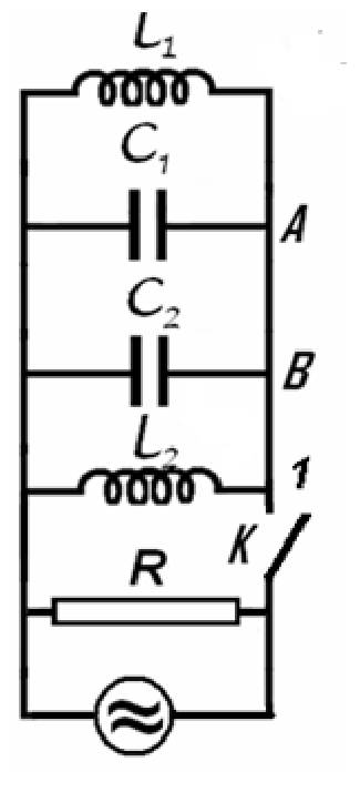
a. Find the ratio of frequency \(f_m\) for which the active power in circuit has the maximum value \(P_m\) and the frequency difference \(\Delta f=f_+-f_-\) of the frequencies \(f_+\) and \(f_-\) for which the active power in the circuit is half of the maximum power \(P_m\).
The switch \(K\) is now open. In the moment \(t_0\) immediately after the switch is open the intensities of the currents in the coils \(L_1\) and \(L_2\) are \(i_{01}=0{,}1\,A\) and \(i_{02}=0{,}2\,A\) (the currents flow as in the figure); at the same moment, the potential difference on the capacitor with capacity \(C_1\) is \(u_0=40\,V\) :
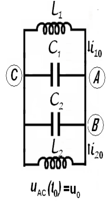
b. Calculate the frequency of electromagnetic oscillation in \(L_1C_1C_2L_2\) circuit;
c. Determine the intensity of the electric current in the \(AB\) conductor;
d. Calculate the amplitude of the oscillation of the intensity of electric current in the coil \(L_1\).
Neglect the mutual induction of the coils, and the electric resistance of the conductors. Neglect the fast transition phenomena occurring when the switch is closed or opened.
Official English text of the problem.
Answers
- a. \(\displaystyle \boxed{\frac{f_m}{\Delta f}=150}\), with \(f_m=15.9\,\mathrm{kHz}\) and \(\Delta f=106\,\mathrm{Hz}\).
- b. \(\boxed{f_0=15.9\,\mathrm{kHz}}\), corresponding to \(\omega_0=1.00\times10^5\,\mathrm{rad\,s^{-1}}\).
- c. \(\boxed{I_{AB}=0.100\,\mathrm A}\), constant and directed from \(B\) to \(A\).
- d. \(\boxed{I_{1,\mathrm{osc}}=0.204\,\mathrm A}\). The current oscillates about a mean of \(-0.100\,\mathrm A\), taking the indicated initial-current direction as positive.
Solution
a. Driven circuit: resonance and half-power bandwidth
With \(K\) closed, both capacitors, both inductors, and the resistor are connected in parallel. Their equivalent capacitance and inductance are \[ C=C_1+C_2=15\,\mathrm{nF}, \qquad L=\left(\frac1{L_1}+\frac1{L_2}\right)^{-1} =\frac{L_1L_2}{L_1+L_2} =6.6667\,\mathrm{mH}. \] The inductance formula uses the stipulated absence of mutual induction.
Let \(I\) be the constant rms source current and \(\omega=2\pi f\). The circuit admittance is \[ Y=\frac1R+\mathrm i\left(\omega C-\frac1{\omega L}\right). \] Only \(R\) dissipates active power. Since the rms voltage is \(I/|Y|\), \[ P(\omega) =\frac{I^2}{R|Y|^2} =\frac{I^2R} {1+R^2\left(\omega C-\frac1{\omega L}\right)^2}. \]
The maximum occurs when the reactive part of the admittance vanishes: \[ \omega_m C-\frac1{\omega_m L}=0. \] Consequently, \[ \omega_m=\frac1{\sqrt{LC}}, \qquad P_m=I^2R. \]
At either half-power frequency, \[ P=\frac{P_m}{2} \quad\Longrightarrow\quad \left|\omega C-\frac1{\omega L}\right|=\frac1R. \] The two positive solutions are \[ \omega_\pm =\sqrt{\omega_m^2+\frac1{4R^2C^2}} \pm\frac1{2RC}. \] Their difference is therefore exactly \[ \Delta\omega=\frac1{RC}, \qquad \Delta f=\frac1{2\pi RC}. \] No narrow-band approximation is needed.
Numerically, \[ LC=1.00\times10^{-10}\,\mathrm{s^2}, \] so \[ f_m=\frac{10^5}{2\pi} =1.59155\times10^4\,\mathrm{Hz}, \] and \[ \Delta f =\frac1{2\pi(10^5)(15\times10^{-9})} =106.103\,\mathrm{Hz}. \] Thus the requested ratio is \[ \boxed{\frac{f_m}{\Delta f} =\omega_m RC =R\sqrt{\frac CL} =150}. \]
b. Free electromagnetic oscillation
After the switch opens, the resistor and source no longer load the LC circuit. Under the stated idealizations, its oscillation is undamped.
Define \[ u(t)=V_A-V_C=V_B-V_C, \] and take both inductor currents \(i_1,i_2\) as positive from the left rail to the right rail. These agree with the indicated initial directions, so \[ i_1(t_0)=0.1\,\mathrm A,\qquad i_2(t_0)=0.2\,\mathrm A,\qquad u(t_0)=40\,\mathrm V. \]
The inductor voltage laws give \[ L_1\dot i_1=-u,\qquad L_2\dot i_2=-u. \] The total capacitor current from right to left is \(C\dot u\). Kirchhoff’s current law therefore gives \[ C\dot u=i_1+i_2. \] Differentiating, \[ C\ddot u =\dot i_1+\dot i_2 =-\left(\frac1{L_1}+\frac1{L_2}\right)u, \] or \[ \ddot u+\omega_0^2u=0, \qquad \omega_0^2=\frac1C\left(\frac1{L_1}+\frac1{L_2}\right) =\frac1{LC}. \] Hence \[ \boxed{\omega_0=1.00\times10^5\,\mathrm{rad\,s^{-1}}}, \qquad \boxed{f_0=\frac{\omega_0}{2\pi}=15.9\,\mathrm{kHz}}. \]
For the remaining parts, the initial voltage derivative is \[ \dot u(t_0)=\frac{i_{01}+i_{02}}C =\frac{0.3}{15\times10^{-9}} =2.00\times10^7\,\mathrm{V\,s^{-1}}. \] Writing \(\theta=\omega_0(t-t_0)\), the voltage is therefore \[ \boxed{u(t)=\bigl(40\cos\theta+200\sin\theta\bigr)\,\mathrm V}. \]
c. Current in conductor \(AB\)
Let \(j\) be the current in \(AB\), positive from \(A\) to \(B\). At \(A\), the incoming inductor current splits between \(C_1\) and \(AB\): \[ j=i_1-C_1\dot u. \] Its derivative is \[ \dot j =-\frac{u}{L_1}-C_1\ddot u =\left(C_1\omega_0^2-\frac1{L_1}\right)u. \]
For the given components, \[ L_1C_1=L_2C_2=1.00\times10^{-10}\,\mathrm{s^2}. \] This implies \[ \omega_0^2=\frac1{L_1C_1}=\frac1{L_2C_2}, \] and consequently \[ \dot j=0. \] Thus the current in \(AB\) is constant despite the oscillating capacitor voltage and coil currents.
Its value follows from the initial conditions: \[ j=i_{01}-C_1\frac{i_{01}+i_{02}}{C_1+C_2} =0.1-\frac{10}{15}(0.3) =-0.100\,\mathrm A. \] The negative sign reverses the chosen reference direction: \[ \boxed{I_{AB}=0.100\,\mathrm A,\quad\text{from }B\text{ to }A}. \]
d. Oscillation amplitude of the current in \(L_1\)
Using \(i_1=j+C_1\dot u\) and the results above, \[ \begin{aligned} i_1(t) &=-0.100 +C_1\omega_0\bigl(-40\sin\theta+200\cos\theta\bigr)\\ &=\bigl(-0.100+0.200\cos\theta-0.0400\sin\theta\bigr)\,\mathrm A. \end{aligned} \]
For an oscillatory term \(a\cos\theta+b\sin\theta\), the amplitude is \(\sqrt{a^2+b^2}\). Therefore, \[ \boxed{ I_{1,\mathrm{osc}} =\sqrt{(0.200)^2+(0.0400)^2} =0.20396\,\mathrm A \simeq0.204\,\mathrm A}. \]
The constant term represents a persistent circulating current supported by the ideal inductors. Thus \(0.204\,\mathrm A\) is the amplitude about the mean \(-0.100\,\mathrm A\); the signed current ranges from approximately \(-0.304\,\mathrm A\) to \(+0.104\,\mathrm A\).
The solution was checked against the official solution. Where this solution differs from the official solution, the official solution contains an error or a misprint.
IPhO 1983 · Theorieaufgabe 2
Eine andere Art von Schwingung
Wir betrachten den elektrischen Stromkreis in der Abbildung, für den \(L_1=10\,mH\), \(L_2=20\,mH\), \(C_1=10\,nF\), \(C_2=5\,nF\) und \(R=100\,k\Omega\) gelten. Bei geschlossenem Schalter \(K\) ist der Stromkreis an eine Wechselstromquelle angeschlossen. Der von der Quelle gelieferte Strom hat eine konstante Stromstärke, während seine Frequenz verändert werden kann.
a. Bestimmen Sie das Verhältnis der Frequenz \(f_m\), bei der die Wirkleistung im Stromkreis ihren Maximalwert \(P_m\) erreicht, zur Frequenzdifferenz \(\Delta f=f_+-f_-\) der Frequenzen \(f_+\) und \(f_-\), bei denen die Wirkleistung im Stromkreis die Hälfte der maximalen Leistung \(P_m\) beträgt.
Der Schalter \(K\) wird nun geöffnet. Zum Zeitpunkt \(t_0\) unmittelbar nach dem Öffnen des Schalters sind die Stromstärken in den Spulen \(L_1\) und \(L_2\) gleich \(i_{01}=0{,}1\,A\) und \(i_{02}=0{,}2\,A\) (die Ströme fließen wie in der Abbildung angegeben); zum selben Zeitpunkt beträgt die Spannung am Kondensator mit der Kapazität \(C_1\) genau \(u_0=40\,V\):
b. Berechnen Sie die Frequenz der elektromagnetischen Schwingung im Stromkreis \(L_1C_1C_2L_2\);
c. Bestimmen Sie die elektrische Stromstärke im Leiter \(AB\);
d. Berechnen Sie die Schwingungsamplitude der elektrischen Stromstärke in der Spule \(L_1\).
Vernachlässigen Sie die gegenseitige Induktion der Spulen und den elektrischen Widerstand der Leiter. Vernachlässigen Sie die schnellen Übergangsvorgänge beim Schließen oder Öffnen des Schalters.
Aufgabentext aus dem offiziellen englischen Text übersetzt.
Antworten
- a. \(\displaystyle \boxed{\frac{f_m}{\Delta f}=150}\), mit \(f_m=15.9\,\mathrm{kHz}\) und \(\Delta f=106\,\mathrm{Hz}\).
- b. \(\boxed{f_0=15.9\,\mathrm{kHz}}\), entsprechend \(\omega_0=1.00\times10^5\,\mathrm{rad\,s^{-1}}\).
- c. \(\boxed{I_{AB}=0.100\,\mathrm A}\), konstant und von \(B\) nach \(A\) gerichtet.
- d. \(\boxed{I_{1,\mathrm{osc}}=0.204\,\mathrm A}\). Die Stromstärke schwingt um einen Mittelwert von \(-0.100\,\mathrm A\), wobei die angegebene Richtung des Anfangsstroms als positiv gewählt wird.
Lösung
a. Angeregter Stromkreis: Resonanz und Halbwertsbreite der Leistung
Bei geschlossenem \(K\) sind beide Kondensatoren, beide Spulen und der Widerstand parallel geschaltet. Ihre Ersatzkapazität und Ersatzinduktivität betragen \[ C=C_1+C_2=15\,\mathrm{nF}, \qquad L=\left(\frac1{L_1}+\frac1{L_2}\right)^{-1} =\frac{L_1L_2}{L_1+L_2} =6.6667\,\mathrm{mH}. \] Die Formel für die Induktivität setzt voraus, dass gemäß der Aufgabenstellung keine gegenseitige Induktion vorliegt.
Es seien \(I\) der konstante Effektivwert des Quellenstroms und \(\omega=2\pi f\). Die Admittanz des Stromkreises ist \[ Y=\frac1R+\mathrm i\left(\omega C-\frac1{\omega L}\right). \] Nur in \(R\) wird Wirkleistung umgesetzt. Da der Effektivwert der Spannung \(I/|Y|\) beträgt, gilt \[ P(\omega) =\frac{I^2}{R|Y|^2} =\frac{I^2R} {1+R^2\left(\omega C-\frac1{\omega L}\right)^2}. \]
Das Maximum tritt auf, wenn der Blindanteil der Admittanz verschwindet: \[ \omega_m C-\frac1{\omega_m L}=0. \] Folglich gilt \[ \omega_m=\frac1{\sqrt{LC}}, \qquad P_m=I^2R. \]
Bei jeder der beiden Frequenzen mit halber Maximalleistung gilt \[ P=\frac{P_m}{2} \quad\Longrightarrow\quad \left|\omega C-\frac1{\omega L}\right|=\frac1R. \] Die beiden positiven Lösungen lauten \[ \omega_\pm =\sqrt{\omega_m^2+\frac1{4R^2C^2}} \pm\frac1{2RC}. \] Ihre Differenz beträgt daher exakt \[ \Delta\omega=\frac1{RC}, \qquad \Delta f=\frac1{2\pi RC}. \] Eine Schmalbandnäherung ist nicht erforderlich.
Numerisch ergibt sich \[ LC=1.00\times10^{-10}\,\mathrm{s^2}, \] also \[ f_m=\frac{10^5}{2\pi} =1.59155\times10^4\,\mathrm{Hz}, \] und \[ \Delta f =\frac1{2\pi(10^5)(15\times10^{-9})} =106.103\,\mathrm{Hz}. \] Damit ist das gesuchte Verhältnis \[ \boxed{\frac{f_m}{\Delta f} =\omega_m RC =R\sqrt{\frac CL} =150}. \]
b. Freie elektromagnetische Schwingung
Nach dem Öffnen des Schalters belasten der Widerstand und die Quelle den LC-Kreis nicht mehr. Unter den angegebenen idealisierenden Annahmen ist seine Schwingung ungedämpft.
Wir definieren \[ u(t)=V_A-V_C=V_B-V_C, \] und wählen für beide Spulenströme \(i_1,i_2\) die Richtung von der linken zur rechten Sammelleitung als positiv. Diese Richtungen stimmen mit den angegebenen Anfangsrichtungen überein, sodass \[ i_1(t_0)=0.1\,\mathrm A,\qquad i_2(t_0)=0.2\,\mathrm A,\qquad u(t_0)=40\,\mathrm V. \]
Die Spannungsgleichungen der Spulen liefern \[ L_1\dot i_1=-u,\qquad L_2\dot i_2=-u. \] Der gesamte Kondensatorstrom von rechts nach links beträgt \(C\dot u\). Die Kirchhoffsche Knotenregel ergibt daher \[ C\dot u=i_1+i_2. \] Durch Differenzieren folgt \[ C\ddot u =\dot i_1+\dot i_2 =-\left(\frac1{L_1}+\frac1{L_2}\right)u, \] oder \[ \ddot u+\omega_0^2u=0, \qquad \omega_0^2=\frac1C\left(\frac1{L_1}+\frac1{L_2}\right) =\frac1{LC}. \] Somit gilt \[ \boxed{\omega_0=1.00\times10^5\,\mathrm{rad\,s^{-1}}}, \qquad \boxed{f_0=\frac{\omega_0}{2\pi}=15.9\,\mathrm{kHz}}. \]
Für die verbleibenden Teilaufgaben benötigen wir die anfängliche zeitliche Ableitung der Spannung: \[ \dot u(t_0)=\frac{i_{01}+i_{02}}C =\frac{0.3}{15\times10^{-9}} =2.00\times10^7\,\mathrm{V\,s^{-1}}. \] Mit \(\theta=\omega_0(t-t_0)\) lautet die Spannung daher \[ \boxed{u(t)=\bigl(40\cos\theta+200\sin\theta\bigr)\,\mathrm V}. \]
c. Strom im Leiter \(AB\)
Es sei \(j\) die Stromstärke in \(AB\), positiv von \(A\) nach \(B\). Bei \(A\) teilt sich der zufließende Spulenstrom auf \(C_1\) und \(AB\) auf: \[ j=i_1-C_1\dot u. \] Seine zeitliche Ableitung ist \[ \dot j =-\frac{u}{L_1}-C_1\ddot u =\left(C_1\omega_0^2-\frac1{L_1}\right)u. \]
Für die gegebenen Bauteile gilt \[ L_1C_1=L_2C_2=1.00\times10^{-10}\,\mathrm{s^2}. \] Daraus folgt \[ \omega_0^2=\frac1{L_1C_1}=\frac1{L_2C_2}, \] und somit \[ \dot j=0. \] Die Stromstärke in \(AB\) ist also trotz der schwingenden Kondensatorspannung und Spulenströme konstant.
Ihr Wert folgt aus den Anfangsbedingungen: \[ j=i_{01}-C_1\frac{i_{01}+i_{02}}{C_1+C_2} =0.1-\frac{10}{15}(0.3) =-0.100\,\mathrm A. \] Das negative Vorzeichen kehrt die gewählte Bezugsrichtung um: \[ \boxed{I_{AB}=0.100\,\mathrm A,\quad\text{von }B\text{ nach }A}. \]
d. Schwingungsamplitude der Stromstärke in \(L_1\)
Mit \(i_1=j+C_1\dot u\) und den obigen Ergebnissen folgt \[ \begin{aligned} i_1(t) &=-0.100 +C_1\omega_0\bigl(-40\sin\theta+200\cos\theta\bigr)\\ &=\bigl(-0.100+0.200\cos\theta-0.0400\sin\theta\bigr)\,\mathrm A. \end{aligned} \]
Für einen schwingenden Term \(a\cos\theta+b\sin\theta\) beträgt die Amplitude \(\sqrt{a^2+b^2}\). Daher gilt \[ \boxed{ I_{1,\mathrm{osc}} =\sqrt{(0.200)^2+(0.0400)^2} =0.20396\,\mathrm A \simeq0.204\,\mathrm A}. \]
Der konstante Term beschreibt einen dauerhaften Kreisstrom, der von den idealen Spulen aufrechterhalten wird. Somit ist \(0.204\,\mathrm A\) die Amplitude um den Mittelwert \(-0.100\,\mathrm A\); die vorzeichenbehaftete Stromstärke reicht von ungefähr \(-0.304\,\mathrm A\) bis \(+0.104\,\mathrm A\).
Die Lösung wurde mit der offiziellen Lösung abgeglichen. Wo diese Lösung von der offiziellen Lösung abweicht, enthält die offizielle Lösung einen Fehler oder Druckfehler.
IPhO 1983 · Teori sorusu 2
Farklı bir salınım türü
Şekildeki elektrik devresini ele alalım; bu devrede \(L_1=10\,mH\), \(L_2=20\,mH\), \(C_1=10\,nF\), \(C_2=5\,nF\) ve \(R=100\,k\Omega\) değerlerindedir. \(K\) anahtarı kapalıyken devre bir alternatif akım kaynağına bağlıdır. Kaynağın sağladığı akımın şiddeti sabittir, frekansı ise değiştirilebilir.
a. Devredeki aktif gücün en büyük değeri \(P_m\)'ye ulaştığı \(f_m\) frekansının, devredeki aktif gücün en büyük güç \(P_m\)'nin yarısı olduğu \(f_+\) ve \(f_-\) frekansları arasındaki \(\Delta f=f_+-f_-\) farkına oranını bulunuz.
Şimdi \(K\) anahtarı açılıyor. Anahtarın açılmasından hemen sonraki \(t_0\) anında, \(L_1\) ve \(L_2\) bobinlerindeki akımların şiddetleri \(i_{01}=0{,}1\,A\) ve \(i_{02}=0{,}2\,A\)'dir (akımlar şekilde gösterilen yönlerde akar); aynı anda, sığası \(C_1\) olan kondansatörün uçları arasındaki potansiyel farkı \(u_0=40\,V\)'tur:
b. \(L_1C_1C_2L_2\) devresindeki elektromanyetik salınımın frekansını hesaplayınız;
c. \(AB\) iletkenindeki elektrik akımının şiddetini belirleyiniz;
d. \(L_1\) bobinindeki elektrik akımının şiddetinin salınım genliğini hesaplayınız.
Bobinlerin karşılıklı indüksiyonunu ve iletkenlerin elektriksel direncini ihmal ediniz. Anahtar kapatılırken veya açılırken meydana gelen hızlı geçiş olaylarını ihmal ediniz.
Soru metni resmi İngilizce metinden çevrilmiştir.
Cevaplar
- a. \(\displaystyle \boxed{\frac{f_m}{\Delta f}=150}\); burada \(f_m=15.9\,\mathrm{kHz}\) ve \(\Delta f=106\,\mathrm{Hz}\)'dir.
- b. \(\boxed{f_0=15.9\,\mathrm{kHz}}\); buna karşılık gelen açısal frekans \(\omega_0=1.00\times10^5\,\mathrm{rad\,s^{-1}}\)'dir.
- c. \(\boxed{I_{AB}=0.100\,\mathrm A}\), sabittir ve \(B\)'den \(A\)'ya yönelmiştir.
- d. \(\boxed{I_{1,\mathrm{osc}}=0.204\,\mathrm A}\). Gösterilen başlangıç akımı yönü pozitif alındığında akım, \(-0.100\,\mathrm A\) ortalama değeri etrafında salınır.
Çözüm
a. Zorlanmış devre: rezonans ve yarı güç bant genişliği
\(K\) kapalıyken her iki kondansatör, her iki bobin ve direnç paralel bağlıdır. Eşdeğer sığa ve indüktansları \[ C=C_1+C_2=15\,\mathrm{nF}, \qquad L=\left(\frac1{L_1}+\frac1{L_2}\right)^{-1} =\frac{L_1L_2}{L_1+L_2} =6.6667\,\mathrm{mH}. \] olarak bulunur. İndüktans formülünde, karşılıklı indüksiyonun bulunmadığı yönündeki varsayım kullanılmıştır.
Kaynak akımının sabit etkin değeri \(I\) ve \(\omega=2\pi f\) olsun. Devrenin admitansı \[ Y=\frac1R+\mathrm i\left(\omega C-\frac1{\omega L}\right). \] şeklindedir. Yalnızca \(R\) aktif güç harcar. Gerilimin etkin değeri \(I/|Y|\) olduğundan, \[ P(\omega) =\frac{I^2}{R|Y|^2} =\frac{I^2R} {1+R^2\left(\omega C-\frac1{\omega L}\right)^2}. \]
En büyük değer, admitansın reaktif kısmı sıfır olduğunda elde edilir: \[ \omega_m C-\frac1{\omega_m L}=0. \] Dolayısıyla, \[ \omega_m=\frac1{\sqrt{LC}}, \qquad P_m=I^2R. \]
Yarı güç frekanslarının her birinde, \[ P=\frac{P_m}{2} \quad\Longrightarrow\quad \left|\omega C-\frac1{\omega L}\right|=\frac1R. \] İki pozitif çözüm \[ \omega_\pm =\sqrt{\omega_m^2+\frac1{4R^2C^2}} \pm\frac1{2RC}. \] şeklindedir. Bu nedenle aralarındaki fark tam olarak \[ \Delta\omega=\frac1{RC}, \qquad \Delta f=\frac1{2\pi RC}. \] olur. Dar bant yaklaşımına gerek yoktur.
Sayısal olarak, \[ LC=1.00\times10^{-10}\,\mathrm{s^2}, \] olduğundan \[ f_m=\frac{10^5}{2\pi} =1.59155\times10^4\,\mathrm{Hz}, \] ve \[ \Delta f =\frac1{2\pi(10^5)(15\times10^{-9})} =106.103\,\mathrm{Hz}. \] Böylece istenen oran \[ \boxed{\frac{f_m}{\Delta f} =\omega_m RC =R\sqrt{\frac CL} =150}. \] olarak bulunur.
b. Serbest elektromanyetik salınım
Anahtar açıldıktan sonra direnç ve kaynak artık LC devresini yüklemez. Belirtilen idealleştirmeler altında devrenin salınımı sönümsüzdür.
Gerilimi \[ u(t)=V_A-V_C=V_B-V_C, \] olarak tanımlayalım ve her iki bobin akımı \(i_1,i_2\) için soldaki iletken hattan sağdaki iletken hatta doğru olan yönü pozitif alalım. Bu yönler gösterilen başlangıç yönleriyle aynıdır; dolayısıyla \[ i_1(t_0)=0.1\,\mathrm A,\qquad i_2(t_0)=0.2\,\mathrm A,\qquad u(t_0)=40\,\mathrm V. \]
Bobinlerin gerilim bağıntıları \[ L_1\dot i_1=-u,\qquad L_2\dot i_2=-u. \] sonucunu verir. Sağdan sola doğru toplam kondansatör akımı \(C\dot u\)'dur. Bu nedenle Kirchhoff'un akım yasası \[ C\dot u=i_1+i_2. \] sonucunu verir. Türev alındığında, \[ C\ddot u =\dot i_1+\dot i_2 =-\left(\frac1{L_1}+\frac1{L_2}\right)u, \] veya \[ \ddot u+\omega_0^2u=0, \qquad \omega_0^2=\frac1C\left(\frac1{L_1}+\frac1{L_2}\right) =\frac1{LC}. \] elde edilir. Böylece \[ \boxed{\omega_0=1.00\times10^5\,\mathrm{rad\,s^{-1}}}, \qquad \boxed{f_0=\frac{\omega_0}{2\pi}=15.9\,\mathrm{kHz}}. \]
Kalan kısımlarda kullanılacak olan gerilimin başlangıçtaki türevi \[ \dot u(t_0)=\frac{i_{01}+i_{02}}C =\frac{0.3}{15\times10^{-9}} =2.00\times10^7\,\mathrm{V\,s^{-1}}. \] şeklindedir. \(\theta=\omega_0(t-t_0)\) yazılırsa gerilim \[ \boxed{u(t)=\bigl(40\cos\theta+200\sin\theta\bigr)\,\mathrm V}. \] olarak bulunur.
c. \(AB\) iletkenindeki akım
\(AB\)'deki akım \(j\) olsun ve \(A\)'dan \(B\)'ye doğru olan yön pozitif alınsın. \(A\) noktasında, gelen bobin akımı \(C_1\) ile \(AB\) arasında bölünür: \[ j=i_1-C_1\dot u. \] Bu akımın türevi \[ \dot j =-\frac{u}{L_1}-C_1\ddot u =\left(C_1\omega_0^2-\frac1{L_1}\right)u. \] şeklindedir.
Verilen devre elemanları için, \[ L_1C_1=L_2C_2=1.00\times10^{-10}\,\mathrm{s^2}. \] Buradan \[ \omega_0^2=\frac1{L_1C_1}=\frac1{L_2C_2}, \] ve dolayısıyla \[ \dot j=0. \] elde edilir. Böylece kondansatör gerilimi ve bobin akımları salınmasına rağmen \(AB\)'deki akım sabittir.
Akımın değeri başlangıç koşullarından bulunur: \[ j=i_{01}-C_1\frac{i_{01}+i_{02}}{C_1+C_2} =0.1-\frac{10}{15}(0.3) =-0.100\,\mathrm A. \] Eksi işareti, akımın seçilen referans yönünün tersine aktığını gösterir: \[ \boxed{I_{AB}=0.100\,\mathrm A,\quad\text{başlangıç: }B\text{ bitiş: }A}. \]
d. \(L_1\)'deki akımın salınım genliği
\(i_1=j+C_1\dot u\) ve yukarıdaki sonuçlar kullanılarak, \[ \begin{aligned} i_1(t) &=-0.100 +C_1\omega_0\bigl(-40\sin\theta+200\cos\theta\bigr)\\ &=\bigl(-0.100+0.200\cos\theta-0.0400\sin\theta\bigr)\,\mathrm A. \end{aligned} \]
\(a\cos\theta+b\sin\theta\) biçimindeki bir salınım teriminin genliği \(\sqrt{a^2+b^2}\)'dir. Dolayısıyla, \[ \boxed{ I_{1,\mathrm{osc}} =\sqrt{(0.200)^2+(0.0400)^2} =0.20396\,\mathrm A \simeq0.204\,\mathrm A}. \]
Sabit terim, ideal bobinler sayesinde devrede sürekli dolaşan bir akımı temsil eder. Dolayısıyla \(0.204\,\mathrm A\), \(-0.100\,\mathrm A\) ortalama değeri etrafındaki salınımın genliğidir; işaretli akım değeri yaklaşık \(-0.304\,\mathrm A\) ile \(+0.104\,\mathrm A\) arasında değişir.
Çözüm, resmi çözümle karşılaştırılarak kontrol edildi. Bu çözümün resmi çözümden ayrıldığı yerlerde resmi çözümde bir hata ya da baskı hatası vardır.
IPhO 1983 · Problema teórico 2
Un tipo diferente de oscilación
Consideremos el circuito eléctrico de la figura, para el cual \(L_1=10\,mH\), \(L_2=20\,mH\), \(C_1=10\,nF\), \(C_2=5\,nF\) y \(R=100\,k\Omega\). Con el interruptor \(K\) cerrado, el circuito está conectado a una fuente de corriente alterna. La corriente suministrada por la fuente tiene una intensidad constante, mientras que su frecuencia puede variarse.
a. Halle el cociente entre la frecuencia \(f_m\) para la cual la potencia activa en el circuito alcanza su valor máximo \(P_m\) y la diferencia de frecuencias \(\Delta f=f_+-f_-\), donde \(f_+\) y \(f_-\) son las frecuencias para las cuales la potencia activa en el circuito es la mitad de la potencia máxima \(P_m\).
Ahora se abre el interruptor \(K\). En el instante \(t_0\), inmediatamente después de abrir el interruptor, las intensidades de las corrientes en las bobinas \(L_1\) y \(L_2\) son \(i_{01}=0{,}1\,A\) e \(i_{02}=0{,}2\,A\) (las corrientes circulan como se indica en la figura); en ese mismo instante, la diferencia de potencial en el condensador de capacidad \(C_1\) es \(u_0=40\,V\):
b. Calcule la frecuencia de oscilación electromagnética en el circuito \(L_1C_1C_2L_2\);
c. Determine la intensidad de la corriente eléctrica en el conductor \(AB\);
d. Calcule la amplitud de la oscilación de la intensidad de la corriente eléctrica en la bobina \(L_1\).
Desprecie la inducción mutua entre las bobinas y la resistencia eléctrica de los conductores. Desprecie los fenómenos transitorios rápidos que se producen al cerrar o abrir el interruptor.
Enunciado traducido del texto oficial en inglés.
Respuestas
- a. \(\displaystyle \boxed{\frac{f_m}{\Delta f}=150}\), con \(f_m=15.9\,\mathrm{kHz}\) y \(\Delta f=106\,\mathrm{Hz}\).
- b. \(\boxed{f_0=15.9\,\mathrm{kHz}}\), correspondiente a \(\omega_0=1.00\times10^5\,\mathrm{rad\,s^{-1}}\).
- c. \(\boxed{I_{AB}=0.100\,\mathrm A}\), constante y dirigida de \(B\) a \(A\).
- d. \(\boxed{I_{1,\mathrm{osc}}=0.204\,\mathrm A}\). La corriente oscila alrededor de un valor medio de \(-0.100\,\mathrm A\), tomando como positivo el sentido indicado de la corriente inicial.
Solución
a. Circuito forzado: resonancia y ancho de banda a media potencia
Con \(K\) cerrado, los dos condensadores, las dos bobinas y la resistencia están conectados en paralelo. Su capacidad y su inductancia equivalentes son \[ C=C_1+C_2=15\,\mathrm{nF}, \qquad L=\left(\frac1{L_1}+\frac1{L_2}\right)^{-1} =\frac{L_1L_2}{L_1+L_2} =6.6667\,\mathrm{mH}. \] La fórmula de la inductancia utiliza la ausencia de inducción mutua estipulada en el enunciado.
Sea \(I\) el valor eficaz constante de la corriente de la fuente y sea \(\omega=2\pi f\). La admitancia del circuito es \[ Y=\frac1R+\mathrm i\left(\omega C-\frac1{\omega L}\right). \] Solo \(R\) disipa potencia activa. Como el valor eficaz de la tensión es \(I/|Y|\), \[ P(\omega) =\frac{I^2}{R|Y|^2} =\frac{I^2R} {1+R^2\left(\omega C-\frac1{\omega L}\right)^2}. \]
El máximo se alcanza cuando se anula la parte reactiva de la admitancia: \[ \omega_m C-\frac1{\omega_m L}=0. \] Por consiguiente, \[ \omega_m=\frac1{\sqrt{LC}}, \qquad P_m=I^2R. \]
En cualquiera de las dos frecuencias de media potencia, \[ P=\frac{P_m}{2} \quad\Longrightarrow\quad \left|\omega C-\frac1{\omega L}\right|=\frac1R. \] Las dos soluciones positivas son \[ \omega_\pm =\sqrt{\omega_m^2+\frac1{4R^2C^2}} \pm\frac1{2RC}. \] Por tanto, su diferencia es exactamente \[ \Delta\omega=\frac1{RC}, \qquad \Delta f=\frac1{2\pi RC}. \] No se necesita ninguna aproximación de banda estrecha.
Numéricamente, \[ LC=1.00\times10^{-10}\,\mathrm{s^2}, \] por lo que \[ f_m=\frac{10^5}{2\pi} =1.59155\times10^4\,\mathrm{Hz}, \] y \[ \Delta f =\frac1{2\pi(10^5)(15\times10^{-9})} =106.103\,\mathrm{Hz}. \] Así, el cociente solicitado es \[ \boxed{\frac{f_m}{\Delta f} =\omega_m RC =R\sqrt{\frac CL} =150}. \]
b. Oscilación electromagnética libre
Tras abrir el interruptor, la resistencia y la fuente dejan de cargar el circuito LC. Bajo las idealizaciones indicadas, su oscilación no está amortiguada.
Definamos \[ u(t)=V_A-V_C=V_B-V_C, \] y tomemos como positivo para ambas corrientes de las bobinas \(i_1,i_2\) el sentido del conductor lateral izquierdo al derecho. Estos sentidos coinciden con los sentidos iniciales indicados, de modo que \[ i_1(t_0)=0.1\,\mathrm A,\qquad i_2(t_0)=0.2\,\mathrm A,\qquad u(t_0)=40\,\mathrm V. \]
Las relaciones entre tensión y corriente en las bobinas dan \[ L_1\dot i_1=-u,\qquad L_2\dot i_2=-u. \] La corriente total por los condensadores de derecha a izquierda es \(C\dot u\). Por tanto, la ley de corrientes de Kirchhoff da \[ C\dot u=i_1+i_2. \] Derivando, \[ C\ddot u =\dot i_1+\dot i_2 =-\left(\frac1{L_1}+\frac1{L_2}\right)u, \] o bien \[ \ddot u+\omega_0^2u=0, \qquad \omega_0^2=\frac1C\left(\frac1{L_1}+\frac1{L_2}\right) =\frac1{LC}. \] Por lo tanto, \[ \boxed{\omega_0=1.00\times10^5\,\mathrm{rad\,s^{-1}}}, \qquad \boxed{f_0=\frac{\omega_0}{2\pi}=15.9\,\mathrm{kHz}}. \]
Para los apartados restantes, la derivada inicial de la tensión es \[ \dot u(t_0)=\frac{i_{01}+i_{02}}C =\frac{0.3}{15\times10^{-9}} =2.00\times10^7\,\mathrm{V\,s^{-1}}. \] Escribiendo \(\theta=\omega_0(t-t_0)\), la tensión es, por tanto, \[ \boxed{u(t)=\bigl(40\cos\theta+200\sin\theta\bigr)\,\mathrm V}. \]
c. Corriente en el conductor \(AB\)
Sea \(j\) la corriente en \(AB\), positiva de \(A\) a \(B\). En \(A\), la corriente que llega de la bobina se reparte entre \(C_1\) y \(AB\): \[ j=i_1-C_1\dot u. \] Su derivada es \[ \dot j =-\frac{u}{L_1}-C_1\ddot u =\left(C_1\omega_0^2-\frac1{L_1}\right)u. \]
Para los componentes dados, \[ L_1C_1=L_2C_2=1.00\times10^{-10}\,\mathrm{s^2}. \] Esto implica \[ \omega_0^2=\frac1{L_1C_1}=\frac1{L_2C_2}, \] y, en consecuencia, \[ \dot j=0. \] Así, la corriente en \(AB\) es constante a pesar de que la tensión en los condensadores y las corrientes en las bobinas oscilan.
Su valor se obtiene a partir de las condiciones iniciales: \[ j=i_{01}-C_1\frac{i_{01}+i_{02}}{C_1+C_2} =0.1-\frac{10}{15}(0.3) =-0.100\,\mathrm A. \] El signo negativo indica el sentido opuesto al sentido de referencia elegido: \[ \boxed{I_{AB}=0.100\,\mathrm A,\quad\text{de }B\text{ a }A}. \]
d. Amplitud de oscilación de la corriente en \(L_1\)
Utilizando \(i_1=j+C_1\dot u\) y los resultados anteriores, \[ \begin{aligned} i_1(t) &=-0.100 +C_1\omega_0\bigl(-40\sin\theta+200\cos\theta\bigr)\\ &=\bigl(-0.100+0.200\cos\theta-0.0400\sin\theta\bigr)\,\mathrm A. \end{aligned} \]
Para un término oscilatorio \(a\cos\theta+b\sin\theta\), la amplitud es \(\sqrt{a^2+b^2}\). Por tanto, \[ \boxed{ I_{1,\mathrm{osc}} =\sqrt{(0.200)^2+(0.0400)^2} =0.20396\,\mathrm A \simeq0.204\,\mathrm A}. \]
El término constante representa una corriente circulante persistente sostenida por las bobinas ideales. Así, \(0.204\,\mathrm A\) es la amplitud respecto al valor medio \(-0.100\,\mathrm A\); la corriente con signo varía aproximadamente entre \(-0.304\,\mathrm A\) y \(+0.104\,\mathrm A\).
La solución se comprobó con la solución oficial. Donde esta solución difiere de la solución oficial, la solución oficial contiene un error o una errata.
IPhO 1983 · 理论题 2
不同类型的振荡
考虑图示电路,其中 \(L_1=10\,mH\)、\(L_2=20\,mH\)、\(C_1=10\,nF\)、\(C_2=5\,nF\),且 \(R=100\,k\Omega\)。闭合开关 \(K\) 后,电路与交流电源相连接。电源提供的电流强度保持不变,而电流的频率可以改变。
a. 求使电路中的有功功率达到最大值 \(P_m\) 的频率 \(f_m\) 与频率差 \(\Delta f=f_+-f_-\) 的比值,其中 \(f_+\) 和 \(f_-\) 为使电路中的有功功率等于最大功率 \(P_m\) 一半的两个频率。
现在断开开关 \(K\)。在开关刚断开后的瞬间 \(t_0\),线圈 \(L_1\) 和 \(L_2\) 中的电流强度分别为 \(i_{01}=0{,}1\,A\) 和 \(i_{02}=0{,}2\,A\)(电流方向如图所示);在同一瞬间,电容为 \(C_1\) 的电容器两端的电势差为 \(u_0=40\,V\):
b. 计算 \(L_1C_1C_2L_2\) 电路中电磁振荡的频率;
c. 确定导线 \(AB\) 中的电流强度;
d. 计算线圈 \(L_1\) 中电流强度的振荡振幅。
忽略线圈之间的互感和导线的电阻。忽略开关闭合或断开时发生的快速暂态过程。
题目译自官方英文原文。
答案
- a. \(\displaystyle \boxed{\frac{f_m}{\Delta f}=150}\),其中 \(f_m=15.9\,\mathrm{kHz}\),\(\Delta f=106\,\mathrm{Hz}\)。
- b. \(\boxed{f_0=15.9\,\mathrm{kHz}}\),对应的角频率为 \(\omega_0=1.00\times10^5\,\mathrm{rad\,s^{-1}}\)。
- c. \(\boxed{I_{AB}=0.100\,\mathrm A}\),为恒定电流,方向从 \(B\) 到 \(A\)。
- d. \(\boxed{I_{1,\mathrm{osc}}=0.204\,\mathrm A}\)。以图示初始电流方向为正方向,电流围绕平均值 \(-0.100\,\mathrm A\) 振荡。
解答
a. 受迫振荡电路:谐振与半功率带宽
当 \(K\) 闭合时,两个电容器、两个电感器和电阻均并联连接。它们的等效电容和等效电感为 \[ C=C_1+C_2=15\,\mathrm{nF}, \qquad L=\left(\frac1{L_1}+\frac1{L_2}\right)^{-1} =\frac{L_1L_2}{L_1+L_2} =6.6667\,\mathrm{mH}. \] 上述电感公式利用了题设中不存在互感的条件。
设 \(I\) 为电源电流的恒定有效值,且 \(\omega=2\pi f\)。电路的导纳为 \[ Y=\frac1R+\mathrm i\left(\omega C-\frac1{\omega L}\right). \] 只有 \(R\) 消耗有功功率。由于电压有效值为 \(I/|Y|\),有 \[ P(\omega) =\frac{I^2}{R|Y|^2} =\frac{I^2R} {1+R^2\left(\omega C-\frac1{\omega L}\right)^2}. \]
当导纳的无功部分为零时,功率达到最大值: \[ \omega_m C-\frac1{\omega_m L}=0. \] 因此, \[ \omega_m=\frac1{\sqrt{LC}}, \qquad P_m=I^2R. \]
在任一半功率频率处, \[ P=\frac{P_m}{2} \quad\Longrightarrow\quad \left|\omega C-\frac1{\omega L}\right|=\frac1R. \] 两个正解为 \[ \omega_\pm =\sqrt{\omega_m^2+\frac1{4R^2C^2}} \pm\frac1{2RC}. \] 因此,它们之差恰好为 \[ \Delta\omega=\frac1{RC}, \qquad \Delta f=\frac1{2\pi RC}. \] 这里不需要采用窄带近似。
代入数值得 \[ LC=1.00\times10^{-10}\,\mathrm{s^2}, \] 所以 \[ f_m=\frac{10^5}{2\pi} =1.59155\times10^4\,\mathrm{Hz}, \] 且 \[ \Delta f =\frac1{2\pi(10^5)(15\times10^{-9})} =106.103\,\mathrm{Hz}. \] 因此,所求比值为 \[ \boxed{\frac{f_m}{\Delta f} =\omega_m RC =R\sqrt{\frac CL} =150}. \]
b. 自由电磁振荡
开关断开后,电阻和电源不再对 LC 电路产生负载作用。在题设的理想化条件下,电路中的振荡是无阻尼的。
定义 \[ u(t)=V_A-V_C=V_B-V_C, \] 并将两个电感电流 \(i_1,i_2\) 的正方向均取为从左侧母线流向右侧母线。这与图示初始方向一致,因此 \[ i_1(t_0)=0.1\,\mathrm A,\qquad i_2(t_0)=0.2\,\mathrm A,\qquad u(t_0)=40\,\mathrm V. \]
由电感的电压关系得 \[ L_1\dot i_1=-u,\qquad L_2\dot i_2=-u. \] 从右向左流过电容器的总电流为 \(C\dot u\)。因此,由基尔霍夫电流定律得 \[ C\dot u=i_1+i_2. \] 对时间求导,得 \[ C\ddot u =\dot i_1+\dot i_2 =-\left(\frac1{L_1}+\frac1{L_2}\right)u, \] 即 \[ \ddot u+\omega_0^2u=0, \qquad \omega_0^2=\frac1C\left(\frac1{L_1}+\frac1{L_2}\right) =\frac1{LC}. \] 所以 \[ \boxed{\omega_0=1.00\times10^5\,\mathrm{rad\,s^{-1}}}, \qquad \boxed{f_0=\frac{\omega_0}{2\pi}=15.9\,\mathrm{kHz}}. \]
为求解其余各问,先求出初始时刻电压对时间的导数: \[ \dot u(t_0)=\frac{i_{01}+i_{02}}C =\frac{0.3}{15\times10^{-9}} =2.00\times10^7\,\mathrm{V\,s^{-1}}. \] 令 \(\theta=\omega_0(t-t_0)\),则电压为 \[ \boxed{u(t)=\bigl(40\cos\theta+200\sin\theta\bigr)\,\mathrm V}. \]
c. 导线 \(AB\) 中的电流
设 \(j\) 为 \(AB\) 中的电流,以从 \(A\) 到 \(B\) 为正方向。在 \(A\) 点,流入的电感电流分流至 \(C_1\) 和 \(AB\): \[ j=i_1-C_1\dot u. \] 其对时间的导数为 \[ \dot j =-\frac{u}{L_1}-C_1\ddot u =\left(C_1\omega_0^2-\frac1{L_1}\right)u. \]
对于给定的元件, \[ L_1C_1=L_2C_2=1.00\times10^{-10}\,\mathrm{s^2}. \] 由此可得 \[ \omega_0^2=\frac1{L_1C_1}=\frac1{L_2C_2}, \] 因而 \[ \dot j=0. \] 因此,尽管电容器两端的电压和线圈中的电流都在振荡,\(AB\) 中的电流仍保持恒定。
由初始条件可求得其值: \[ j=i_{01}-C_1\frac{i_{01}+i_{02}}{C_1+C_2} =0.1-\frac{10}{15}(0.3) =-0.100\,\mathrm A. \] 负号表示实际方向与所选参考方向相反: \[ \boxed{I_{AB}=0.100\,\mathrm A,\quad\text{从 }B\text{ 到 }A}. \]
d. \(L_1\) 中电流的振荡振幅
利用 \(i_1=j+C_1\dot u\) 及上述结果,得 \[ \begin{aligned} i_1(t) &=-0.100 +C_1\omega_0\bigl(-40\sin\theta+200\cos\theta\bigr)\\ &=\bigl(-0.100+0.200\cos\theta-0.0400\sin\theta\bigr)\,\mathrm A. \end{aligned} \]
对于振荡项 \(a\cos\theta+b\sin\theta\),其振幅为 \(\sqrt{a^2+b^2}\)。因此, \[ \boxed{ I_{1,\mathrm{osc}} =\sqrt{(0.200)^2+(0.0400)^2} =0.20396\,\mathrm A \simeq0.204\,\mathrm A}. \]
常数项表示由理想电感维持的持续环流。因此,\(0.204\,\mathrm A\) 是相对于平均值 \(-0.100\,\mathrm A\) 的振幅;带符号的电流值约在 \(-0.304\,\mathrm A\) 到 \(+0.104\,\mathrm A\) 之间变化。
解答已与官方解答核对。本解答与官方解答不同之处,均为官方解答中的错误或印刷错误。
IPhO 1983 · Теоретическая задача 2
Другой вид колебаний
Рассмотрим электрическую цепь, изображённую на рисунке, в которой \(L_1=10\,mH\), \(L_2=20\,mH\), \(C_1=10\,nF\), \(C_2=5\,nF\) и \(R=100\,k\Omega\). При замкнутом ключе \(K\) цепь подключена к источнику переменного тока. Сила тока, поступающего от источника, постоянна, а его частоту можно изменять.
a. Найдите отношение частоты \(f_m\), при которой активная мощность в цепи достигает максимального значения \(P_m\), к разности \(\Delta f=f_+-f_-\) частот \(f_+\) и \(f_-\), при которых активная мощность в цепи равна половине максимальной мощности \(P_m\).
Теперь ключ \(K\) разомкнут. В момент \(t_0\) непосредственно после размыкания ключа силы токов в катушках \(L_1\) и \(L_2\) равны \(i_{01}=0{,}1\,A\) и \(i_{02}=0{,}2\,A\) (направления токов показаны на рисунке); в тот же момент разность потенциалов на конденсаторе ёмкостью \(C_1\) составляет \(u_0=40\,V\):
b. Вычислите частоту электромагнитных колебаний в контуре \(L_1C_1C_2L_2\);
c. Определите силу электрического тока в проводнике \(AB\);
d. Вычислите амплитуду колебаний силы электрического тока в катушке \(L_1\).
Пренебрегите взаимной индукцией катушек и электрическим сопротивлением проводников. Пренебрегите быстрыми переходными процессами, возникающими при замыкании или размыкании ключа.
Условие переведено с официального английского текста.
Ответы
- a. \(\displaystyle \boxed{\frac{f_m}{\Delta f}=150}\), при этом \(f_m=15.9\,\mathrm{kHz}\) и \(\Delta f=106\,\mathrm{Hz}\).
- b. \(\boxed{f_0=15.9\,\mathrm{kHz}}\), что соответствует \(\omega_0=1.00\times10^5\,\mathrm{rad\,s^{-1}}\).
- c. \(\boxed{I_{AB}=0.100\,\mathrm A}\), ток постоянен и направлен от \(B\) к \(A\).
- d. \(\boxed{I_{1,\mathrm{osc}}=0.204\,\mathrm A}\). Ток колеблется около среднего значения \(-0.100\,\mathrm A\), если указанное направление начального тока принять за положительное.
Решение
a. Цепь с внешним источником: резонанс и ширина полосы на уровне половинной мощности
При замкнутом ключе \(K\) оба конденсатора, обе катушки индуктивности и резистор соединены параллельно. Их эквивалентные ёмкость и индуктивность равны \[ C=C_1+C_2=15\,\mathrm{nF}, \qquad L=\left(\frac1{L_1}+\frac1{L_2}\right)^{-1} =\frac{L_1L_2}{L_1+L_2} =6.6667\,\mathrm{mH}. \] В формуле для индуктивности учтено заданное условием отсутствие взаимной индукции.
Пусть \(I\) — постоянное действующее значение тока источника и \(\omega=2\pi f\). Комплексная проводимость цепи равна \[ Y=\frac1R+\mathrm i\left(\omega C-\frac1{\omega L}\right). \] Активная мощность выделяется только на \(R\). Поскольку действующее значение напряжения равно \(I/|Y|\), \[ P(\omega) =\frac{I^2}{R|Y|^2} =\frac{I^2R} {1+R^2\left(\omega C-\frac1{\omega L}\right)^2}. \]
Максимум достигается, когда реактивная составляющая проводимости обращается в нуль: \[ \omega_m C-\frac1{\omega_m L}=0. \] Следовательно, \[ \omega_m=\frac1{\sqrt{LC}}, \qquad P_m=I^2R. \]
На каждой из двух частот, соответствующих половинной мощности, \[ P=\frac{P_m}{2} \quad\Longrightarrow\quad \left|\omega C-\frac1{\omega L}\right|=\frac1R. \] Два положительных решения имеют вид \[ \omega_\pm =\sqrt{\omega_m^2+\frac1{4R^2C^2}} \pm\frac1{2RC}. \] Поэтому их разность в точности равна \[ \Delta\omega=\frac1{RC}, \qquad \Delta f=\frac1{2\pi RC}. \] Узкополосное приближение не требуется.
Численно получаем \[ LC=1.00\times10^{-10}\,\mathrm{s^2}, \] так что \[ f_m=\frac{10^5}{2\pi} =1.59155\times10^4\,\mathrm{Hz}, \] а \[ \Delta f =\frac1{2\pi(10^5)(15\times10^{-9})} =106.103\,\mathrm{Hz}. \] Таким образом, искомое отношение равно \[ \boxed{\frac{f_m}{\Delta f} =\omega_m RC =R\sqrt{\frac CL} =150}. \]
b. Свободные электромагнитные колебания
После размыкания ключа резистор и источник больше не нагружают LC-контур. При принятых идеализациях колебания в нём являются незатухающими.
Определим \[ u(t)=V_A-V_C=V_B-V_C, \] и примем направления токов в обеих катушках \(i_1,i_2\) от левой шины к правой за положительные. Они совпадают с указанными начальными направлениями, поэтому \[ i_1(t_0)=0.1\,\mathrm A,\qquad i_2(t_0)=0.2\,\mathrm A,\qquad u(t_0)=40\,\mathrm V. \]
Соотношения между напряжением и током для катушек дают \[ L_1\dot i_1=-u,\qquad L_2\dot i_2=-u. \] Суммарный ток через конденсаторы справа налево равен \(C\dot u\). Поэтому по первому закону Кирхгофа \[ C\dot u=i_1+i_2. \] Дифференцируя, получаем \[ C\ddot u =\dot i_1+\dot i_2 =-\left(\frac1{L_1}+\frac1{L_2}\right)u, \] или \[ \ddot u+\omega_0^2u=0, \qquad \omega_0^2=\frac1C\left(\frac1{L_1}+\frac1{L_2}\right) =\frac1{LC}. \] Отсюда \[ \boxed{\omega_0=1.00\times10^5\,\mathrm{rad\,s^{-1}}}, \qquad \boxed{f_0=\frac{\omega_0}{2\pi}=15.9\,\mathrm{kHz}}. \]
Для решения оставшихся пунктов найдём начальную производную напряжения: \[ \dot u(t_0)=\frac{i_{01}+i_{02}}C =\frac{0.3}{15\times10^{-9}} =2.00\times10^7\,\mathrm{V\,s^{-1}}. \] Обозначив \(\theta=\omega_0(t-t_0)\), получаем для напряжения \[ \boxed{u(t)=\bigl(40\cos\theta+200\sin\theta\bigr)\,\mathrm V}. \]
c. Ток в проводнике \(AB\)
Пусть \(j\) — ток в \(AB\), положительный в направлении от \(A\) к \(B\). В узле \(A\) входящий ток катушки разветвляется между \(C_1\) и \(AB\): \[ j=i_1-C_1\dot u. \] Его производная равна \[ \dot j =-\frac{u}{L_1}-C_1\ddot u =\left(C_1\omega_0^2-\frac1{L_1}\right)u. \]
Для заданных элементов \[ L_1C_1=L_2C_2=1.00\times10^{-10}\,\mathrm{s^2}. \] Из этого следует \[ \omega_0^2=\frac1{L_1C_1}=\frac1{L_2C_2}, \] и, следовательно, \[ \dot j=0. \] Таким образом, ток в \(AB\) постоянен, несмотря на колебания напряжения на конденсаторах и токов в катушках.
Его значение следует из начальных условий: \[ j=i_{01}-C_1\frac{i_{01}+i_{02}}{C_1+C_2} =0.1-\frac{10}{15}(0.3) =-0.100\,\mathrm A. \] Отрицательный знак означает, что ток направлен противоположно выбранному положительному направлению: \[ \boxed{I_{AB}=0.100\,\mathrm A,\quad\text{от }B\text{ к }A}. \]
d. Амплитуда колебаний тока в \(L_1\)
Используя \(i_1=j+C_1\dot u\) и полученные выше результаты, находим \[ \begin{aligned} i_1(t) &=-0.100 +C_1\omega_0\bigl(-40\sin\theta+200\cos\theta\bigr)\\ &=\bigl(-0.100+0.200\cos\theta-0.0400\sin\theta\bigr)\,\mathrm A. \end{aligned} \]
Для колебательного слагаемого \(a\cos\theta+b\sin\theta\) амплитуда равна \(\sqrt{a^2+b^2}\). Поэтому \[ \boxed{ I_{1,\mathrm{osc}} =\sqrt{(0.200)^2+(0.0400)^2} =0.20396\,\mathrm A \simeq0.204\,\mathrm A}. \]
Постоянное слагаемое соответствует незатухающему циркулирующему току, поддерживаемому идеальными катушками индуктивности. Таким образом, \(0.204\,\mathrm A\) — амплитуда относительно среднего значения \(-0.100\,\mathrm A\); ток с учётом знака изменяется приблизительно от \(-0.304\,\mathrm A\) до \(+0.104\,\mathrm A\).
Решение проверено по официальному решению. Там, где это решение расходится с официальным, в официальном решении есть ошибка или опечатка.
IPhO 1983 · مسألة نظرية 2
نوع مختلف من الاهتزاز
لننظر في الدارة الكهربائية المبينة في الشكل، حيث \(L_1=10\,mH\)، و\(L_2=20\,mH\)، و\(C_1=10\,nF\)، و\(C_2=5\,nF\)، و\(R=100\,k\Omega\). عند إغلاق المفتاح \(K\)، تُوصَل الدارة بمصدر تيار متناوب. تكون شدة التيار الذي يزوده المصدر ثابتة، في حين يمكن تغيير تردد التيار.
a. أوجد النسبة بين التردد \(f_m\)، الذي تبلغ عنده القدرة الفعالة في الدارة قيمتها العظمى \(P_m\)، وفرق الترددين \(\Delta f=f_+-f_-\)، حيث \(f_+\) و\(f_-\) هما الترددان اللذان تكون عندهما القدرة الفعالة في الدارة نصف القدرة العظمى \(P_m\).
يُفتح الآن المفتاح \(K\). عند اللحظة \(t_0\) التي تلي فتح المفتاح مباشرة، تكون شدتا التيارين في الملفين \(L_1\) و\(L_2\) هما \(i_{01}=0{,}1\,A\) و\(i_{02}=0{,}2\,A\) على الترتيب (يسري التياران كما هو مبين في الشكل)؛ وعند اللحظة نفسها، يكون فرق الجهد بين طرفي المكثف ذي السعة \(C_1\) هو \(u_0=40\,V\):
b. احسب تردد الاهتزاز الكهرومغناطيسي في الدارة \(L_1C_1C_2L_2\)؛
c. حدد شدة التيار الكهربائي في الموصل \(AB\)؛
d. احسب سعة اهتزاز شدة التيار الكهربائي في الملف \(L_1\).
أهمل الحث المتبادل بين الملفين والمقاومة الكهربائية للموصلات. وأهمل الظواهر العابرة السريعة التي تحدث عند إغلاق المفتاح أو فتحه.
نص المسألة مترجم عن النص الإنجليزي الرسمي.
الإجابات
- a. \(\displaystyle \boxed{\frac{f_m}{\Delta f}=150}\)، حيث \(f_m=15.9\,\mathrm{kHz}\) و\(\Delta f=106\,\mathrm{Hz}\).
- b. \(\boxed{f_0=15.9\,\mathrm{kHz}}\)، وهو ما يقابل \(\omega_0=1.00\times10^5\,\mathrm{rad\,s^{-1}}\).
- c. \(\boxed{I_{AB}=0.100\,\mathrm A}\)، وهو ثابت ويتجه من \(B\) إلى \(A\).
- d. \(\boxed{I_{1,\mathrm{osc}}=0.204\,\mathrm A}\). يتذبذب التيار حول قيمة متوسطة مقدارها \(-0.100\,\mathrm A\)، مع اتخاذ اتجاه التيار الابتدائي المبين اتجاهًا موجبًا.
الحل
a. الدارة ذات الاهتزاز القسري: الرنين وعرض نطاق نصف القدرة
عند إغلاق \(K\)، يكون المكثفان والملفان والمقاومة موصولة جميعًا على التوازي. وتكون السعة المكافئة والمحاثة المكافئة كما يلي: \[ C=C_1+C_2=15\,\mathrm{nF}, \qquad L=\left(\frac1{L_1}+\frac1{L_2}\right)^{-1} =\frac{L_1L_2}{L_1+L_2} =6.6667\,\mathrm{mH}. \] تستند صيغة المحاثة إلى الافتراض المنصوص عليه بعدم وجود حث متبادل.
لتكن \(I\) القيمة الفعالة الثابتة لتيار المصدر، ولتكن \(\omega=2\pi f\). تكون المطاوعة الكهربائية للدارة: \[ Y=\frac1R+\mathrm i\left(\omega C-\frac1{\omega L}\right). \] المقاومة \(R\) وحدها هي التي تبدد القدرة الفعالة. وبما أن القيمة الفعالة للجهد هي \(I/|Y|\)، فإن: \[ P(\omega) =\frac{I^2}{R|Y|^2} =\frac{I^2R} {1+R^2\left(\omega C-\frac1{\omega L}\right)^2}. \]
تبلغ القدرة قيمتها العظمى عندما ينعدم الجزء التفاعلي من المطاوعة: \[ \omega_m C-\frac1{\omega_m L}=0. \] ومن ثم: \[ \omega_m=\frac1{\sqrt{LC}}, \qquad P_m=I^2R. \]
عند أي من ترددي نصف القدرة: \[ P=\frac{P_m}{2} \quad\Longrightarrow\quad \left|\omega C-\frac1{\omega L}\right|=\frac1R. \] الحلان الموجبان هما: \[ \omega_\pm =\sqrt{\omega_m^2+\frac1{4R^2C^2}} \pm\frac1{2RC}. \] ولذلك يكون الفرق بينهما، على نحو دقيق: \[ \Delta\omega=\frac1{RC}, \qquad \Delta f=\frac1{2\pi RC}. \] لا حاجة إلى استخدام تقريب النطاق الضيق.
عدديًا: \[ LC=1.00\times10^{-10}\,\mathrm{s^2}, \] ومن ثم: \[ f_m=\frac{10^5}{2\pi} =1.59155\times10^4\,\mathrm{Hz}, \] وكذلك: \[ \Delta f =\frac1{2\pi(10^5)(15\times10^{-9})} =106.103\,\mathrm{Hz}. \] إذن النسبة المطلوبة هي: \[ \boxed{\frac{f_m}{\Delta f} =\omega_m RC =R\sqrt{\frac CL} =150}. \]
b. الاهتزاز الكهرومغناطيسي الحر
بعد فتح المفتاح، لا تعود المقاومة والمصدر يشكلان حملًا على دارة LC. وفي ظل الافتراضات المثالية المذكورة، يكون اهتزازها غير مخمد.
نعرّف: \[ u(t)=V_A-V_C=V_B-V_C, \] ونتخذ الاتجاه من السلك الأيسر إلى السلك الأيمن اتجاهًا موجبًا لكلا تياري الملفين \(i_1,i_2\). يتفق هذان الاتجاهان مع الاتجاهين الابتدائيين المبينين، ولذلك: \[ i_1(t_0)=0.1\,\mathrm A,\qquad i_2(t_0)=0.2\,\mathrm A,\qquad u(t_0)=40\,\mathrm V. \]
تعطي علاقات الجهد في الملفين: \[ L_1\dot i_1=-u,\qquad L_2\dot i_2=-u. \] التيار الكلي في المكثفين من اليمين إلى اليسار هو \(C\dot u\). ولذلك يعطي قانون كيرشوف للتيار: \[ C\dot u=i_1+i_2. \] بالتفاضل: \[ C\ddot u =\dot i_1+\dot i_2 =-\left(\frac1{L_1}+\frac1{L_2}\right)u, \] أو: \[ \ddot u+\omega_0^2u=0, \qquad \omega_0^2=\frac1C\left(\frac1{L_1}+\frac1{L_2}\right) =\frac1{LC}. \] وعليه: \[ \boxed{\omega_0=1.00\times10^5\,\mathrm{rad\,s^{-1}}}, \qquad \boxed{f_0=\frac{\omega_0}{2\pi}=15.9\,\mathrm{kHz}}. \]
لاستخدامها في الأجزاء المتبقية، تكون القيمة الابتدائية لمشتقة الجهد: \[ \dot u(t_0)=\frac{i_{01}+i_{02}}C =\frac{0.3}{15\times10^{-9}} =2.00\times10^7\,\mathrm{V\,s^{-1}}. \] بوضع \(\theta=\omega_0(t-t_0)\)، يكون الجهد إذن: \[ \boxed{u(t)=\bigl(40\cos\theta+200\sin\theta\bigr)\,\mathrm V}. \]
c. التيار في الموصل \(AB\)
ليكن \(j\) التيار في \(AB\)، مع اتخاذ الاتجاه من \(A\) إلى \(B\) اتجاهًا موجبًا. عند \(A\)، يتفرع تيار الملف الوارد بين \(C_1\) و\(AB\): \[ j=i_1-C_1\dot u. \] وتكون مشتقته: \[ \dot j =-\frac{u}{L_1}-C_1\ddot u =\left(C_1\omega_0^2-\frac1{L_1}\right)u. \]
بالنسبة إلى العناصر المعطاة: \[ L_1C_1=L_2C_2=1.00\times10^{-10}\,\mathrm{s^2}. \] وهذا يعني أن: \[ \omega_0^2=\frac1{L_1C_1}=\frac1{L_2C_2}, \] وبالتالي: \[ \dot j=0. \] إذن التيار في \(AB\) ثابت على الرغم من تذبذب جهد المكثفين وتياري الملفين.
تُستنتج قيمته من الشروط الابتدائية: \[ j=i_{01}-C_1\frac{i_{01}+i_{02}}{C_1+C_2} =0.1-\frac{10}{15}(0.3) =-0.100\,\mathrm A. \] تعني الإشارة السالبة أن الاتجاه معاكس للاتجاه المرجعي المختار: \[ \boxed{I_{AB}=0.100\,\mathrm A,\quad\text{من }B\text{ إلى }A}. \]
d. سعة اهتزاز التيار في \(L_1\)
باستخدام \(i_1=j+C_1\dot u\) والنتائج السابقة: \[ \begin{aligned} i_1(t) &=-0.100 +C_1\omega_0\bigl(-40\sin\theta+200\cos\theta\bigr)\\ &=\bigl(-0.100+0.200\cos\theta-0.0400\sin\theta\bigr)\,\mathrm A. \end{aligned} \]
بالنسبة إلى حد اهتزازي من الشكل \(a\cos\theta+b\sin\theta\)، تكون السعة \(\sqrt{a^2+b^2}\). ولذلك: \[ \boxed{ I_{1,\mathrm{osc}} =\sqrt{(0.200)^2+(0.0400)^2} =0.20396\,\mathrm A \simeq0.204\,\mathrm A}. \]
يمثل الحد الثابت تيارًا دورانيًا مستمرًا تدعمه الملفات المثالية. وبذلك تكون \(0.204\,\mathrm A\) هي السعة حول القيمة المتوسطة \(-0.100\,\mathrm A\)؛ وتتراوح قيمة التيار الجبرية تقريبًا بين \(-0.304\,\mathrm A\) و\(+0.104\,\mathrm A\).
تمت مراجعة الحل بمقارنته بالحل الرسمي. حيثما يختلف هذا الحل عن الحل الرسمي، يحتوي الحل الرسمي على خطأ أو خطأ مطبعي.