IPhO 1982 · Theory problem 1
Fluorescent lamp
An alternating voltage of 50 Hz frequency is applied to the fluorescent lamp shown in the accompanying circuit diagram.
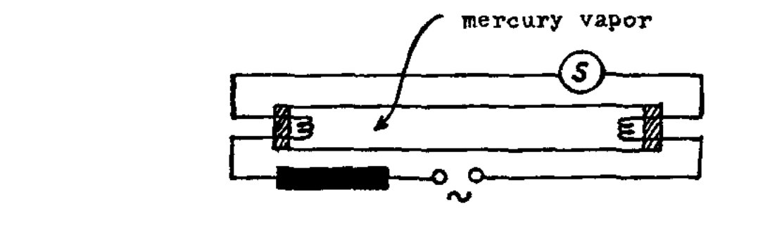
The following quantities are measured:
| overall voltage (main voltage) | \(U = 228.5\ \mathrm{V}\) |
| electric current | \(I = 0.6\ \mathrm{A}\) |
| partial voltage across the fluorescent lamp | \(U' = 84\ \mathrm{V}\) |
| ohmic resistance of the series reactor | \(R_{\mathrm d} = 26.3\ \Omega\) |
The fluorescent lamp itself may be considered as an ohmic resistor in the calculations.
a) What is the inductance \(L\) of the series reactor?
b) What is the phase shift \(\varphi\) between voltage and current?
c) What is the active power \(P_{\mathrm w}\) transformed by the apparatus?
d) Apart from limiting the current the series reactor has another important function. Name and explain this function!
Hint: The starter
includes a contact which closes shortly after switching on the lamp, opens up again and stays open.
e) In a diagram with a quantitative time scale sketch the time sequence of the luminous flux emitted by the lamp.
f) Why has the lamp to be ignited only once although the applied alternating voltage goes through zero in regular intervals?
g) According to the statement of the manufacturer, for a fluorescent lamp of the described type a capacitor of about \(4.7\ \mu\mathrm{F}\) can be switched in series with the series reactor. How does this affect the operation of the lamp and to what intent is this possibility provided for?
h) Examine both halves of the displayed demonstrator lamp with the added spectroscope. Explain the differences between the two spectra. You may walk up to the lamp and you may keep the spectroscope as a souvenir.
Official English text of the problem.
Answers
- a) \(\boxed{L \approx 1.09\ \mathrm{H}}\).
- b) \(\boxed{\varphi \approx 64.1^\circ}\), with the current lagging the mains voltage.
- c) \(\boxed{P_{\mathrm w}\approx 59.9\ \mathrm{W}}\): \(50.4\ \mathrm{W}\) in the lamp and \(9.47\ \mathrm{W}\) in the reactor resistance.
- d) The reactor produces the high-voltage ignition pulse by self-induction when the starter opens after preheating the electrodes.
- e) The luminous flux pulsates at \(\boxed{100\ \mathrm{Hz}}\), repeating every \(\boxed{10\ \mathrm{ms}}\). An idealized sketch is \(\Phi(t)\propto\sin^2(2\pi\,50t-\varphi)\).
- f) Residual ionization and hot electrodes allow the discharge to resume after each brief current zero without another cold-start ignition pulse.
- g) The capacitor approximately preserves the current and mean brightness while making the current lead the voltage. For \(4.7\ \mu\mathrm{F}\), \(I_C\approx0.611\ \mathrm{A}\), leading by \(63.6^\circ\). Pairing this lamp with an unmodified lamp gives nearly unity overall power factor and reduces flicker and stroboscopic effects.
- h) Assuming the demonstrator has uncoated and phosphor-coated halves: the uncoated half shows discrete mercury emission lines; the coated half additionally shows broad visible phosphor emission, produced by conversion of ultraviolet radiation into visible light.
Solution
The measured voltages and current are taken to be RMS values. During normal operation the starter is open. We use the stated ohmic approximation for the lamp and model the reactor as an ideal inductance in series with its winding resistance.
a) Inductance of the series reactor
The lamp resistance is \[ R_{\mathrm{lamp}}=\frac{U'}{I} =\frac{84}{0.6}=140\ \Omega. \] Thus the total series resistance is \[ R=R_{\mathrm{lamp}}+R_{\mathrm d} =140+26.3=166.3\ \Omega. \]
The resistive voltage is in phase with the current, while the inductive voltage leads the current by \(90^\circ\). Consequently, the RMS voltages obey the phasor relation \[ U^2=(IR)^2+(I\omega L)^2, \qquad \omega=2\pi f. \] The total resistive voltage is \[ IR=U'+IR_{\mathrm d} =84+0.6(26.3)=99.78\ \mathrm V. \] Hence the inductive voltage is \[ U_L=\sqrt{228.5^2-99.78^2} =205.56\ \mathrm V, \] and \[ L=\frac{U_L}{2\pi fI} =\frac{205.56}{2\pi(50)(0.6)} =\boxed{1.09\ \mathrm H}. \]
The corresponding inductive reactance is \[ X_L=\omega L=\boxed{342.6\ \Omega}. \]
b) Phase shift
For a series resistance and inductance, \[ \tan\varphi=\frac{X_L}{R}, \] so \[ \varphi=\tan^{-1}\!\left(\frac{342.6}{166.3}\right) =\boxed{64.1^\circ}. \] The current lags the applied voltage. Equivalently, \[ \cos\varphi=\frac{IR}{U} =\frac{99.78}{228.5} =0.4367. \]
With the time origin at a rising zero crossing of the mains voltage, \[ u(t)=\sqrt2\,U\sin\omega t, \qquad i(t)=\sqrt2\,I\sin(\omega t-\varphi). \]
c) Active power
An ideal inductance stores and returns energy, consuming no average power. The active power is therefore dissipated in the lamp and the winding resistance: \[ P_{\mathrm w}=I^2(R_{\mathrm{lamp}}+R_{\mathrm d}). \] Numerically, \[ P_{\mathrm w}=0.6^2(166.3) =59.868\ \mathrm W \approx\boxed{59.9\ \mathrm W}. \]
Its two contributions are \[ P_{\mathrm{lamp}}=U'I=84(0.6) =\boxed{50.4\ \mathrm W}, \] \[ P_{\mathrm d}=I^2R_{\mathrm d} =0.6^2(26.3) =\boxed{9.47\ \mathrm W}. \] This agrees with \(P_{\mathrm w}=UI\cos\varphi\).
d) Ignition by self-induction
When the starter closes, current flows through the reactor, the two electrode filaments, and the starter contact. This heats the electrodes, facilitating electron emission.
When the starter subsequently opens, the reactor opposes the rapid decrease of current. Faraday’s law gives its induced emf: \[ \mathcal E_L=-L\frac{di}{dt}. \] A rapid interruption therefore produces a large voltage pulse across the lamp. This pulse initiates electrical breakdown of the gas and establishes the discharge. Energy stored in the reactor’s magnetic field, \[ E_L=\frac12Li^2, \] is available during this transient.
Once the discharge is established, the starter remains open and the reactor limits the operating current. The magnitude of the ignition pulse cannot be calculated from the supplied data because the interruption time and transient circuit properties are unspecified.
e) Time dependence of the luminous flux
For an idealized sketch, assume constant luminous efficacy and neglect the phosphor’s emission delay. The luminous flux is then proportional to the instantaneous power delivered to the lamp: \[ p_{\mathrm{lamp}}(t) =R_{\mathrm{lamp}}i^2(t) =2R_{\mathrm{lamp}}I^2\sin^2(\omega t-\varphi). \] Here, \[ p_{\mathrm{lamp}}(t) =(100.8\ \mathrm W)\sin^2(\omega t-\varphi). \]
Thus \[ \boxed{\Phi(t)=\Phi_{\max}\sin^2(\omega t-\varphi)} =\frac{\Phi_{\max}}2 \left[1-\cos(2\omega t-2\varphi)\right]. \] Both current directions produce light, so the luminous-flux period is \[ T_{\Phi}=\frac{1}{2f} =\boxed{10\ \mathrm{ms}}, \] corresponding to \(\boxed{100\ \mathrm{Hz}}\).
For the sketch, choose a local time \(\tau=0\) at a current zero. Draw a smooth, nonnegative curve through these points and repeat it every \(10\ \mathrm{ms}\):
| \(\tau\) (\(\mathrm{ms}\)) | 0 | 2.5 | 5.0 | 7.5 | 10.0 |
|---|---|---|---|---|---|
| \(\Phi/\Phi_{\max}\) | 0 | \(1/2\) | 1 | \(1/2\) | 0 |
The curve has horizontal tangents at its minima and maxima. Its mean is \(\Phi_{\max}/2\).
Relative to the mains-voltage time origin used in part (b), the first current zero occurs at \[ t=\frac{\varphi}{\omega}=3.56\ \mathrm{ms}. \] Accordingly, ideal light minima occur at \(3.56,\ 13.56,\ldots\ \mathrm{ms}\), and maxima at \(8.56,\ 18.56,\ldots\ \mathrm{ms}\).
The absolute luminous flux is undetermined because no luminous efficacy is supplied. In a real lamp, phosphor persistence smooths and delays the light output, so its minima need not reach zero.
f) Why a fresh ignition pulse is unnecessary
The large starting voltage is needed to establish a discharge in the initially weakly ionized gas. During operation, the gas contains charged particles and the electrodes remain hot.
Around each current zero, the interruption is too brief for complete loss of ionization and cooling of the electrodes. The discharge can therefore resume in the next half-cycle at a much lower voltage than was required for the initial cold start.
Also, the source-voltage zeros and current zeros do not coincide because of the phase shift. Nevertheless, the current does cross zero every \(10\ \mathrm{ms}\); residual ionization and the heated electrodes explain why another starter pulse is unnecessary.
g) Effect and purpose of the series capacitor
With a capacitor in series, the impedance becomes \[ Z_C=R+j\left(\omega L-\frac{1}{\omega C}\right). \] For \(C=4.7\ \mu\mathrm F\), \[ X_C=\frac{1}{2\pi(50)(4.7\times10^{-6})} =677.3\ \Omega. \] The net reactance is therefore \[ X_{\mathrm{net}}=342.6-677.3 =-334.6\ \Omega. \] It is capacitive and has almost the same magnitude as the original inductive reactance.
The new current is \[ I_C=\frac{U}{\sqrt{R^2+X_{\mathrm{net}}^2}} =\frac{228.5}{\sqrt{166.3^2+334.6^2}} =\boxed{0.611\ \mathrm A}. \] The impedance phase is \[ \varphi_C=\tan^{-1}\!\left(\frac{-334.6}{166.3}\right) =-63.6^\circ, \] so the current now leads the voltage by \(\boxed{63.6^\circ}\).
The lamp power becomes \[ P_{\mathrm{lamp},C}=I_C^2R_{\mathrm{lamp}} \approx52.3\ \mathrm W, \] close to its original \(50.4\ \mathrm W\). Thus its mean brightness is approximately preserved.
To see why this capacitance was chosen, require the current magnitude to remain exactly unchanged: \[ (X_L-X_C)^2=X_L^2. \] The nonzero solution is \[ X_C=2X_L, \] giving \[ C_*=\frac{1}{2\omega X_L} =\frac{1}{2\omega^2L} =\boxed{4.65\ \mu\mathrm F}, \] which agrees with the manufacturer’s approximate \(4.7\ \mu\mathrm F\). At this value, the impedance changes from \(R+jX_L\) to \(R-jX_L\).
This permits a useful two-lamp arrangement: connect two lamp branches in parallel across the supply, one with the original reactor and one with the reactor plus series capacitor.
-
Power-factor improvement. For the ideal equal-current case, the two currents lag and lead by equal angles. Their reactive components cancel: \[ \underline I_{\mathrm{total}} =\frac{U}{R+jX_L}+\frac{U}{R-jX_L} =\frac{2UR}{R^2+X_L^2}. \] The total current is in phase with the voltage, giving unity power factor. With the nominal \(4.7\ \mu\mathrm F\), cancellation is nearly complete.
-
Reduced light modulation. The lamps reach their light minima at different times. Under the model of part (e), their combined flux is \[ \begin{aligned} \Phi_{\mathrm{pair}}(t) &=\Phi_{\max}\left[ \sin^2(\omega t-\varphi)+\sin^2(\omega t+\varphi)\right]\\ &=\Phi_{\max}\left[1-\cos(2\varphi)\cos(2\omega t)\right]. \end{aligned} \] Since \(|\cos(2\varphi)|\approx0.619<1\), the combined light never falls to zero in this model. Flicker and stroboscopic effects are reduced, although the light is not perfectly constant.
h) Spectra of the two halves
The expected interpretation is that the demonstrator has one uncoated half and one half coated with fluorescent phosphor.
In the uncoated half, the observed visible light comes directly from the mercury discharge. Excited mercury atoms emit photons at discrete transition energies, \[ h\nu=E_{\mathrm{upper}}-E_{\mathrm{lower}}, \] so the spectroscope shows separated emission lines. Much of the discharge radiation is ultraviolet and is therefore invisible to the eye.
In the phosphor-coated half, the coating absorbs ultraviolet radiation and re-emits part of its energy as visible light. This fluorescence produces broad visible emission bands, often appearing nearly continuous in a simple spectroscope. Direct mercury lines can remain superposed on this broader emission.
The coating therefore increases the useful visible output and changes its colour toward white. The spectral difference results from ultraviolet-to-visible conversion in the phosphor.
The solution was checked against the official solution.
IPhO 1982 · Theorieaufgabe 1
Leuchtstofflampe
An die im beigefügten Schaltbild dargestellte Leuchtstofflampe wird eine Wechselspannung mit einer Frequenz von 50 Hz angelegt.
Die folgenden Größen werden gemessen:
| Gesamtspannung (Netzspannung) | \(U = 228.5\ \mathrm{V}\) |
| Stromstärke | \(I = 0.6\ \mathrm{A}\) |
| Teilspannung an der Leuchtstofflampe | \(U' = 84\ \mathrm{V}\) |
| ohmscher Widerstand der Vorschaltdrossel | \(R_{\mathrm d} = 26.3\ \Omega\) |
Die Leuchtstofflampe selbst darf bei den Berechnungen als ohmscher Widerstand betrachtet werden.
a) Wie groß ist die Induktivität \(L\) der Vorschaltdrossel?
b) Wie groß ist die Phasenverschiebung \(\varphi\) zwischen Spannung und Strom?
c) Wie groß ist die von der Anordnung umgesetzte Wirkleistung \(P_{\mathrm w}\)?
d) Neben der Strombegrenzung hat die Vorschaltdrossel noch eine weitere wichtige Funktion. Nennen und erläutern Sie diese Funktion!
Hinweis: Der Starter
enthält einen Kontakt, der sich kurz nach dem Einschalten der Lampe schließt, sich anschließend wieder öffnet und offen bleibt.
e) Skizzieren Sie in einem Diagramm mit quantitativer Zeitskala den zeitlichen Verlauf des von der Lampe ausgesandten Lichtstroms.
f) Warum muss die Lampe nur einmal gezündet werden, obwohl die angelegte Wechselspannung in regelmäßigen Abständen durch null geht?
g) Nach Angaben des Herstellers kann bei einer Leuchtstofflampe des beschriebenen Typs ein Kondensator von etwa \(4.7\ \mu\mathrm{F}\) in Reihe mit der Vorschaltdrossel geschaltet werden. Wie wirkt sich dies auf den Betrieb der Lampe aus, und zu welchem Zweck ist diese Möglichkeit vorgesehen?
h) Untersuchen Sie beide Hälften der ausgestellten Demonstrationslampe mit dem beigefügten Spektroskop. Erklären Sie die Unterschiede zwischen den beiden Spektren. Sie dürfen zur Lampe gehen und das Spektroskop als Andenken behalten.
Aufgabentext aus dem offiziellen englischen Text übersetzt.
Antworten
- a) \(\boxed{L \approx 1.09\ \mathrm{H}}\).
- b) \(\boxed{\varphi \approx 64.1^\circ}\), wobei der Strom der Netzspannung nacheilt.
- c) \(\boxed{P_{\mathrm w}\approx 59.9\ \mathrm{W}}\): \(50.4\ \mathrm{W}\) in der Lampe und \(9.47\ \mathrm{W}\) im Widerstand der Drossel.
- d) Die Drossel erzeugt durch Selbstinduktion den Hochspannungsimpuls zur Zündung, wenn der Starter nach dem Vorheizen der Elektroden öffnet.
- e) Der Lichtstrom pulsiert mit \(\boxed{100\ \mathrm{Hz}}\) und wiederholt sich alle \(\boxed{10\ \mathrm{ms}}\). Eine idealisierte Skizze entspricht \(\Phi(t)\propto\sin^2(2\pi\,50t-\varphi)\).
- f) Die Restionisation und die heißen Elektroden ermöglichen es, dass die Entladung nach jedem kurzen Stromnulldurchgang ohne einen weiteren Zündimpuls für einen Kaltstart wieder einsetzt.
- g) Der Kondensator hält die Stromstärke und die mittlere Helligkeit annähernd unverändert, lässt den Strom aber der Spannung voreilen. Für \(4.7\ \mu\mathrm{F}\) gilt \(I_C\approx0.611\ \mathrm{A}\), wobei der Strom um \(63.6^\circ\) voreilt. Die Kombination dieser Lampe mit einer unveränderten Lampe ergibt einen Gesamtleistungsfaktor von nahezu eins und verringert Flimmern und stroboskopische Effekte.
- h) Unter der Annahme, dass die Demonstrationslampe eine unbeschichtete und eine mit Leuchtstoff beschichtete Hälfte besitzt: Die unbeschichtete Hälfte zeigt diskrete Quecksilberemissionslinien; die beschichtete Hälfte zeigt zusätzlich eine breitbandige sichtbare Leuchtstoffemission, die durch Umwandlung ultravioletter Strahlung in sichtbares Licht entsteht.
Lösung
Die gemessenen Spannungen und die Stromstärke werden als Effektivwerte aufgefasst. Im normalen Betrieb ist der Starter offen. Wir verwenden die angegebene Näherung der Lampe als ohmscher Widerstand und modellieren die Drossel als ideale Induktivität in Reihe mit ihrem Wicklungswiderstand.
a) Induktivität der Vorschaltdrossel
Der Lampenwiderstand beträgt \[ R_{\mathrm{lamp}}=\frac{U'}{I} =\frac{84}{0.6}=140\ \Omega. \] Damit beträgt der gesamte Reihenwiderstand \[ R=R_{\mathrm{lamp}}+R_{\mathrm d} =140+26.3=166.3\ \Omega. \]
Die Spannung am ohmschen Widerstand ist mit dem Strom in Phase, während die induktive Spannung dem Strom um \(90^\circ\) voreilt. Die Effektivwerte der Spannungen erfüllen daher die Zeigerbeziehung \[ U^2=(IR)^2+(I\omega L)^2, \qquad \omega=2\pi f. \] Die gesamte Spannung an den ohmschen Widerständen beträgt \[ IR=U'+IR_{\mathrm d} =84+0.6(26.3)=99.78\ \mathrm V. \] Somit beträgt die induktive Spannung \[ U_L=\sqrt{228.5^2-99.78^2} =205.56\ \mathrm V, \] und \[ L=\frac{U_L}{2\pi fI} =\frac{205.56}{2\pi(50)(0.6)} =\boxed{1.09\ \mathrm H}. \]
Der zugehörige induktive Blindwiderstand beträgt \[ X_L=\omega L=\boxed{342.6\ \Omega}. \]
b) Phasenverschiebung
Für eine Reihenschaltung aus ohmschem Widerstand und Induktivität gilt \[ \tan\varphi=\frac{X_L}{R}, \] also \[ \varphi=\tan^{-1}\!\left(\frac{342.6}{166.3}\right) =\boxed{64.1^\circ}. \] Der Strom eilt der angelegten Spannung nach. Gleichwertig gilt \[ \cos\varphi=\frac{IR}{U} =\frac{99.78}{228.5} =0.4367. \]
Wählt man als Zeitnullpunkt einen Nulldurchgang der Netzspannung mit positiver Steigung, so gilt \[ u(t)=\sqrt2\,U\sin\omega t, \qquad i(t)=\sqrt2\,I\sin(\omega t-\varphi). \]
c) Wirkleistung
Eine ideale Induktivität speichert Energie und gibt sie wieder ab, ohne im zeitlichen Mittel Leistung aufzunehmen. Die Wirkleistung wird daher in der Lampe und im Wicklungswiderstand umgesetzt: \[ P_{\mathrm w}=I^2(R_{\mathrm{lamp}}+R_{\mathrm d}). \] Numerisch ergibt sich \[ P_{\mathrm w}=0.6^2(166.3) =59.868\ \mathrm W \approx\boxed{59.9\ \mathrm W}. \]
Ihre beiden Beiträge sind \[ P_{\mathrm{lamp}}=U'I=84(0.6) =\boxed{50.4\ \mathrm W}, \] \[ P_{\mathrm d}=I^2R_{\mathrm d} =0.6^2(26.3) =\boxed{9.47\ \mathrm W}. \] Dies stimmt mit \(P_{\mathrm w}=UI\cos\varphi\) überein.
d) Zündung durch Selbstinduktion
Wenn der Starter schließt, fließt Strom durch die Drossel, die beiden Elektrodenwendeln und den Starterkontakt. Dadurch werden die Elektroden erhitzt, was die Elektronenemission erleichtert.
Wenn der Starter anschließend öffnet, wirkt die Drossel der raschen Abnahme des Stroms entgegen. Nach dem faradayschen Induktionsgesetz beträgt ihre induzierte elektromotorische Kraft: \[ \mathcal E_L=-L\frac{di}{dt}. \] Eine rasche Unterbrechung erzeugt daher einen hohen Spannungsimpuls an der Lampe. Dieser Impuls löst den elektrischen Durchschlag des Gases aus und setzt die Entladung in Gang. Die im Magnetfeld der Drossel gespeicherte Energie, \[ E_L=\frac12Li^2, \] steht während dieses Übergangsvorgangs zur Verfügung.
Sobald die Entladung eingesetzt hat, bleibt der Starter offen, und die Drossel begrenzt den Betriebsstrom. Die Höhe des Zündimpulses lässt sich aus den angegebenen Daten nicht berechnen, da die Unterbrechungsdauer und die Eigenschaften des Stromkreises während des Übergangsvorgangs nicht angegeben sind.
e) Zeitabhängigkeit des Lichtstroms
Für eine idealisierte Skizze nehmen wir eine konstante Lichtausbeute an und vernachlässigen die Emissionsverzögerung des Leuchtstoffs. Der Lichtstrom ist dann proportional zur momentanen, der Lampe zugeführten Leistung: \[ p_{\mathrm{lamp}}(t) =R_{\mathrm{lamp}}i^2(t) =2R_{\mathrm{lamp}}I^2\sin^2(\omega t-\varphi). \] Hier gilt \[ p_{\mathrm{lamp}}(t) =(100.8\ \mathrm W)\sin^2(\omega t-\varphi). \]
Damit folgt \[ \boxed{\Phi(t)=\Phi_{\max}\sin^2(\omega t-\varphi)} =\frac{\Phi_{\max}}2 \left[1-\cos(2\omega t-2\varphi)\right]. \] Bei beiden Stromrichtungen wird Licht erzeugt, sodass die Periodendauer des Lichtstroms \[ T_{\Phi}=\frac{1}{2f} =\boxed{10\ \mathrm{ms}}, \] beträgt, entsprechend \(\boxed{100\ \mathrm{Hz}}\).
Wählen Sie für die Skizze eine lokale Zeit \(\tau=0\) bei einem Stromnulldurchgang. Zeichnen Sie eine glatte, nichtnegative Kurve durch diese Punkte und wiederholen Sie sie alle \(10\ \mathrm{ms}\):
| \(\tau\) (\(\mathrm{ms}\)) | 0 | 2.5 | 5.0 | 7.5 | 10.0 |
|---|---|---|---|---|---|
| \(\Phi/\Phi_{\max}\) | 0 | \(1/2\) | 1 | \(1/2\) | 0 |
Die Kurve hat an ihren Minima und Maxima waagerechte Tangenten. Ihr Mittelwert beträgt \(\Phi_{\max}/2\).
Bezogen auf den in Teil (b) verwendeten Zeitnullpunkt der Netzspannung tritt der erste Stromnulldurchgang bei \[ t=\frac{\varphi}{\omega}=3.56\ \mathrm{ms} \] auf. Dementsprechend liegen die idealen Lichtminima bei \(3.56,\ 13.56,\ldots\ \mathrm{ms}\) und die Maxima bei \(8.56,\ 18.56,\ldots\ \mathrm{ms}\).
Der absolute Lichtstrom bleibt unbestimmt, da keine Lichtausbeute angegeben ist. In einer realen Lampe glättet und verzögert das Nachleuchten des Leuchtstoffs die Lichtabgabe, sodass ihre Minima nicht null erreichen müssen.
f) Warum kein erneuter Zündimpuls erforderlich ist
Die hohe Startspannung wird benötigt, um im anfangs nur schwach ionisierten Gas eine Entladung einzuleiten. Während des Betriebs enthält das Gas geladene Teilchen, und die Elektroden bleiben heiß.
In der Umgebung jedes Stromnulldurchgangs ist die Unterbrechung zu kurz, als dass die Ionisation vollständig verschwinden und die Elektroden abkühlen könnten. Die Entladung kann daher in der nächsten Halbperiode bei einer wesentlich niedrigeren Spannung wieder einsetzen, als für den anfänglichen Kaltstart erforderlich war.
Außerdem fallen die Nulldurchgänge der Quellenspannung und des Stroms wegen der Phasenverschiebung nicht zusammen. Dennoch geht der Strom alle \(10\ \mathrm{ms}\) durch null; die Restionisation und die erhitzten Elektroden erklären, warum kein weiterer Starterimpuls erforderlich ist.
g) Wirkung und Zweck des Reihenkondensators
Mit einem in Reihe geschalteten Kondensator wird die Impedanz zu \[ Z_C=R+j\left(\omega L-\frac{1}{\omega C}\right). \] Für \(C=4.7\ \mu\mathrm F\) gilt \[ X_C=\frac{1}{2\pi(50)(4.7\times10^{-6})} =677.3\ \Omega. \] Der resultierende Blindwiderstand beträgt daher \[ X_{\mathrm{net}}=342.6-677.3 =-334.6\ \Omega. \] Er ist kapazitiv und hat nahezu denselben Betrag wie der ursprüngliche induktive Blindwiderstand.
Die neue Stromstärke beträgt \[ I_C=\frac{U}{\sqrt{R^2+X_{\mathrm{net}}^2}} =\frac{228.5}{\sqrt{166.3^2+334.6^2}} =\boxed{0.611\ \mathrm A}. \] Der Phasenwinkel der Impedanz beträgt \[ \varphi_C=\tan^{-1}\!\left(\frac{-334.6}{166.3}\right) =-63.6^\circ, \] sodass der Strom der Spannung nun um \(\boxed{63.6^\circ}\) voreilt.
Die Lampenleistung wird zu \[ P_{\mathrm{lamp},C}=I_C^2R_{\mathrm{lamp}} \approx52.3\ \mathrm W, \] was nahe beim ursprünglichen Wert von \(50.4\ \mathrm W\) liegt. Somit bleibt ihre mittlere Helligkeit annähernd unverändert.
Um zu verstehen, warum diese Kapazität gewählt wurde, fordern wir, dass der Betrag der Stromstärke exakt unverändert bleibt: \[ (X_L-X_C)^2=X_L^2. \] Die von null verschiedene Lösung lautet \[ X_C=2X_L, \] woraus folgt \[ C_*=\frac{1}{2\omega X_L} =\frac{1}{2\omega^2L} =\boxed{4.65\ \mu\mathrm F}, \] in Übereinstimmung mit der ungefähren Herstellerangabe von \(4.7\ \mu\mathrm F\). Bei diesem Wert ändert sich die Impedanz von \(R+jX_L\) zu \(R-jX_L\).
Dies ermöglicht eine zweckmäßige Zweilampenschaltung: Zwei Lampenzweige werden parallel an die Spannungsversorgung angeschlossen, einer mit der ursprünglichen Drossel und einer mit der Drossel und einem zusätzlichen Reihenkondensator.
-
Verbesserung des Leistungsfaktors. Im idealen Fall gleicher Stromstärken eilen die beiden Ströme um gleich große Winkel nach beziehungsweise vor. Ihre Blindstromanteile heben sich auf: \[ \underline I_{\mathrm{total}} =\frac{U}{R+jX_L}+\frac{U}{R-jX_L} =\frac{2UR}{R^2+X_L^2}. \] Der Gesamtstrom ist mit der Spannung in Phase, sodass der Leistungsfaktor eins beträgt. Beim Nennwert von \(4.7\ \mu\mathrm F\) ist die Kompensation nahezu vollständig.
-
Verringerte Lichtmodulation. Die Lampen erreichen ihre Lichtminima zu unterschiedlichen Zeitpunkten. Im Modell aus Teil (e) beträgt ihr gemeinsamer Lichtstrom \[ \begin{aligned} \Phi_{\mathrm{pair}}(t) &=\Phi_{\max}\left[ \sin^2(\omega t-\varphi)+\sin^2(\omega t+\varphi)\right]\\ &=\Phi_{\max}\left[1-\cos(2\varphi)\cos(2\omega t)\right]. \end{aligned} \] Da \(|\cos(2\varphi)|\approx0.619<1\) gilt, fällt der gemeinsame Lichtstrom in diesem Modell niemals auf null. Flimmern und stroboskopische Effekte werden verringert, obwohl der Lichtstrom nicht vollkommen konstant ist.
h) Spektren der beiden Hälften
Die erwartete Deutung ist, dass die Demonstrationslampe eine unbeschichtete Hälfte und eine mit fluoreszierendem Leuchtstoff beschichtete Hälfte besitzt.
In der unbeschichteten Hälfte stammt das beobachtete sichtbare Licht unmittelbar aus der Quecksilberentladung. Angeregte Quecksilberatome emittieren Photonen mit diskreten Übergangsenergien, \[ h\nu=E_{\mathrm{upper}}-E_{\mathrm{lower}}, \] sodass das Spektroskop voneinander getrennte Emissionslinien zeigt. Ein großer Teil der Entladungsstrahlung ist ultraviolett und daher für das Auge unsichtbar.
In der mit Leuchtstoff beschichteten Hälfte absorbiert die Beschichtung ultraviolette Strahlung und emittiert einen Teil ihrer Energie erneut als sichtbares Licht. Diese Fluoreszenz erzeugt breite sichtbare Emissionsbanden, die in einem einfachen Spektroskop häufig nahezu kontinuierlich erscheinen. Die direkten Quecksilberlinien können dieser breiteren Emission weiterhin überlagert sein.
Die Beschichtung erhöht somit die nutzbare sichtbare Lichtabgabe und verändert deren Farbe in Richtung Weiß. Der spektrale Unterschied entsteht durch die Umwandlung ultravioletter Strahlung in sichtbares Licht im Leuchtstoff.
Die Lösung wurde mit der offiziellen Lösung abgeglichen.
IPhO 1982 · Teori sorusu 1
Floresan lamba
Ekteki devre şemasında gösterilen floresan lambaya 50 Hz frekanslı bir alternatif gerilim uygulanmaktadır.
Aşağıdaki nicelikler ölçülmüştür:
| toplam gerilim (şebeke gerilimi) | \(U = 228.5\ \mathrm{V}\) |
| elektrik akımı | \(I = 0.6\ \mathrm{A}\) |
| floresan lambanın uçları arasındaki gerilim | \(U' = 84\ \mathrm{V}\) |
| seri reaktörün omik direnci | \(R_{\mathrm d} = 26.3\ \Omega\) |
Hesaplamalarda floresan lambanın kendisi omik bir direnç olarak kabul edilebilir.
a) Seri reaktörün \(L\) endüktansı nedir?
b) Gerilim ile akım arasındaki \(\varphi\) faz farkı nedir?
c) Düzeneğin dönüştürdüğü \(P_{\mathrm w}\) aktif gücü nedir?
d) Seri reaktörün, akımı sınırlamanın yanı sıra önemli bir işlevi daha vardır. Bu işlevi belirtiniz ve açıklayınız!
İpucu: Starter
lamba açıldıktan kısa bir süre sonra kapanan, ardından tekrar açılan ve açık kalan bir kontak içerir.
e) Nicel bir zaman ölçeği içeren bir grafikte, lambanın yaydığı ışık akısının zamanla değişimini çiziniz.
f) Uygulanan alternatif gerilim düzenli aralıklarla sıfırdan geçtiği hâlde lambanın neden yalnızca bir kez ateşlenmesi gerekir?
g) Üreticinin belirttiğine göre, açıklanan türde bir floresan lamba için seri reaktöre yaklaşık \(4.7\ \mu\mathrm{F}\) kapasiteli bir kondansatör seri olarak bağlanabilir. Bu, lambanın çalışmasını nasıl etkiler ve bu olanak hangi amaçla sağlanmıştır?
h) Sergilenen gösteri lambasının her iki yarısını, verilen spektroskopla inceleyiniz. İki spektrum arasındaki farkları açıklayınız. Lambanın yanına gidebilir ve spektroskobu hatıra olarak saklayabilirsiniz.
Soru metni resmi İngilizce metinden çevrilmiştir.
Cevaplar
- a) \(\boxed{L \approx 1.09\ \mathrm{H}}\).
- b) \(\boxed{\varphi \approx 64.1^\circ}\); akım, şebeke geriliminin gerisindedir.
- c) \(\boxed{P_{\mathrm w}\approx 59.9\ \mathrm{W}}\): lambada \(50.4\ \mathrm{W}\), reaktörün direncinde ise \(9.47\ \mathrm{W}\).
- d) Reaktör, elektrotlar önceden ısıtıldıktan sonra starter açıldığında özindüksiyon yoluyla yüksek gerilimli ateşleme darbesini üretir.
- e) Işık akısı \(\boxed{100\ \mathrm{Hz}}\) frekansla dalgalanır ve her \(\boxed{10\ \mathrm{ms}}\)'de bir tekrarlanır. İdealleştirilmiş bir çizim \(\Phi(t)\propto\sin^2(2\pi\,50t-\varphi)\) ile verilir.
- f) Gazda kalan iyonlaşma ve sıcak elektrotlar, akımın sıfır olduğu her kısa aralığın ardından, soğuk başlatma için yeni bir ateşleme darbesine gerek kalmadan deşarjın yeniden başlamasını sağlar.
- g) Kondansatör, akımı ve ortalama parlaklığı yaklaşık olarak korurken akımın gerilimin önüne geçmesini sağlar. \(4.7\ \mu\mathrm{F}\) için \(I_C\approx0.611\ \mathrm{A}\) olur ve akım \(63.6^\circ\) öndedir. Bu lambanın, devresi değiştirilmemiş bir lambayla birlikte kullanılması toplam güç faktörünü yaklaşık bire getirir; titreşimi ve stroboskopik etkileri azaltır.
- h) Gösteri lambasının bir yarısının kaplamasız, diğer yarısının fosfor kaplı olduğu varsayılırsa: kaplamasız yarıda ayrık cıva emisyon çizgileri görülür; kaplı yarıda bunlara ek olarak, morötesi ışınımın görünür ışığa dönüştürülmesiyle oluşan geniş bantlı görünür fosfor emisyonu görülür.
Çözüm
Ölçülen gerilimlerin ve akımın etkin (RMS) değerler olduğu kabul edilir. Normal çalışma sırasında starter açıktır. Lamba için belirtilen omik yaklaşımı kullanır ve reaktörü, sargı direncine seri bağlı ideal bir endüktans olarak modelleriz.
a) Seri reaktörün endüktansı
Lambanın direnci \[ R_{\mathrm{lamp}}=\frac{U'}{I} =\frac{84}{0.6}=140\ \Omega. \] Böylece toplam seri direnç \[ R=R_{\mathrm{lamp}}+R_{\mathrm d} =140+26.3=166.3\ \Omega. \]
Direnç üzerindeki gerilim akımla aynı fazdayken, endüktif gerilim akımın \(90^\circ\) önündedir. Dolayısıyla etkin gerilimler şu fazör bağıntısını sağlar: \[ U^2=(IR)^2+(I\omega L)^2, \qquad \omega=2\pi f. \] Dirençler üzerindeki toplam gerilim \[ IR=U'+IR_{\mathrm d} =84+0.6(26.3)=99.78\ \mathrm V. \] Buna göre endüktif gerilim \[ U_L=\sqrt{228.5^2-99.78^2} =205.56\ \mathrm V, \] ve \[ L=\frac{U_L}{2\pi fI} =\frac{205.56}{2\pi(50)(0.6)} =\boxed{1.09\ \mathrm H}. \]
Buna karşılık gelen endüktif reaktans \[ X_L=\omega L=\boxed{342.6\ \Omega}. \]
b) Faz farkı
Seri bağlı bir direnç ve endüktans için \[ \tan\varphi=\frac{X_L}{R}, \] dolayısıyla \[ \varphi=\tan^{-1}\!\left(\frac{342.6}{166.3}\right) =\boxed{64.1^\circ}. \] Akım, uygulanan gerilimin gerisindedir. Eşdeğer olarak, \[ \cos\varphi=\frac{IR}{U} =\frac{99.78}{228.5} =0.4367. \]
Zamanın başlangıcı, şebeke geriliminin artarak sıfırdan geçtiği an olarak seçilirse, \[ u(t)=\sqrt2\,U\sin\omega t, \qquad i(t)=\sqrt2\,I\sin(\omega t-\varphi). \]
c) Aktif güç
İdeal bir endüktans enerjiyi depolar ve geri verir; ortalama güç tüketmez. Bu nedenle aktif güç lambada ve sargı direncinde harcanır: \[ P_{\mathrm w}=I^2(R_{\mathrm{lamp}}+R_{\mathrm d}). \] Sayısal olarak, \[ P_{\mathrm w}=0.6^2(166.3) =59.868\ \mathrm W \approx\boxed{59.9\ \mathrm W}. \]
Bu gücün iki bileşeni \[ P_{\mathrm{lamp}}=U'I=84(0.6) =\boxed{50.4\ \mathrm W}, \] \[ P_{\mathrm d}=I^2R_{\mathrm d} =0.6^2(26.3) =\boxed{9.47\ \mathrm W}. \] Bu sonuç, \(P_{\mathrm w}=UI\cos\varphi\) ile uyumludur.
d) Özindüksiyonla ateşleme
Starter kapandığında akım reaktörden, iki elektrot filamanından ve starter kontağından geçer. Bu, elektrotları ısıtarak elektron salımını kolaylaştırır.
Starter daha sonra açıldığında reaktör, akımın hızla azalmasına karşı koyar. Faraday yasası, indüklenen elektromotor kuvveti verir: \[ \mathcal E_L=-L\frac{di}{dt}. \] Bu nedenle akımın hızla kesilmesi, lambanın uçları arasında büyük bir gerilim darbesi oluşturur. Bu darbe gazda elektriksel delinmeyi başlatır ve deşarjı oluşturur. Reaktörün manyetik alanında depolanan \[ E_L=\frac12Li^2, \] enerjisi, bu geçici rejim sırasında kullanılabilir.
Deşarj oluştuktan sonra starter açık kalır ve reaktör çalışma akımını sınırlar. Kesilme süresi ve devrenin geçici rejim özellikleri belirtilmediği için ateşleme darbesinin büyüklüğü verilen bilgilerden hesaplanamaz.
e) Işık akısının zamana bağlılığı
İdealleştirilmiş bir çizim için ışık etkinliğinin sabit olduğunu varsayalım ve fosforun ışık yayımındaki gecikmeyi ihmal edelim. Bu durumda ışık akısı, lambaya aktarılan anlık güçle orantılıdır: \[ p_{\mathrm{lamp}}(t) =R_{\mathrm{lamp}}i^2(t) =2R_{\mathrm{lamp}}I^2\sin^2(\omega t-\varphi). \] Burada, \[ p_{\mathrm{lamp}}(t) =(100.8\ \mathrm W)\sin^2(\omega t-\varphi). \]
Dolayısıyla \[ \boxed{\Phi(t)=\Phi_{\max}\sin^2(\omega t-\varphi)} =\frac{\Phi_{\max}}2 \left[1-\cos(2\omega t-2\varphi)\right]. \] Akımın her iki yönünde de ışık üretildiğinden ışık akısının periyodu \[ T_{\Phi}=\frac{1}{2f} =\boxed{10\ \mathrm{ms}}, \] olur; bu da \(\boxed{100\ \mathrm{Hz}}\) frekansına karşılık gelir.
Çizim için, akımın sıfır olduğu bir anda yerel zamanı \(\tau=0\) seçiniz. Aşağıdaki noktalardan geçen, düzgün ve negatif değer almayan bir eğri çizip bunu her \(10\ \mathrm{ms}\)'de bir tekrarlayınız:
| \(\tau\) (\(\mathrm{ms}\)) | 0 | 2.5 | 5.0 | 7.5 | 10.0 |
|---|---|---|---|---|---|
| \(\Phi/\Phi_{\max}\) | 0 | \(1/2\) | 1 | \(1/2\) | 0 |
Eğrinin minimum ve maksimum noktalarında teğetleri yataydır. Ortalama değeri \(\Phi_{\max}/2\)'dir.
(b) kısmında kullanılan şebeke geriliminin zaman başlangıcına göre, akımın ilk sıfır geçişi \[ t=\frac{\varphi}{\omega}=3.56\ \mathrm{ms}. \] anında gerçekleşir. Buna göre ideal ışık minimumları \(3.56,\ 13.56,\ldots\ \mathrm{ms}\) anlarında, maksimumları ise \(8.56,\ 18.56,\ldots\ \mathrm{ms}\) anlarında oluşur.
Işık etkinliği verilmediği için ışık akısının mutlak değeri belirlenemez. Gerçek bir lambada fosforun kalıcılığı, ışık çıkışındaki dalgalanmaları yumuşatır ve geciktirir; dolayısıyla minimumların sıfıra ulaşması gerekmez.
f) Yeni bir ateşleme darbesinin neden gereksiz olduğu
Başlangıçta zayıf biçimde iyonlaşmış gazda deşarj oluşturmak için yüksek başlatma gerilimi gerekir. Çalışma sırasında gaz yüklü parçacıklar içerir ve elektrotlar sıcak kalır.
Akımın her sıfır geçişi çevresindeki kesinti, iyonlaşmanın tamamen kaybolması ve elektrotların soğuması için fazla kısadır. Bu nedenle deşarj, bir sonraki yarım periyotta, ilk soğuk başlatma için gereken gerilimden çok daha düşük bir gerilimde yeniden başlayabilir.
Ayrıca faz farkı nedeniyle kaynak geriliminin sıfır geçişleri ile akımın sıfır geçişleri çakışmaz. Yine de akım her \(10\ \mathrm{ms}\)'de bir sıfırdan geçer; gazda kalan iyonlaşma ve ısınmış elektrotlar, yeni bir starter darbesinin neden gereksiz olduğunu açıklar.
g) Seri kondansatörün etkisi ve amacı
Seri bir kondansatör bağlandığında empedans \[ Z_C=R+j\left(\omega L-\frac{1}{\omega C}\right). \] olur. \(C=4.7\ \mu\mathrm F\) için, \[ X_C=\frac{1}{2\pi(50)(4.7\times10^{-6})} =677.3\ \Omega. \] Dolayısıyla net reaktans \[ X_{\mathrm{net}}=342.6-677.3 =-334.6\ \Omega. \] olur. Bu reaktans kapasitiftir ve büyüklüğü başlangıçtaki endüktif reaktansın büyüklüğüne hemen hemen eşittir.
Yeni akım \[ I_C=\frac{U}{\sqrt{R^2+X_{\mathrm{net}}^2}} =\frac{228.5}{\sqrt{166.3^2+334.6^2}} =\boxed{0.611\ \mathrm A}. \] Empedansın faz açısı \[ \varphi_C=\tan^{-1}\!\left(\frac{-334.6}{166.3}\right) =-63.6^\circ, \] olduğundan akım artık gerilimin \(\boxed{63.6^\circ}\) önündedir.
Lambanın gücü \[ P_{\mathrm{lamp},C}=I_C^2R_{\mathrm{lamp}} \approx52.3\ \mathrm W, \] olur; bu, başlangıçtaki \(50.4\ \mathrm W\) değerine yakındır. Dolayısıyla ortalama parlaklığı yaklaşık olarak korunur.
Bu kapasitenin neden seçildiğini görmek için akımın büyüklüğünün tam olarak değişmeden kalması koşulunu koyalım: \[ (X_L-X_C)^2=X_L^2. \] Sıfırdan farklı çözüm \[ X_C=2X_L, \] olup buradan \[ C_*=\frac{1}{2\omega X_L} =\frac{1}{2\omega^2L} =\boxed{4.65\ \mu\mathrm F}, \] elde edilir; bu, üreticinin yaklaşık \(4.7\ \mu\mathrm F\) değeriyle uyumludur. Bu değerde empedans, \(R+jX_L\)'den \(R-jX_L\)'ye dönüşür.
Bu, kullanışlı bir iki lambalı düzenlemeye olanak sağlar: biri başlangıçtaki reaktörü, diğeri ise reaktör ile seri kondansatörü içeren iki lamba kolunu besleme uçlarına paralel bağlayınız.
-
Güç faktörünün iyileştirilmesi. Akımların eşit olduğu ideal durumda iki akımdan biri eşit bir açıyla geride, diğeri öndedir. Reaktif bileşenleri birbirini götürür: \[ \underline I_{\mathrm{total}} =\frac{U}{R+jX_L}+\frac{U}{R-jX_L} =\frac{2UR}{R^2+X_L^2}. \] Toplam akım gerilimle aynı fazdadır ve güç faktörü bir olur. Nominal \(4.7\ \mu\mathrm F\) değeriyle bu giderme hemen hemen tamdır.
-
Işık modülasyonunun azaltılması. Lambalar ışık minimumlarına farklı zamanlarda ulaşır. (e) kısmındaki modele göre toplam ışık akıları \[ \begin{aligned} \Phi_{\mathrm{pair}}(t) &=\Phi_{\max}\left[ \sin^2(\omega t-\varphi)+\sin^2(\omega t+\varphi)\right]\\ &=\Phi_{\max}\left[1-\cos(2\varphi)\cos(2\omega t)\right]. \end{aligned} \] olur. \(|\cos(2\varphi)|\approx0.619<1\) olduğundan, bu modelde toplam ışık hiçbir zaman sıfıra düşmez. Işık tam olarak sabit olmasa da titreşim ve stroboskopik etkiler azalır.
h) İki yarının spektrumları
Beklenen yorum, gösteri lambasının bir yarısının kaplamasız, diğer yarısının ise floresan fosforla kaplı olduğudur.
Kaplamasız yarıda, gözlenen görünür ışık doğrudan cıva deşarjından gelir. Uyarılmış cıva atomları, ayrık geçiş enerjilerinde fotonlar yayar: \[ h\nu=E_{\mathrm{upper}}-E_{\mathrm{lower}}, \] bu nedenle spektroskopta birbirinden ayrı emisyon çizgileri görülür. Deşarj ışınımının büyük bir bölümü morötesi olduğundan gözle görülmez.
Fosfor kaplı yarıda, kaplama morötesi ışınımı soğurur ve enerjisinin bir kısmını görünür ışık olarak yeniden yayar. Bu floresans, basit bir spektroskopta çoğu zaman neredeyse sürekli görünen geniş görünür emisyon bantları oluşturur. Doğrudan cıva çizgileri, bu daha geniş bantlı emisyonun üzerine binmiş olarak kalabilir.
Dolayısıyla kaplama, yararlı görünür ışık çıkışını artırır ve rengini beyaza yaklaştırır. Spektrumlar arasındaki fark, fosforda morötesi ışınımın görünür ışığa dönüştürülmesinden kaynaklanır.
Çözüm, resmi çözümle karşılaştırılarak kontrol edildi.
IPhO 1982 · Problema teórico 1
Lámpara fluorescente
Se aplica una tensión alterna de 50 Hz de frecuencia a la lámpara fluorescente representada en el esquema del circuito adjunto.
Se miden las siguientes magnitudes:
| tensión total (tensión de red) | \(U = 228.5\ \mathrm{V}\) |
| corriente eléctrica | \(I = 0.6\ \mathrm{A}\) |
| tensión parcial en los bornes de la lámpara fluorescente | \(U' = 84\ \mathrm{V}\) |
| resistencia óhmica de la bobina en serie | \(R_{\mathrm d} = 26.3\ \Omega\) |
En los cálculos, la propia lámpara fluorescente puede considerarse una resistencia óhmica.
a) ¿Cuál es la inductancia \(L\) de la bobina en serie?
b) ¿Cuál es el desfase \(\varphi\) entre la tensión y la corriente?
c) ¿Cuál es la potencia activa \(P_{\mathrm w}\) transformada por el aparato?
d) Además de limitar la corriente, la bobina en serie tiene otra función importante. ¡Indique y explique esta función!
Indicación: El cebador
incluye un contacto que se cierra poco después de conectar la lámpara, vuelve a abrirse y permanece abierto.
e) Represente esquemáticamente en un diagrama con una escala de tiempo cuantitativa la evolución temporal del flujo luminoso emitido por la lámpara.
f) ¿Por qué basta con encender la lámpara una sola vez, aunque la tensión alterna aplicada pase por cero a intervalos regulares?
g) Según indica el fabricante, en una lámpara fluorescente del tipo descrito se puede conectar un condensador de unos \(4.7\ \mu\mathrm{F}\) en serie con la bobina. ¿Cómo afecta esto al funcionamiento de la lámpara y con qué finalidad se ofrece esta posibilidad?
h) Examine las dos mitades de la lámpara de demostración expuesta con el espectroscopio suministrado. Explique las diferencias entre los dos espectros. Puede acercarse a la lámpara y quedarse con el espectroscopio como recuerdo.
Enunciado traducido del texto oficial en inglés.
Respuestas
- a) \(\boxed{L \approx 1.09\ \mathrm{H}}\).
- b) \(\boxed{\varphi \approx 64.1^\circ}\), con la corriente retrasada respecto a la tensión de red.
- c) \(\boxed{P_{\mathrm w}\approx 59.9\ \mathrm{W}}\): \(50.4\ \mathrm{W}\) en la lámpara y \(9.47\ \mathrm{W}\) en la resistencia de la bobina.
- d) La bobina produce el impulso de alta tensión para el encendido por autoinducción cuando el cebador se abre tras precalentar los electrodos.
- e) El flujo luminoso pulsa a \(\boxed{100\ \mathrm{Hz}}\), repitiéndose cada \(\boxed{10\ \mathrm{ms}}\). Una representación idealizada es \(\Phi(t)\propto\sin^2(2\pi\,50t-\varphi)\).
- f) La ionización residual y los electrodos calientes permiten que la descarga se reanude después de cada breve paso de la corriente por cero, sin otro impulso de encendido en frío.
- g) El condensador mantiene aproximadamente la corriente y el brillo medio, al tiempo que hace que la corriente se adelante a la tensión. Para \(4.7\ \mu\mathrm{F}\), \(I_C\approx0.611\ \mathrm{A}\), con un adelanto de \(63.6^\circ\). Al combinar esta lámpara con otra sin modificar se obtiene un factor de potencia global casi unitario y se reducen el parpadeo y los efectos estroboscópicos.
- h) Suponiendo que la lámpara de demostración tenga una mitad sin recubrimiento y otra recubierta de material fluorescente: la mitad sin recubrimiento muestra líneas discretas de emisión del mercurio; la mitad recubierta muestra, además, una emisión visible de banda ancha del material fluorescente, producida por la conversión de radiación ultravioleta en luz visible.
Solución
Se considera que las tensiones y la corriente medidas son valores eficaces. Durante el funcionamiento normal, el cebador está abierto. Utilizamos la aproximación óhmica indicada para la lámpara y modelamos la bobina como una inductancia ideal en serie con la resistencia de su devanado.
a) Inductancia de la bobina en serie
La resistencia de la lámpara es \[ R_{\mathrm{lamp}}=\frac{U'}{I} =\frac{84}{0.6}=140\ \Omega. \] Por tanto, la resistencia total en serie es \[ R=R_{\mathrm{lamp}}+R_{\mathrm d} =140+26.3=166.3\ \Omega. \]
La tensión resistiva está en fase con la corriente, mientras que la tensión inductiva se adelanta a la corriente en \(90^\circ\). En consecuencia, las tensiones eficaces satisfacen la relación fasorial \[ U^2=(IR)^2+(I\omega L)^2, \qquad \omega=2\pi f. \] La tensión resistiva total es \[ IR=U'+IR_{\mathrm d} =84+0.6(26.3)=99.78\ \mathrm V. \] Por ello, la tensión inductiva es \[ U_L=\sqrt{228.5^2-99.78^2} =205.56\ \mathrm V, \] y \[ L=\frac{U_L}{2\pi fI} =\frac{205.56}{2\pi(50)(0.6)} =\boxed{1.09\ \mathrm H}. \]
La reactancia inductiva correspondiente es \[ X_L=\omega L=\boxed{342.6\ \Omega}. \]
b) Desfase
Para una resistencia y una inductancia en serie, \[ \tan\varphi=\frac{X_L}{R}, \] por lo que \[ \varphi=\tan^{-1}\!\left(\frac{342.6}{166.3}\right) =\boxed{64.1^\circ}. \] La corriente se retrasa respecto a la tensión aplicada. De forma equivalente, \[ \cos\varphi=\frac{IR}{U} =\frac{99.78}{228.5} =0.4367. \]
Tomando el origen de tiempos en un paso por cero ascendente de la tensión de red, \[ u(t)=\sqrt2\,U\sin\omega t, \qquad i(t)=\sqrt2\,I\sin(\omega t-\varphi). \]
c) Potencia activa
Una inductancia ideal almacena y devuelve energía, sin consumir potencia media. Por tanto, la potencia activa se disipa en la lámpara y en la resistencia del devanado: \[ P_{\mathrm w}=I^2(R_{\mathrm{lamp}}+R_{\mathrm d}). \] Numéricamente, \[ P_{\mathrm w}=0.6^2(166.3) =59.868\ \mathrm W \approx\boxed{59.9\ \mathrm W}. \]
Sus dos contribuciones son \[ P_{\mathrm{lamp}}=U'I=84(0.6) =\boxed{50.4\ \mathrm W}, \] \[ P_{\mathrm d}=I^2R_{\mathrm d} =0.6^2(26.3) =\boxed{9.47\ \mathrm W}. \] Esto concuerda con \(P_{\mathrm w}=UI\cos\varphi\).
d) Encendido por autoinducción
Cuando el cebador se cierra, circula corriente por la bobina, los dos filamentos de los electrodos y el contacto del cebador. Esto calienta los electrodos y facilita la emisión de electrones.
Cuando el cebador se abre a continuación, la bobina se opone a la rápida disminución de la corriente. La ley de Faraday da su fuerza electromotriz inducida: \[ \mathcal E_L=-L\frac{di}{dt}. \] Por tanto, una interrupción rápida produce un gran impulso de tensión entre los bornes de la lámpara. Este impulso provoca la ruptura dieléctrica del gas y establece la descarga. La energía almacenada en el campo magnético de la bobina, \[ E_L=\frac12Li^2, \] está disponible durante este transitorio.
Una vez establecida la descarga, el cebador permanece abierto y la bobina limita la corriente de funcionamiento. La magnitud del impulso de encendido no puede calcularse con los datos proporcionados, porque no se especifican el tiempo de interrupción ni las propiedades transitorias del circuito.
e) Dependencia temporal del flujo luminoso
Para una representación idealizada, supongamos una eficacia luminosa constante y despreciemos el retardo de emisión del material fluorescente. El flujo luminoso es entonces proporcional a la potencia instantánea suministrada a la lámpara: \[ p_{\mathrm{lamp}}(t) =R_{\mathrm{lamp}}i^2(t) =2R_{\mathrm{lamp}}I^2\sin^2(\omega t-\varphi). \] En este caso, \[ p_{\mathrm{lamp}}(t) =(100.8\ \mathrm W)\sin^2(\omega t-\varphi). \]
Así, \[ \boxed{\Phi(t)=\Phi_{\max}\sin^2(\omega t-\varphi)} =\frac{\Phi_{\max}}2 \left[1-\cos(2\omega t-2\varphi)\right]. \] La corriente produce luz en ambos sentidos, de modo que el período del flujo luminoso es \[ T_{\Phi}=\frac{1}{2f} =\boxed{10\ \mathrm{ms}}, \] lo que corresponde a \(\boxed{100\ \mathrm{Hz}}\).
Para la representación, elija un tiempo local \(\tau=0\) en un paso de la corriente por cero. Dibuje una curva suave y no negativa que pase por estos puntos y repítala cada \(10\ \mathrm{ms}\):
| \(\tau\) (\(\mathrm{ms}\)) | 0 | 2.5 | 5.0 | 7.5 | 10.0 |
|---|---|---|---|---|---|
| \(\Phi/\Phi_{\max}\) | 0 | \(1/2\) | 1 | \(1/2\) | 0 |
La curva tiene tangentes horizontales en sus mínimos y máximos. Su valor medio es \(\Phi_{\max}/2\).
Respecto al origen de tiempos de la tensión de red utilizado en el apartado (b), el primer paso de la corriente por cero se produce en \[ t=\frac{\varphi}{\omega}=3.56\ \mathrm{ms}. \] Por consiguiente, los mínimos ideales de luz se producen en \(3.56,\ 13.56,\ldots\ \mathrm{ms}\), y los máximos en \(8.56,\ 18.56,\ldots\ \mathrm{ms}\).
El flujo luminoso absoluto queda indeterminado porque no se proporciona la eficacia luminosa. En una lámpara real, la persistencia del material fluorescente suaviza y retrasa la emisión de luz, de modo que sus mínimos no tienen por qué alcanzar el cero.
f) Por qué no es necesario un nuevo impulso de encendido
La elevada tensión de arranque es necesaria para establecer una descarga en el gas, inicialmente poco ionizado. Durante el funcionamiento, el gas contiene partículas cargadas y los electrodos permanecen calientes.
Alrededor de cada paso de la corriente por cero, la interrupción es demasiado breve para que se pierda por completo la ionización y se enfríen los electrodos. Por tanto, la descarga puede reanudarse en el siguiente semiciclo a una tensión mucho menor que la necesaria para el arranque inicial en frío.
Además, los pasos por cero de la tensión de la fuente y de la corriente no coinciden debido al desfase. No obstante, la corriente sí pasa por cero cada \(10\ \mathrm{ms}\); la ionización residual y los electrodos calientes explican por qué no es necesario otro impulso del cebador.
g) Efecto y finalidad del condensador en serie
Con un condensador en serie, la impedancia pasa a ser \[ Z_C=R+j\left(\omega L-\frac{1}{\omega C}\right). \] Para \(C=4.7\ \mu\mathrm F\), \[ X_C=\frac{1}{2\pi(50)(4.7\times10^{-6})} =677.3\ \Omega. \] La reactancia neta es, por tanto, \[ X_{\mathrm{net}}=342.6-677.3 =-334.6\ \Omega. \] Es capacitiva y tiene casi la misma magnitud que la reactancia inductiva original.
La nueva corriente es \[ I_C=\frac{U}{\sqrt{R^2+X_{\mathrm{net}}^2}} =\frac{228.5}{\sqrt{166.3^2+334.6^2}} =\boxed{0.611\ \mathrm A}. \] La fase de la impedancia es \[ \varphi_C=\tan^{-1}\!\left(\frac{-334.6}{166.3}\right) =-63.6^\circ, \] por lo que ahora la corriente se adelanta a la tensión en \(\boxed{63.6^\circ}\).
La potencia de la lámpara pasa a ser \[ P_{\mathrm{lamp},C}=I_C^2R_{\mathrm{lamp}} \approx52.3\ \mathrm W, \] cercana a su valor original de \(50.4\ \mathrm W\). Así, su brillo medio se mantiene aproximadamente.
Para ver por qué se eligió esta capacidad, exijamos que la magnitud de la corriente permanezca exactamente igual: \[ (X_L-X_C)^2=X_L^2. \] La solución no nula es \[ X_C=2X_L, \] lo que da \[ C_*=\frac{1}{2\omega X_L} =\frac{1}{2\omega^2L} =\boxed{4.65\ \mu\mathrm F}, \] que concuerda con el valor aproximado de \(4.7\ \mu\mathrm F\) del fabricante. Con este valor, la impedancia cambia de \(R+jX_L\) a \(R-jX_L\).
Esto permite una útil configuración de dos lámparas: conectar dos ramas de lámparas en paralelo a la alimentación, una con la bobina original y otra con la bobina más el condensador en serie.
-
Mejora del factor de potencia. En el caso ideal de corrientes iguales, las dos corrientes se retrasan y se adelantan en ángulos iguales. Sus componentes reactivas se anulan: \[ \underline I_{\mathrm{total}} =\frac{U}{R+jX_L}+\frac{U}{R-jX_L} =\frac{2UR}{R^2+X_L^2}. \] La corriente total está en fase con la tensión, lo que da un factor de potencia unitario. Con el valor nominal de \(4.7\ \mu\mathrm F\), la cancelación es casi completa.
-
Reducción de la modulación de la luz. Las lámparas alcanzan sus mínimos de luz en instantes distintos. Según el modelo del apartado (e), su flujo combinado es \[ \begin{aligned} \Phi_{\mathrm{pair}}(t) &=\Phi_{\max}\left[ \sin^2(\omega t-\varphi)+\sin^2(\omega t+\varphi)\right]\\ &=\Phi_{\max}\left[1-\cos(2\varphi)\cos(2\omega t)\right]. \end{aligned} \] Puesto que \(|\cos(2\varphi)|\approx0.619<1\), la luz combinada nunca se reduce a cero en este modelo. El parpadeo y los efectos estroboscópicos disminuyen, aunque la luz no es perfectamente constante.
h) Espectros de las dos mitades
La interpretación esperada es que la lámpara de demostración tiene una mitad sin recubrimiento y otra recubierta de material fluorescente.
En la mitad sin recubrimiento, la luz visible observada procede directamente de la descarga de mercurio. Los átomos de mercurio excitados emiten fotones con energías de transición discretas, \[ h\nu=E_{\mathrm{upper}}-E_{\mathrm{lower}}, \] por lo que el espectroscopio muestra líneas de emisión separadas. Gran parte de la radiación de la descarga es ultravioleta y, por tanto, invisible para el ojo.
En la mitad recubierta de material fluorescente, el recubrimiento absorbe radiación ultravioleta y reemite parte de su energía como luz visible. Esta fluorescencia produce bandas anchas de emisión visible, que a menudo parecen casi continuas en un espectroscopio sencillo. Las líneas directas del mercurio pueden permanecer superpuestas a esta emisión más amplia.
Por tanto, el recubrimiento aumenta la emisión visible útil y modifica su color hacia el blanco. La diferencia espectral se debe a la conversión de radiación ultravioleta en luz visible en el material fluorescente.
La solución se comprobó con la solución oficial.
IPhO 1982 · 理论题 1
荧光灯
将频率为 50 Hz 的交流电压加在所附电路图所示的荧光灯电路上。
测得以下各量:
| 总电压(电源电压) | \(U = 228.5\ \mathrm{V}\) |
| 电流 | \(I = 0.6\ \mathrm{A}\) |
| 荧光灯两端的分电压 | \(U' = 84\ \mathrm{V}\) |
| 串联电抗器的欧姆电阻 | \(R_{\mathrm d} = 26.3\ \Omega\) |
计算时,可将荧光灯本身视为欧姆电阻。
a) 串联电抗器的电感 \(L\) 是多少?
b) 电压与电流之间的相位差 \(\varphi\) 是多少?
c) 该装置消耗的有功功率 \(P_{\mathrm w}\) 是多少?
d) 除了限制电流之外,串联电抗器还有另一项重要作用。请指出并解释这一作用!
提示:启辉器
中有一个触点,它在接通灯的电源后不久闭合,随后再次断开并保持断开状态。
e) 在具有定量时间刻度的图中,画出灯发出的光通量随时间变化的示意曲线。
f) 尽管所加交流电压周期性地过零,为什么灯只需启动一次?
g) 根据制造商的说明,对于上述类型的荧光灯,可将一个约为 \(4.7\ \mu\mathrm{F}\) 的电容器与串联电抗器串联。这会如何影响灯的运行?提供这种连接方式的目的是什么?
h) 用所附的分光镜观察展示用演示灯的两个半部。解释这两个光谱之间的差异。你可以走近灯观察,也可以将分光镜留作纪念。
题目译自官方英文原文。
答案
- a) \(\boxed{L \approx 1.09\ \mathrm{H}}\)。
- b) \(\boxed{\varphi \approx 64.1^\circ}\),电流滞后于电源电压。
- c) \(\boxed{P_{\mathrm w}\approx 59.9\ \mathrm{W}}\):灯中消耗 \(50.4\ \mathrm{W}\),电抗器电阻中消耗 \(9.47\ \mathrm{W}\)。
- d) 电极预热后,启辉器断开时,电抗器通过自感产生启动所需的高压脉冲。
- e) 光通量以 \(\boxed{100\ \mathrm{Hz}}\) 的频率脉动,每 \(\boxed{10\ \mathrm{ms}}\) 重复一次。理想化的示意曲线为 \(\Phi(t)\propto\sin^2(2\pi\,50t-\varphi)\)。
- f) 残余电离和高温电极使放电能够在每次短暂的电流过零之后恢复,而不需要再次施加冷启动所需的高压脉冲。
- g) 电容器使电流和平均亮度大致保持不变,同时使电流超前于电压。对于 \(4.7\ \mu\mathrm{F}\),\(I_C\approx0.611\ \mathrm{A}\),超前角为 \(63.6^\circ\)。将这盏灯与一盏未经改动的灯配对使用,可使总功率因数接近 1,并减轻闪烁和频闪效应。
- h) 假设演示灯的两个半部分别不涂覆荧光粉和涂覆荧光粉:未涂覆的半部呈现离散的汞发射谱线;涂覆的半部还呈现荧光粉将紫外辐射转换为可见光所产生的宽带可见光发射。
解答
将测得的电压和电流视为有效值。正常工作时,启辉器处于断开状态。我们采用题目给出的欧姆电阻近似来描述灯,并将电抗器建模为理想电感与其绕组电阻的串联。
a) 串联电抗器的电感
灯的电阻为 \[ R_{\mathrm{lamp}}=\frac{U'}{I} =\frac{84}{0.6}=140\ \Omega. \] 因此,串联总电阻为 \[ R=R_{\mathrm{lamp}}+R_{\mathrm d} =140+26.3=166.3\ \Omega. \]
电阻两端的电压与电流同相,而电感两端的电压超前电流 \(90^\circ\)。因此,电压有效值满足相量关系 \[ U^2=(IR)^2+(I\omega L)^2, \qquad \omega=2\pi f. \] 电阻两端的总电压为 \[ IR=U'+IR_{\mathrm d} =84+0.6(26.3)=99.78\ \mathrm V. \] 因此,电感两端的电压为 \[ U_L=\sqrt{228.5^2-99.78^2} =205.56\ \mathrm V, \] 且 \[ L=\frac{U_L}{2\pi fI} =\frac{205.56}{2\pi(50)(0.6)} =\boxed{1.09\ \mathrm H}. \]
相应的感抗为 \[ X_L=\omega L=\boxed{342.6\ \Omega}. \]
b) 相位差
对于电阻与电感串联的电路, \[ \tan\varphi=\frac{X_L}{R}, \] 所以 \[ \varphi=\tan^{-1}\!\left(\frac{342.6}{166.3}\right) =\boxed{64.1^\circ}. \] 电流滞后于所加电压。等价地, \[ \cos\varphi=\frac{IR}{U} =\frac{99.78}{228.5} =0.4367. \]
取电源电压由负向正过零的时刻为时间原点,则 \[ u(t)=\sqrt2\,U\sin\omega t, \qquad i(t)=\sqrt2\,I\sin(\omega t-\varphi). \]
c) 有功功率
理想电感储存并返还能量,不消耗平均功率。因此,有功功率消耗在灯和绕组电阻中: \[ P_{\mathrm w}=I^2(R_{\mathrm{lamp}}+R_{\mathrm d}). \] 代入数值得 \[ P_{\mathrm w}=0.6^2(166.3) =59.868\ \mathrm W \approx\boxed{59.9\ \mathrm W}. \]
其两部分分别为 \[ P_{\mathrm{lamp}}=U'I=84(0.6) =\boxed{50.4\ \mathrm W}, \] \[ P_{\mathrm d}=I^2R_{\mathrm d} =0.6^2(26.3) =\boxed{9.47\ \mathrm W}. \] 这与 \(P_{\mathrm w}=UI\cos\varphi\) 一致。
d) 利用自感启动
启辉器闭合时,电流流经电抗器、两个电极灯丝以及启辉器触点。这使电极升温,有利于电子发射。
随后启辉器断开时,电抗器阻碍电流迅速减小。根据法拉第定律,其感应电动势为: \[ \mathcal E_L=-L\frac{di}{dt}. \] 因此,电流的迅速中断会在灯两端产生一个高压脉冲。该脉冲使气体发生电击穿,从而建立放电。电抗器磁场中储存的能量, \[ E_L=\frac12Li^2, \] 在这一暂态过程中可供利用。
放电建立后,启辉器保持断开,电抗器限制工作电流。由于题目没有给出电流中断所需的时间和电路的暂态特性,因此无法根据所给数据计算启动脉冲的幅值。
e) 光通量随时间的变化
为画出理想化的示意曲线,假设发光效能恒定,并忽略荧光粉的发光延迟。此时,光通量正比于输送给灯的瞬时功率: \[ p_{\mathrm{lamp}}(t) =R_{\mathrm{lamp}}i^2(t) =2R_{\mathrm{lamp}}I^2\sin^2(\omega t-\varphi). \] 这里, \[ p_{\mathrm{lamp}}(t) =(100.8\ \mathrm W)\sin^2(\omega t-\varphi). \]
因此 \[ \boxed{\Phi(t)=\Phi_{\max}\sin^2(\omega t-\varphi)} =\frac{\Phi_{\max}}2 \left[1-\cos(2\omega t-2\varphi)\right]. \] 电流沿两个方向流动时都能使灯发光,因此光通量的周期为 \[ T_{\Phi}=\frac{1}{2f} =\boxed{10\ \mathrm{ms}}, \] 对应的频率为 \(\boxed{100\ \mathrm{Hz}}\)。
作图时,选取某次电流过零的时刻作为局部时间 \(\tau=0\)。画一条通过下列各点的光滑、非负曲线,并使其每隔 \(10\ \mathrm{ms}\) 重复一次:
| \(\tau\) (\(\mathrm{ms}\)) | 0 | 2.5 | 5.0 | 7.5 | 10.0 |
|---|---|---|---|---|---|
| \(\Phi/\Phi_{\max}\) | 0 | \(1/2\) | 1 | \(1/2\) | 0 |
曲线在极小值和极大值处的切线均为水平线。其平均值为 \(\Phi_{\max}/2\)。
相对于 (b) 中采用的电源电压时间原点,第一次电流过零发生在 \[ t=\frac{\varphi}{\omega}=3.56\ \mathrm{ms}. \] 因此,理想情况下,光通量的极小值出现在 \(3.56,\ 13.56,\ldots\ \mathrm{ms}\),极大值出现在 \(8.56,\ 18.56,\ldots\ \mathrm{ms}\)。
由于没有给出发光效能,无法确定光通量的绝对值。在实际的灯中,荧光粉的余辉会使光输出变得平滑并产生延迟,因此光通量的极小值不一定降至零。
f) 为什么不需要新的启动脉冲
初始时气体的电离程度很低,需要很高的启动电压才能建立放电。工作过程中,气体中存在带电粒子,电极也保持高温。
在每次电流过零前后,放电中断的时间太短,不足以使气体的电离完全消失,也不足以使电极冷却。因此,在下一个半周期内,放电可以在远低于初次冷启动所需的电压下恢复。
此外,由于存在相位差,电源电压过零与电流过零并不同时发生。不过,电流确实每隔 \(10\ \mathrm{ms}\) 过零一次;残余电离和受热电极解释了为什么不需要再次由启辉器产生脉冲。
g) 串联电容器的影响和目的
串联一个电容器后,阻抗变为 \[ Z_C=R+j\left(\omega L-\frac{1}{\omega C}\right). \] 对于 \(C=4.7\ \mu\mathrm F\), \[ X_C=\frac{1}{2\pi(50)(4.7\times10^{-6})} =677.3\ \Omega. \] 因此,净电抗为 \[ X_{\mathrm{net}}=342.6-677.3 =-334.6\ \Omega. \] 它呈容性,其绝对值与原来的感抗几乎相同。
新的电流为 \[ I_C=\frac{U}{\sqrt{R^2+X_{\mathrm{net}}^2}} =\frac{228.5}{\sqrt{166.3^2+334.6^2}} =\boxed{0.611\ \mathrm A}. \] 阻抗的相位角为 \[ \varphi_C=\tan^{-1}\!\left(\frac{-334.6}{166.3}\right) =-63.6^\circ, \] 所以此时电流超前于电压 \(\boxed{63.6^\circ}\)。
灯的功率变为 \[ P_{\mathrm{lamp},C}=I_C^2R_{\mathrm{lamp}} \approx52.3\ \mathrm W, \] 接近原来的 \(50.4\ \mathrm W\)。因此,其平均亮度大致保持不变。
为了理解为何选择这一电容值,要求电流的大小完全不变: \[ (X_L-X_C)^2=X_L^2. \] 非零解为 \[ X_C=2X_L, \] 由此得到 \[ C_*=\frac{1}{2\omega X_L} =\frac{1}{2\omega^2L} =\boxed{4.65\ \mu\mathrm F}, \] 这与制造商给出的近似值 \(4.7\ \mu\mathrm F\) 一致。在这一电容值下,阻抗由 \(R+jX_L\) 变为 \(R-jX_L\)。
由此可以采用一种实用的双灯连接方式:将两个灯支路并联在电源两端,其中一个使用原来的电抗器,另一个使用电抗器并串联电容器。
-
提高功率因数。 在两支路电流大小相等的理想情况下,两电流分别滞后和超前电压相同的角度。它们的无功分量相互抵消: \[ \underline I_{\mathrm{total}} =\frac{U}{R+jX_L}+\frac{U}{R-jX_L} =\frac{2UR}{R^2+X_L^2}. \] 总电流与电压同相,因此功率因数为 1。使用标称值为 \(4.7\ \mu\mathrm F\) 的电容器时,无功分量也几乎完全抵消。
-
减小光的调制幅度。 两盏灯在不同时刻达到各自光通量的极小值。在 (e) 的模型下,它们的总光通量为 \[ \begin{aligned} \Phi_{\mathrm{pair}}(t) &=\Phi_{\max}\left[ \sin^2(\omega t-\varphi)+\sin^2(\omega t+\varphi)\right]\\ &=\Phi_{\max}\left[1-\cos(2\varphi)\cos(2\omega t)\right]. \end{aligned} \] 由于 \(|\cos(2\varphi)|\approx0.619<1\),在这一模型中,总光通量始终不会降至零。尽管光通量并非完全恒定,闪烁和频闪效应仍有所减轻。
h) 两个半部的光谱
预期的解释是,演示灯的一个半部未涂覆荧光粉,另一个半部涂覆了荧光粉。
在未涂覆荧光粉的半部,观察到的可见光直接来自汞放电。受激汞原子在离散的跃迁能量处发射光子, \[ h\nu=E_{\mathrm{upper}}-E_{\mathrm{lower}}, \] 因此,分光镜中呈现的是彼此分离的发射谱线。放电辐射中有很大一部分是紫外辐射,因此肉眼看不见。
在涂覆荧光粉的半部,涂层吸收紫外辐射,并将其中一部分能量以可见光的形式重新发射。这种荧光产生宽的可见光发射带,在简易分光镜中往往看起来近乎连续。汞直接发射的谱线仍可能叠加在这一较宽的发射光谱上。
因此,涂层增加了有效的可见光输出,并使光的颜色趋向白色。两个光谱的差异源于荧光粉将紫外辐射转换为可见光。
解答已与官方解答核对。
IPhO 1982 · Теоретическая задача 1
Люминесцентная лампа
К люминесцентной лампе, изображённой на прилагаемой электрической схеме, приложено переменное напряжение частотой 50 Гц.
Измерены следующие величины:
| общее напряжение (напряжение сети) | \(U = 228.5\ \mathrm{V}\) |
| электрический ток | \(I = 0.6\ \mathrm{A}\) |
| напряжение на люминесцентной лампе | \(U' = 84\ \mathrm{V}\) |
| активное сопротивление последовательно включённого дросселя | \(R_{\mathrm d} = 26.3\ \Omega\) |
В расчётах саму люминесцентную лампу можно считать омическим резистором.
a) Какова индуктивность \(L\) последовательно включённого дросселя?
b) Каков сдвиг фаз \(\varphi\) между напряжением и током?
c) Какова активная мощность \(P_{\mathrm w}\), потребляемая устройством?
d) Помимо ограничения тока, дроссель выполняет ещё одну важную функцию. Назовите и объясните эту функцию!
Указание: стартер
содержит контакт, который замыкается вскоре после включения лампы, затем вновь размыкается и остаётся разомкнутым.
e) Изобразите схематически зависимость светового потока, излучаемого лампой, от времени, указав численный масштаб на оси времени.
f) Почему лампу необходимо зажигать лишь один раз, хотя приложенное переменное напряжение через равные промежутки времени проходит через нуль?
g) Согласно указанию изготовителя, для люминесцентной лампы описанного типа последовательно с дросселем можно включить конденсатор ёмкостью около \(4.7\ \mu\mathrm{F}\). Как это влияет на работу лампы и с какой целью предусмотрена такая возможность?
h) Рассмотрите обе половины представленной демонстрационной лампы с помощью прилагаемого спектроскопа. Объясните различия между двумя спектрами. Вы можете подойти к лампе и оставить спектроскоп себе на память.
Условие переведено с официального английского текста.
Ответы
- a) \(\boxed{L \approx 1.09\ \mathrm{H}}\).
- b) \(\boxed{\varphi \approx 64.1^\circ}\), причём ток отстаёт от напряжения сети.
- c) \(\boxed{P_{\mathrm w}\approx 59.9\ \mathrm{W}}\): \(50.4\ \mathrm{W}\) в лампе и \(9.47\ \mathrm{W}\) на активном сопротивлении дросселя.
- d) При размыкании стартера после предварительного прогрева электродов дроссель за счёт самоиндукции создаёт высоковольтный импульс зажигания.
- e) Световой поток пульсирует с частотой \(\boxed{100\ \mathrm{Hz}}\), повторяясь каждые \(\boxed{10\ \mathrm{ms}}\). Идеализированная зависимость для построения графика: \(\Phi(t)\propto\sin^2(2\pi\,50t-\varphi)\).
- f) Остаточная ионизация и горячие электроды позволяют разряду возобновляться после каждого кратковременного прохождения тока через нуль без нового импульса зажигания, необходимого при холодном пуске.
- g) Конденсатор приблизительно сохраняет ток и среднюю яркость, но при этом ток начинает опережать напряжение. При \(4.7\ \mu\mathrm{F}\) ток \(I_C\approx0.611\ \mathrm{A}\) опережает напряжение на \(63.6^\circ\). Совместное включение этой лампы и лампы без изменения схемы даёт общий коэффициент мощности, близкий к единице, и уменьшает мерцание и стробоскопические эффекты.
- h) Если одна половина демонстрационной лампы не имеет покрытия, а другая покрыта люминофором, то в спектре половины без покрытия видны дискретные линии излучения ртути; в спектре половины с покрытием дополнительно наблюдается широкополосное видимое излучение люминофора, возникающее при преобразовании ультрафиолетового излучения в видимый свет.
Решение
Будем считать, что измеренные напряжения и ток являются действующими значениями. При нормальной работе стартер разомкнут. Воспользуемся указанным в условии приближением, считая лампу омическим резистором, а дроссель представим как идеальную индуктивность, соединённую последовательно с активным сопротивлением его обмотки.
a) Индуктивность последовательно включённого дросселя
Сопротивление лампы равно \[ R_{\mathrm{lamp}}=\frac{U'}{I} =\frac{84}{0.6}=140\ \Omega. \] Следовательно, суммарное активное сопротивление последовательной цепи равно \[ R=R_{\mathrm{lamp}}+R_{\mathrm d} =140+26.3=166.3\ \Omega. \]
Напряжение на активном сопротивлении совпадает по фазе с током, тогда как напряжение на индуктивности опережает ток на \(90^\circ\). Поэтому действующие значения напряжений связаны соотношением, следующим из векторной диаграммы: \[ U^2=(IR)^2+(I\omega L)^2, \qquad \omega=2\pi f. \] Суммарное напряжение на активных сопротивлениях равно \[ IR=U'+IR_{\mathrm d} =84+0.6(26.3)=99.78\ \mathrm V. \] Отсюда напряжение на индуктивности равно \[ U_L=\sqrt{228.5^2-99.78^2} =205.56\ \mathrm V, \] а \[ L=\frac{U_L}{2\pi fI} =\frac{205.56}{2\pi(50)(0.6)} =\boxed{1.09\ \mathrm H}. \]
Соответствующее индуктивное сопротивление равно \[ X_L=\omega L=\boxed{342.6\ \Omega}. \]
b) Сдвиг фаз
Для последовательно соединённых активного сопротивления и индуктивности \[ \tan\varphi=\frac{X_L}{R}, \] поэтому \[ \varphi=\tan^{-1}\!\left(\frac{342.6}{166.3}\right) =\boxed{64.1^\circ}. \] Ток отстаёт от приложенного напряжения. Эквивалентное соотношение: \[ \cos\varphi=\frac{IR}{U} =\frac{99.78}{228.5} =0.4367. \]
Если выбрать начало отсчёта времени в момент перехода напряжения сети через нуль от отрицательных значений к положительным, то \[ u(t)=\sqrt2\,U\sin\omega t, \qquad i(t)=\sqrt2\,I\sin(\omega t-\varphi). \]
c) Активная мощность
Идеальная индуктивность запасает и возвращает энергию, не потребляя мощности в среднем. Поэтому активная мощность выделяется в лампе и на сопротивлении обмотки: \[ P_{\mathrm w}=I^2(R_{\mathrm{lamp}}+R_{\mathrm d}). \] Численно \[ P_{\mathrm w}=0.6^2(166.3) =59.868\ \mathrm W \approx\boxed{59.9\ \mathrm W}. \]
Два её слагаемых равны \[ P_{\mathrm{lamp}}=U'I=84(0.6) =\boxed{50.4\ \mathrm W}, \] \[ P_{\mathrm d}=I^2R_{\mathrm d} =0.6^2(26.3) =\boxed{9.47\ \mathrm W}. \] Это согласуется с соотношением \(P_{\mathrm w}=UI\cos\varphi\).
d) Зажигание за счёт самоиндукции
Когда стартер замыкается, ток проходит через дроссель, нити накала обоих электродов и контакт стартера. При этом электроды нагреваются, что облегчает эмиссию электронов.
Когда затем стартер размыкается, дроссель препятствует быстрому уменьшению тока. По закону Фарадея возникающая в нём ЭДС самоиндукции равна \[ \mathcal E_L=-L\frac{di}{dt}. \] Поэтому быстрое прерывание тока создаёт на лампе импульс высокого напряжения. Этот импульс вызывает электрический пробой газа и зажигает разряд. Энергия, запасённая в магнитном поле дросселя, \[ E_L=\frac12Li^2, \] может высвобождаться во время этого переходного процесса.
После установления разряда стартер остаётся разомкнутым, а дроссель ограничивает рабочий ток. Величину импульса зажигания нельзя рассчитать по приведённым данным, поскольку не заданы время прерывания тока и параметры цепи, определяющие переходный процесс.
e) Зависимость светового потока от времени
Для построения идеализированного графика будем считать световую отдачу постоянной и пренебрежём задержкой излучения люминофора. Тогда световой поток пропорционален мгновенной мощности, поступающей в лампу: \[ p_{\mathrm{lamp}}(t) =R_{\mathrm{lamp}}i^2(t) =2R_{\mathrm{lamp}}I^2\sin^2(\omega t-\varphi). \] В данном случае \[ p_{\mathrm{lamp}}(t) =(100.8\ \mathrm W)\sin^2(\omega t-\varphi). \]
Таким образом, \[ \boxed{\Phi(t)=\Phi_{\max}\sin^2(\omega t-\varphi)} =\frac{\Phi_{\max}}2 \left[1-\cos(2\omega t-2\varphi)\right]. \] Свет излучается при обоих направлениях тока, поэтому период изменения светового потока равен \[ T_{\Phi}=\frac{1}{2f} =\boxed{10\ \mathrm{ms}}, \] что соответствует частоте \(\boxed{100\ \mathrm{Hz}}\).
Для построения графика выберем локальное начало отсчёта времени \(\tau=0\) в момент прохождения тока через нуль. Проведём плавную неотрицательную кривую через следующие точки и повторим её через каждые \(10\ \mathrm{ms}\):
| \(\tau\) (\(\mathrm{ms}\)) | 0 | 2.5 | 5.0 | 7.5 | 10.0 |
|---|---|---|---|---|---|
| \(\Phi/\Phi_{\max}\) | 0 | \(1/2\) | 1 | \(1/2\) | 0 |
В точках минимума и максимума касательные к кривой горизонтальны. Среднее значение равно \(\Phi_{\max}/2\).
Относительно начала отсчёта времени для напряжения сети, использованного в пункте (b), первый переход тока через нуль происходит в момент \[ t=\frac{\varphi}{\omega}=3.56\ \mathrm{ms}. \] Соответственно, в идеализированном случае минимумы светового потока приходятся на моменты \(3.56,\ 13.56,\ldots\ \mathrm{ms}\), а максимумы — на моменты \(8.56,\ 18.56,\ldots\ \mathrm{ms}\).
Абсолютное значение светового потока определить нельзя, поскольку световая отдача не задана. В реальной лампе послесвечение люминофора сглаживает и задерживает световое излучение, поэтому в минимумах световой поток не обязательно достигает нуля.
f) Почему новый импульс зажигания не требуется
Высокое пусковое напряжение необходимо для возникновения разряда в первоначально слабо ионизованном газе. Во время работы газ содержит заряженные частицы, а электроды остаются горячими.
Вблизи каждого перехода тока через нуль перерыв слишком краток для полной деионизации газа и охлаждения электродов. Поэтому в следующем полупериоде разряд может возобновиться при гораздо меньшем напряжении, чем требовалось для первоначального холодного пуска.
Кроме того, из-за сдвига фаз моменты прохождения напряжения источника и тока через нуль не совпадают. Тем не менее ток проходит через нуль каждые \(10\ \mathrm{ms}\); именно остаточная ионизация и нагретые электроды объясняют, почему новый импульс от стартера не требуется.
g) Влияние и назначение последовательно включённого конденсатора
При последовательном включении конденсатора комплексное сопротивление принимает вид \[ Z_C=R+j\left(\omega L-\frac{1}{\omega C}\right). \] При \(C=4.7\ \mu\mathrm F\) \[ X_C=\frac{1}{2\pi(50)(4.7\times10^{-6})} =677.3\ \Omega. \] Следовательно, суммарное реактивное сопротивление равно \[ X_{\mathrm{net}}=342.6-677.3 =-334.6\ \Omega. \] Оно имеет ёмкостный характер и по модулю почти равно исходному индуктивному сопротивлению.
Новое значение тока равно \[ I_C=\frac{U}{\sqrt{R^2+X_{\mathrm{net}}^2}} =\frac{228.5}{\sqrt{166.3^2+334.6^2}} =\boxed{0.611\ \mathrm A}. \] Аргумент комплексного сопротивления равен \[ \varphi_C=\tan^{-1}\!\left(\frac{-334.6}{166.3}\right) =-63.6^\circ, \] поэтому теперь ток опережает напряжение на \(\boxed{63.6^\circ}\).
Мощность лампы становится равной \[ P_{\mathrm{lamp},C}=I_C^2R_{\mathrm{lamp}} \approx52.3\ \mathrm W, \] что близко к её исходному значению \(50.4\ \mathrm W\). Таким образом, средняя яркость приблизительно сохраняется.
Чтобы понять, почему выбрана такая ёмкость, потребуем, чтобы величина тока оставалась в точности неизменной: \[ (X_L-X_C)^2=X_L^2. \] Ненулевое решение имеет вид \[ X_C=2X_L, \] откуда \[ C_*=\frac{1}{2\omega X_L} =\frac{1}{2\omega^2L} =\boxed{4.65\ \mu\mathrm F}, \] что согласуется с указанным изготовителем приближённым значением \(4.7\ \mu\mathrm F\). При этом значении комплексное сопротивление меняется с \(R+jX_L\) на \(R-jX_L\).
Это позволяет использовать полезную двухламповую схему: к источнику питания параллельно подключают две ветви с лампами, одну — с исходным дросселем, а другую — с дросселем и последовательно включённым конденсатором.
-
Повышение коэффициента мощности. В идеальном случае равных токов один ток отстаёт, а другой опережает напряжение на одинаковый угол. Их реактивные составляющие взаимно компенсируются: \[ \underline I_{\mathrm{total}} =\frac{U}{R+jX_L}+\frac{U}{R-jX_L} =\frac{2UR}{R^2+X_L^2}. \] Суммарный ток совпадает по фазе с напряжением, что даёт единичный коэффициент мощности. При номинальной ёмкости \(4.7\ \mu\mathrm F\) компенсация почти полная.
-
Уменьшение пульсаций светового потока. Минимумы светового потока ламп наступают в разные моменты времени. В рамках модели пункта (e) их суммарный световой поток равен \[ \begin{aligned} \Phi_{\mathrm{pair}}(t) &=\Phi_{\max}\left[ \sin^2(\omega t-\varphi)+\sin^2(\omega t+\varphi)\right]\\ &=\Phi_{\max}\left[1-\cos(2\varphi)\cos(2\omega t)\right]. \end{aligned} \] Поскольку \(|\cos(2\varphi)|\approx0.619<1\), в этой модели суммарный световой поток никогда не обращается в нуль. Мерцание и стробоскопические эффекты уменьшаются, хотя световой поток не становится совершенно постоянным.
h) Спектры двух половин
Предполагается, что одна половина демонстрационной лампы не имеет покрытия, а другая покрыта люминофором.
В половине без покрытия наблюдаемый видимый свет исходит непосредственно от разряда в парах ртути. Возбуждённые атомы ртути испускают фотоны с дискретными энергиями переходов, \[ h\nu=E_{\mathrm{upper}}-E_{\mathrm{lower}}, \] поэтому в спектроскопе видны отдельные линии излучения. Значительная часть излучения разряда приходится на ультрафиолетовую область и потому невидима для глаза.
В половине с люминофорным покрытием покрытие поглощает ультрафиолетовое излучение и переизлучает часть его энергии в виде видимого света. Эта люминесценция создаёт широкие полосы излучения в видимой области, которые в простом спектроскопе часто выглядят почти непрерывными. На это более широкополосное излучение могут по-прежнему накладываться линии прямого излучения ртути.
Таким образом, покрытие увеличивает полезный выход видимого излучения и приближает его цвет к белому. Различие спектров обусловлено преобразованием ультрафиолетового излучения в видимое в люминофоре.
Решение проверено по официальному решению.
IPhO 1982 · مسألة نظرية 1
المصباح الفلوري
يُطبَّق جهد متناوب بتردد 50 Hz على المصباح الفلوري الموضح في مخطط الدائرة المرفق.
قِيست الكميات الآتية:
| الجهد الكلي (جهد الشبكة) | \(U = 228.5\ \mathrm{V}\) |
| التيار الكهربائي | \(I = 0.6\ \mathrm{A}\) |
| الجهد الجزئي بين طرفي المصباح الفلوري | \(U' = 84\ \mathrm{V}\) |
| المقاومة الأومية لملف الخنق الموصول على التوالي | \(R_{\mathrm d} = 26.3\ \Omega\) |
يمكن اعتبار المصباح الفلوري نفسه مقاومة أومية في الحسابات.
a) ما محاثة \(L\) ملف الخنق الموصول على التوالي؟
b) ما فرق الطور \(\varphi\) بين الجهد والتيار؟
c) ما القدرة الفعالة \(P_{\mathrm w}\) التي يحوّلها الجهاز؟
d) إلى جانب الحد من التيار، يؤدي ملف الخنق الموصول على التوالي وظيفة مهمة أخرى. اذكر هذه الوظيفة واشرحها!
تلميح: يحتوي بادئ التشغيل
على ملامس يُغلَق بعد وقت قصير من تشغيل المصباح، ثم يُفتَح من جديد ويبقى مفتوحًا.
e) ارسم رسمًا تخطيطيًا لتغيّر التدفق الضوئي المنبعث من المصباح مع الزمن، مع استخدام مقياس زمني محدد بالقيم العددية.
f) لماذا لا يلزم إشعال المصباح إلا مرة واحدة، مع أن الجهد المتناوب المطبَّق يمر بالصفر على فترات منتظمة؟
g) وفقًا لبيان الشركة المصنِّعة، يمكن، في مصباح فلوري من النوع الموصوف، توصيل مكثف سعته نحو \(4.7\ \mu\mathrm{F}\) على التوالي مع ملف الخنق. كيف يؤثر ذلك في تشغيل المصباح، ولأي غرض أُتيحت هذه الإمكانية؟
h) افحص نصفي المصباح التوضيحي المعروض باستخدام المطياف المرفق. اشرح الفروق بين الطيفين. يمكنك الاقتراب من المصباح، ويمكنك الاحتفاظ بالمطياف تذكارًا.
نص المسألة مترجم عن النص الإنجليزي الرسمي.
الإجابات
- a) \(\boxed{L \approx 1.09\ \mathrm{H}}\).
- b) \(\boxed{\varphi \approx 64.1^\circ}\)، مع تأخر التيار عن جهد الشبكة.
- c) \(\boxed{P_{\mathrm w}\approx 59.9\ \mathrm{W}}\): منها \(50.4\ \mathrm{W}\) في المصباح و\(9.47\ \mathrm{W}\) في مقاومة ملف الخنق.
- d) يولّد ملف الخنق نبضة الإشعال عالية الجهد بالحث الذاتي عندما يُفتَح بادئ التشغيل بعد تسخين القطبين مسبقًا.
- e) ينبض التدفق الضوئي بتردد \(\boxed{100\ \mathrm{Hz}}\)، ويتكرر كل \(\boxed{10\ \mathrm{ms}}\). ويمكن تمثيله برسم تخطيطي مثالي وفق العلاقة \(\Phi(t)\propto\sin^2(2\pi\,50t-\varphi)\).
- f) يتيح التأين المتبقي والقطبان الساخنان استئناف التفريغ بعد كل انعدام وجيز للتيار، دون الحاجة إلى نبضة إشعال أخرى لبدء التشغيل على البارد.
- g) يحافظ المكثف تقريبًا على التيار ومتوسط السطوع، مع جعل التيار يتقدم على الجهد. عند \(4.7\ \mu\mathrm{F}\)، يكون \(I_C\approx0.611\ \mathrm{A}\)، متقدمًا بزاوية \(63.6^\circ\). ويؤدي إقران هذا المصباح بمصباح غير معدَّل إلى معامل قدرة كلي يقارب الواحد، ويقلل الوميض والتأثيرات الومضية.
- h) بافتراض أن المصباح التوضيحي يتكون من نصف غير مطلي ونصف مطلي بمادة فوسفورية: يُظهر النصف غير المطلي خطوط انبعاث الزئبق المنفصلة؛ ويُظهر النصف المطلي، بالإضافة إليها، انبعاثًا مرئيًا عريض النطاق من المادة الفوسفورية، ناتجًا عن تحويل الأشعة فوق البنفسجية إلى ضوء مرئي.
الحل
تُعدّ قيم الجهد والتيار المقيسة قيمًا فعالة. أثناء التشغيل العادي، يكون بادئ التشغيل مفتوحًا. نستخدم التقريب الأومي المذكور للمصباح، ونمثّل ملف الخنق بمحاثة مثالية موصولة على التوالي مع مقاومة ملفه.
a) محاثة ملف الخنق الموصول على التوالي
مقاومة المصباح هي \[ R_{\mathrm{lamp}}=\frac{U'}{I} =\frac{84}{0.6}=140\ \Omega. \] ومن ثم تكون المقاومة الكلية الموصولة على التوالي \[ R=R_{\mathrm{lamp}}+R_{\mathrm d} =140+26.3=166.3\ \Omega. \]
يكون الجهد المقاومي متفقًا في الطور مع التيار، بينما يتقدم الجهد الحثي على التيار بزاوية \(90^\circ\). لذلك تحقق قيم الجهد الفعالة علاقة المتجهات الطورية \[ U^2=(IR)^2+(I\omega L)^2, \qquad \omega=2\pi f. \] الجهد المقاومي الكلي هو \[ IR=U'+IR_{\mathrm d} =84+0.6(26.3)=99.78\ \mathrm V. \] وعليه يكون الجهد الحثي \[ U_L=\sqrt{228.5^2-99.78^2} =205.56\ \mathrm V, \] وتكون \[ L=\frac{U_L}{2\pi fI} =\frac{205.56}{2\pi(50)(0.6)} =\boxed{1.09\ \mathrm H}. \]
المفاعلة الحثية المقابلة هي \[ X_L=\omega L=\boxed{342.6\ \Omega}. \]
b) فرق الطور
لمقاومة ومحاثة موصولتين على التوالي، \[ \tan\varphi=\frac{X_L}{R}, \] ومن ثم \[ \varphi=\tan^{-1}\!\left(\frac{342.6}{166.3}\right) =\boxed{64.1^\circ}. \] يتأخر التيار عن الجهد المطبَّق. وبصورة مكافئة، \[ \cos\varphi=\frac{IR}{U} =\frac{99.78}{228.5} =0.4367. \]
باختيار مبدأ الزمن عند عبور جهد الشبكة للصفر في الاتجاه الصاعد، \[ u(t)=\sqrt2\,U\sin\omega t, \qquad i(t)=\sqrt2\,I\sin(\omega t-\varphi). \]
c) القدرة الفعالة
تخزّن المحاثة المثالية الطاقة وتعيدها، فلا تستهلك قدرة متوسطة. لذلك تتبدد القدرة الفعالة في المصباح ومقاومة الملف: \[ P_{\mathrm w}=I^2(R_{\mathrm{lamp}}+R_{\mathrm d}). \] عدديًا، \[ P_{\mathrm w}=0.6^2(166.3) =59.868\ \mathrm W \approx\boxed{59.9\ \mathrm W}. \]
ومساهمتاها هما \[ P_{\mathrm{lamp}}=U'I=84(0.6) =\boxed{50.4\ \mathrm W}, \] \[ P_{\mathrm d}=I^2R_{\mathrm d} =0.6^2(26.3) =\boxed{9.47\ \mathrm W}. \] وهذا يتفق مع \(P_{\mathrm w}=UI\cos\varphi\).
d) الإشعال بالحث الذاتي
عندما يُغلَق بادئ التشغيل، يسري التيار عبر ملف الخنق وفتيلتي القطبين وملامس بادئ التشغيل. وهذا يسخّن القطبين، مما يسهّل انبعاث الإلكترونات.
عندما يُفتَح بادئ التشغيل لاحقًا، يعارض ملف الخنق الانخفاض السريع في التيار. ويعطي قانون فاراداي قوته الدافعة الكهربائية المستحثة: \[ \mathcal E_L=-L\frac{di}{dt}. \] لذلك يؤدي القطع السريع للتيار إلى توليد نبضة جهد كبيرة بين طرفي المصباح. وتبدأ هذه النبضة الانهيار الكهربائي للغاز وتنشئ التفريغ. وتكون الطاقة المخزنة في المجال المغناطيسي لملف الخنق، \[ E_L=\frac12Li^2, \] متاحة أثناء هذه الحالة العابرة.
بمجرد نشوء التفريغ، يبقى بادئ التشغيل مفتوحًا ويحدّ ملف الخنق من تيار التشغيل. ولا يمكن حساب مقدار نبضة الإشعال من المعطيات المتاحة، لأن زمن قطع التيار وخصائص الدائرة أثناء الحالة العابرة غير محددة.
e) اعتماد التدفق الضوئي على الزمن
لرسم تخطيطي مثالي، نفترض ثبات الفعالية الضوئية ونهمل تأخر انبعاث المادة الفوسفورية. عندئذ يتناسب التدفق الضوئي مع القدرة اللحظية المقدَّمة إلى المصباح: \[ p_{\mathrm{lamp}}(t) =R_{\mathrm{lamp}}i^2(t) =2R_{\mathrm{lamp}}I^2\sin^2(\omega t-\varphi). \] وهنا، \[ p_{\mathrm{lamp}}(t) =(100.8\ \mathrm W)\sin^2(\omega t-\varphi). \]
إذن \[ \boxed{\Phi(t)=\Phi_{\max}\sin^2(\omega t-\varphi)} =\frac{\Phi_{\max}}2 \left[1-\cos(2\omega t-2\varphi)\right]. \] ينتج الضوء في كلا اتجاهي التيار، ولذلك تكون دورة التدفق الضوئي \[ T_{\Phi}=\frac{1}{2f} =\boxed{10\ \mathrm{ms}}, \] وهو ما يقابل ترددًا قدره \(\boxed{100\ \mathrm{Hz}}\).
لإعداد الرسم التخطيطي، اختر زمنًا محليًا \(\tau=0\) عند انعدام التيار. ارسم منحنى أملس غير سالب يمر بهذه النقاط، وكرره كل \(10\ \mathrm{ms}\):
| \(\tau\) (\(\mathrm{ms}\)) | 0 | 2.5 | 5.0 | 7.5 | 10.0 |
|---|---|---|---|---|---|
| \(\Phi/\Phi_{\max}\) | 0 | \(1/2\) | 1 | \(1/2\) | 0 |
للمنحنى مماسات أفقية عند قيمه الصغرى والعظمى. ومتوسطه هو \(\Phi_{\max}/2\).
بالنسبة إلى مبدأ زمن جهد الشبكة المستخدم في الجزء (b)، يحدث أول انعدام للتيار عند \[ t=\frac{\varphi}{\omega}=3.56\ \mathrm{ms}. \] وعليه، تقع القيم الصغرى المثالية للضوء عند \(3.56,\ 13.56,\ldots\ \mathrm{ms}\)، والقيم العظمى عند \(8.56,\ 18.56,\ldots\ \mathrm{ms}\).
لا تتحدد القيمة المطلقة للتدفق الضوئي، لعدم إعطاء الفعالية الضوئية. وفي المصباح الحقيقي، يؤدي استمرار توهج المادة الفوسفورية إلى تنعيم الخرج الضوئي وتأخيره، ولذلك ليس من الضروري أن تبلغ قيمه الصغرى الصفر.
f) لماذا لا تلزم نبضة إشعال جديدة
يلزم جهد بدء التشغيل الكبير لإنشاء تفريغ في الغاز الذي يكون ضعيف التأين في البداية. وأثناء التشغيل، يحتوي الغاز على جسيمات مشحونة، ويبقى القطبان ساخنين.
حول كل لحظة انعدام للتيار، يكون الانقطاع أقصر من أن يسمح بزوال التأين تمامًا وتبريد القطبين. لذلك يمكن أن يُستأنَف التفريغ في نصف الدورة التالي عند جهد أقل بكثير مما لزم لبدء التشغيل الأولي على البارد.
كذلك، لا تتطابق لحظات انعدام جهد المصدر مع لحظات انعدام التيار بسبب فرق الطور. ومع ذلك، يمر التيار فعلًا بالصفر كل \(10\ \mathrm{ms}\)؛ ويُفسّر التأين المتبقي والقطبان الساخنان عدم الحاجة إلى نبضة أخرى من بادئ التشغيل.
g) تأثير المكثف الموصول على التوالي والغرض منه
مع توصيل مكثف على التوالي، تصبح المعاوقة \[ Z_C=R+j\left(\omega L-\frac{1}{\omega C}\right). \] عند \(C=4.7\ \mu\mathrm F\)، \[ X_C=\frac{1}{2\pi(50)(4.7\times10^{-6})} =677.3\ \Omega. \] لذلك تكون المفاعلة الصافية \[ X_{\mathrm{net}}=342.6-677.3 =-334.6\ \Omega. \] وهي سعوية، ومقدارها يكاد يساوي مقدار المفاعلة الحثية الأصلية.
التيار الجديد هو \[ I_C=\frac{U}{\sqrt{R^2+X_{\mathrm{net}}^2}} =\frac{228.5}{\sqrt{166.3^2+334.6^2}} =\boxed{0.611\ \mathrm A}. \] زاوية طور المعاوقة هي \[ \varphi_C=\tan^{-1}\!\left(\frac{-334.6}{166.3}\right) =-63.6^\circ, \] ولذلك يتقدم التيار الآن على الجهد بزاوية \(\boxed{63.6^\circ}\).
تصبح قدرة المصباح \[ P_{\mathrm{lamp},C}=I_C^2R_{\mathrm{lamp}} \approx52.3\ \mathrm W, \] وهي قريبة من قيمتها الأصلية \(50.4\ \mathrm W\). ومن ثم يُحفَظ متوسط سطوعه تقريبًا.
لمعرفة سبب اختيار هذه السعة، نشترط أن يبقى مقدار التيار دون تغير تمامًا: \[ (X_L-X_C)^2=X_L^2. \] الحل غير الصفري هو \[ X_C=2X_L, \] مما يعطي \[ C_*=\frac{1}{2\omega X_L} =\frac{1}{2\omega^2L} =\boxed{4.65\ \mu\mathrm F}, \] وهو ما يتفق مع القيمة التقريبية للشركة المصنِّعة \(4.7\ \mu\mathrm F\). عند هذه القيمة، تتغير المعاوقة من \(R+jX_L\) إلى \(R-jX_L\).
يتيح ذلك ترتيبًا مفيدًا بمصباحين: نصل فرعين، يحتوي كل منهما على مصباح، على التوازي بين طرفي مصدر التغذية؛ أحدهما مزوّد بملف الخنق الأصلي، والآخر بملف الخنق مع المكثف الموصول على التوالي.
-
تحسين معامل القدرة. في الحالة المثالية التي يتساوى فيها مقدارا التيارين، يتأخر أحد التيارين ويتقدم الآخر بزاويتين متساويتين. وتلغي مركبتاهما غير الفعالتين إحداهما الأخرى: \[ \underline I_{\mathrm{total}} =\frac{U}{R+jX_L}+\frac{U}{R-jX_L} =\frac{2UR}{R^2+X_L^2}. \] يكون التيار الكلي متفقًا في الطور مع الجهد، مما يعطي معامل قدرة يساوي الواحد. ومع القيمة الاسمية \(4.7\ \mu\mathrm F\)، يكون الإلغاء شبه تام.
-
تقليل تذبذب الضوء. يبلغ المصباحان قيمتيهما الصغريين للضوء في وقتين مختلفين. وفق نموذج الجزء (e)، يكون تدفقهما الضوئي المشترك \[ \begin{aligned} \Phi_{\mathrm{pair}}(t) &=\Phi_{\max}\left[ \sin^2(\omega t-\varphi)+\sin^2(\omega t+\varphi)\right]\\ &=\Phi_{\max}\left[1-\cos(2\varphi)\cos(2\omega t)\right]. \end{aligned} \] بما أن \(|\cos(2\varphi)|\approx0.619<1\)، فإن الضوء المشترك لا ينخفض إلى الصفر أبدًا في هذا النموذج. ويقل الوميض والتأثيرات الومضية، مع أن الضوء لا يكون ثابتًا تمامًا.
h) طيفا النصفين
التفسير المتوقع هو أن المصباح التوضيحي يحتوي على نصف غير مطلي ونصف مطلي بمادة فوسفورية فلورية.
في النصف غير المطلي، يأتي الضوء المرئي المشاهَد مباشرة من تفريغ الزئبق. وتبعث ذرات الزئبق المثارة فوتونات عند طاقات انتقال منفصلة، \[ h\nu=E_{\mathrm{upper}}-E_{\mathrm{lower}}, \] ولذلك يُظهر المطياف خطوط انبعاث منفصلة. ويقع جزء كبير من إشعاع التفريغ في نطاق الأشعة فوق البنفسجية، ومن ثم فهو غير مرئي للعين.
في النصف المطلي بالمادة الفوسفورية، تمتص الطبقة الأشعة فوق البنفسجية وتعيد إصدار جزء من طاقتها في صورة ضوء مرئي. وينتج عن هذا التألق الفلوري نطاقات انبعاث مرئية عريضة، تبدو غالبًا شبه متصلة في مطياف بسيط. ويمكن أن تبقى خطوط الزئبق المباشرة متراكبة على هذا الانبعاث الأعرض.
لذلك تزيد الطبقة الخرج المرئي المفيد وتغيّر لونه نحو الأبيض. وينشأ الاختلاف الطيفي عن تحويل الأشعة فوق البنفسجية إلى ضوء مرئي في المادة الفوسفورية.
تمت مراجعة الحل بمقارنته بالحل الرسمي.