IPhO 1972 · Theory problem 4
Plano-convex lens between two media; Billet split lens
A thin lens plane-convex with the diameter \(2r\), the curvature radius \(R\) and the refractive index \(n_o\) is positioned so that on its left side is air (\(n_1=1\)), and on its right side there is a transparent medium with the refractive index \(n_2\ne 1\). The convex face of the lens is directed towards air. In the air, at the distance \(s_1\) from the lens, measured on the principal optic ax, there is a punctual source of monochromatic light.
a) Demonstrate, using Gauss approximation, that between the position of the image, given by the distance \(s_2\) from the lens, and the position of the light source, exists the relation:
\[ \frac{f_1}{s_1}+\frac{f_2}{s_2}=1 \]
where \(f_1\) and \(f_2\) are the focal distances of the lens, in air, respectively in the medium with the refractive index \(n_2\).
Observation: All the refractive indexes are absolute indexes.
b) The lens is cut perpendicular on its plane face in two equal parts. These parts are moved away at a distance \(\delta\ll r\) (Billet lens). On the symmetry axis of the system obtained is led a punctual source of light at the distance \(s_1\) (\(s_1>f_1\)) (fig. 4.1). On the right side of the lens there is a screen E at the distance \(d\). The screen is parallel with the plane face of the lens. On this screen there are \(N\) interference fringes, if on the right side of the lens is air.
Determine \(N\) function of the wave length.
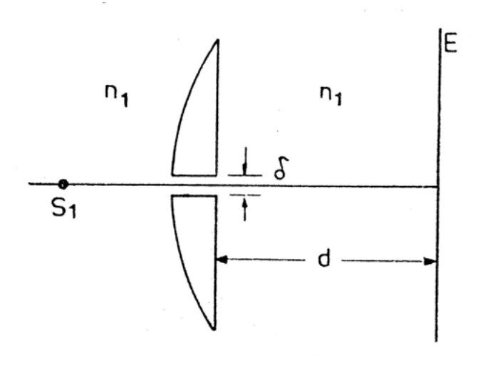
Fig. 4.1
Official English text of the problem.
Answers
-
a) The focal distances and image equation are \[ \boxed{f_1=\frac{R}{n_o-1},\qquad f_2=\frac{n_2R}{n_o-1}}, \qquad \boxed{\frac{f_1}{s_1}+\frac{f_2}{s_2}=1}. \]
-
b) Put \[ f=f_1=\frac{R}{n_o-1},\qquad v=\frac{fs_1}{s_1-f}. \] For the usual screen position, where the outer aperture edges do not limit the interference strip, \[ \boxed{N\simeq N_0 =\frac{\delta^2(s_1+d)} {\lambda\,[d(s_1-f)-fs_1]}}. \] This requires \[ d>v,\qquad r\left(\frac d v-1\right)\ge \delta\left(1+\frac d{s_1}\right). \] Here \(N\) is the usual count obtained by dividing the overlap width by the fringe spacing.
Including finite-aperture clipping, the corresponding count is \[ \boxed{ \overline N= \begin{cases} 0,&d\le v,\\[2mm] \displaystyle \max\!\left\{0,\min\!\left[N_0,\frac{2r\delta}{\lambda f}-N_0\right]\right\}, &d>v. \end{cases}} \] For positive overlap, the integer number of bright maxima, including boundary maxima, is \[ \boxed{N_{\mathrm{bright}} =2\left\lfloor\frac{\overline N}{2}\right\rfloor+1}. \]
Solution
a) Refraction through the two surfaces
Use the thin-lens and Gaussian approximations: neglect the separation of the two surfaces, and retain only first-order terms in ray heights and angles. Take propagation from left to right, with positive \(s_1\) for the real source and positive \(s_2\) for a real image.
Consider a ray incident at height \(y\). Its angle to the optical axis is
\[ \theta_1\simeq\frac{y}{s_1}. \]
Since the centre of curvature is to the right of the convex surface, the surface normal has angle
\[ \nu\simeq-\frac{y}{R}. \]
Let \(\theta_o\) be the ray angle inside the lens. Snell’s law in the small-angle approximation gives
\[ \theta_1-\nu=n_o(\theta_o-\nu), \]
hence
\[ n_o\theta_o =\theta_1-\frac{(n_o-1)y}{R}. \]
At the plane face, whose normal is parallel to the optical axis,
\[ n_2\theta_2=n_o\theta_o. \]
For a ray reaching the axial image,
\[ \theta_2\simeq-\frac{y}{s_2}. \]
Combining these equations and cancelling \(y\) yields
\[ \boxed{\frac1{s_1}+\frac{n_2}{s_2} =\frac{n_o-1}{R}}. \]
The front focal distance is the source distance that makes the outgoing rays parallel. Setting \(s_2\to\infty\),
\[ f_1=\frac{R}{n_o-1}. \]
The rear focal distance is the image distance for parallel incident rays. Setting \(s_1\to\infty\),
\[ f_2=\frac{n_2R}{n_o-1}. \]
Dividing the image equation by \((n_o-1)/R\) therefore gives
\[ \boxed{\frac{f_1}{s_1}+\frac{f_2}{s_2}=1}. \]
The same relation covers virtual images if \(s_2\) is treated as a signed distance.
b) Images formed by the two halves
Both exterior media are now air, so the focal length is
\[ f=\frac{R}{n_o-1}. \]
Each half forms an image at the longitudinal distance \(v\), where
\[ \frac1{s_1}+\frac1v=\frac1f, \qquad v=\frac{fs_1}{s_1-f}>0. \]
Choose the transverse coordinate \(y\) perpendicular to the cut. The full gap shown in the figure is \(\delta\), so the axes of the two halves lie at
\[ c_\pm=\pm\frac{\delta}{2}. \]
Relative to a half-lens axis, the source height is \(-c_\pm\). The transverse magnification is \(-v/s_1\), giving the image positions
\[ y_\pm =c_\pm+\left(-\frac v{s_1}\right)(-c_\pm) =\pm\frac{\delta}{2}\left(1+\frac v{s_1}\right). \]
Consequently, the separation of the two images is
\[ \boxed{b=\delta\left(1+\frac v{s_1}\right) =\frac{\delta v}{f}}. \]
These images act as coherent secondary sources. Reflection symmetry makes their phases equal, so the central fringe is bright.
Fringe spacing
For a screen beyond the image plane, let
\[ L=d-v>0. \]
At screen coordinate \(y\), the paraxial path difference from the two images is
\[ \Delta(y)\simeq\frac{by}{L}. \]
Thus the bright fringes satisfy
\[ y_m=\frac{m\lambda L}{b}, \qquad m\in\mathbb Z, \]
and their spacing is
\[ \boxed{\beta=\frac{\lambda L}{b} =\frac{\lambda f(d-v)}{\delta v}}. \]
They are straight lines parallel to the cut, within the paraxial approximation.
Width of the overlapping beams
We use geometrical beam envelopes and neglect diffraction at the aperture edges.
The ray through the optical centre of each half is undeviated. These two rays reach the screen at
\[ y=\pm H,\qquad H=\frac{\delta}{2}\left(1+\frac d{s_1}\right). \]
Provided the outer aperture edges do not clip the overlap, its width is therefore
\[ W_0=2H=\delta\left(1+\frac d{s_1}\right). \]
Dividing this width by the fringe spacing gives
\[ N_0=\frac{W_0}{\beta} =\frac{\delta^2v}{\lambda f(d-v)} \left(1+\frac d{s_1}\right). \]
Substituting \(v=fs_1/(s_1-f)\),
\[ \boxed{ N_0= \frac{\delta^2(s_1+d)} {\lambda\,[d(s_1-f)-fs_1]} }. \]
For fixed geometry and refractive index, this is proportional to \(1/\lambda\).
Finite-aperture conditions
The statement does not locate the screen relative to the image plane, so the overlap conditions must also be checked.
A ray through height \(y_0\) in the upper half passes through its image at height \(y_+\). Its screen height is
\[ y(d)=\left(1-\frac d v\right)y_0+\frac d v\,y_+. \]
The upper half occupies
\[ \frac{\delta}{2}\le y_0\le\frac{\delta}{2}+r. \]
For \(d>v\), define
\[ \rho=r\left(\frac d v-1\right). \]
On the central section of the screen, the upper beam occupies
\[ H-\rho\le y\le H, \]
and the lower beam occupies
\[ -H\le y\le\rho-H. \]
Their overlap is symmetric about \(y=0\), with width
\[ W= \begin{cases} 0,&\rho\le H,\\ 2(\rho-H),&H<\rho<2H,\\ 2H,&\rho\ge2H. \end{cases} \]
Thus the usual expression \(N_0\) applies when
\[ \rho\ge2H \quad\Longleftrightarrow\quad r\left(\frac d v-1\right) \ge\delta\left(1+\frac d{s_1}\right). \]
In the partially overlapping case,
\[ \frac W\beta =\frac{2\rho}{\beta}-N_0 =\frac{2r\delta}{\lambda f}-N_0. \]
This proves the general expression for \(\overline N=W/\beta\) given in the Answers. For \(d\le v\), the two geometrical beams remain on opposite sides of the symmetry axis and do not overlap.
Finally, when \(W>0\), bright maxima occur at the integers satisfying
\[ |m|\le\frac{W}{2\beta}. \]
Including maxima exactly on the boundary gives
\[ N_{\mathrm{bright}} =2\left\lfloor\frac{W}{2\beta}\right\rfloor+1. \]
The solution was checked against the official solution. Where this solution differs from the official solution, the official solution contains an error or a misprint.
IPhO 1972 · Theorieaufgabe 4
Plankonvexe Linse zwischen zwei Medien; Billetsche geteilte Linse
Eine dünne plankonvexe Linse mit dem Durchmesser \(2r\), dem Krümmungsradius \(R\) und dem Brechungsindex \(n_o\) ist so angeordnet, dass sich auf ihrer linken Seite Luft (\(n_1=1\)) und auf ihrer rechten Seite ein durchsichtiges Medium mit dem Brechungsindex \(n_2\ne 1\) befindet. Die konvexe Fläche der Linse ist der Luft zugewandt. In der Luft befindet sich im Abstand \(s_1\) von der Linse, gemessen entlang der optischen Hauptachse, eine punktförmige Quelle monochromatischen Lichts.
a) Zeigen Sie mithilfe der gaußschen Näherung, dass zwischen der durch den Abstand \(s_2\) von der Linse angegebenen Bildlage und der Lage der Lichtquelle die folgende Beziehung besteht:
\[ \frac{f_1}{s_1}+\frac{f_2}{s_2}=1 \]
wobei \(f_1\) und \(f_2\) die Brennweiten der Linse in Luft beziehungsweise im Medium mit dem Brechungsindex \(n_2\) sind.
Hinweis: Alle Brechungsindizes sind absolute Brechungsindizes.
b) Die Linse wird senkrecht zu ihrer ebenen Fläche in zwei gleiche Teile geschnitten. Diese Teile werden um einen Abstand \(\delta\ll r\) auseinandergerückt (Billetsche Linse). Auf der Symmetrieachse des so entstandenen Systems wird im Abstand \(s_1\) (\(s_1>f_1\)) eine punktförmige Lichtquelle angebracht (Abb. 4.1). Rechts von der Linse befindet sich im Abstand \(d\) ein Schirm E. Der Schirm ist parallel zur ebenen Fläche der Linse. Auf diesem Schirm erscheinen \(N\) Interferenzstreifen, wenn sich rechts von der Linse Luft befindet.
Bestimmen Sie \(N\) in Abhängigkeit von der Wellenlänge.
Abb. 4.1
Aufgabentext aus dem offiziellen englischen Text übersetzt.
Antworten
-
a) Die Brennweiten und die Abbildungsgleichung lauten \[ \boxed{f_1=\frac{R}{n_o-1},\qquad f_2=\frac{n_2R}{n_o-1}}, \qquad \boxed{\frac{f_1}{s_1}+\frac{f_2}{s_2}=1}. \]
-
b) Setzen Sie \[ f=f_1=\frac{R}{n_o-1},\qquad v=\frac{fs_1}{s_1-f}. \] Für die übliche Schirmposition, bei der die äußeren Aperturränder den Interferenzbereich nicht begrenzen, gilt \[ \boxed{N\simeq N_0 =\frac{\delta^2(s_1+d)} {\lambda\,[d(s_1-f)-fs_1]}}. \] Dies setzt voraus, dass \[ d>v,\qquad r\left(\frac d v-1\right)\ge \delta\left(1+\frac d{s_1}\right). \] Dabei ist \(N\) die übliche Anzahl, die sich durch Division der Überlappungsbreite durch den Streifenabstand ergibt.
Unter Berücksichtigung der Beschneidung durch die endliche Apertur lautet die entsprechende Anzahl \[ \boxed{ \overline N= \begin{cases} 0,&d\le v,\\[2mm] \displaystyle \max\!\left\{0,\min\!\left[N_0,\frac{2r\delta}{\lambda f}-N_0\right]\right\}, &d>v. \end{cases}} \] Bei positiver Überlappungsbreite beträgt die ganzzahlige Anzahl heller Maxima einschließlich der Maxima am Rand \[ \boxed{N_{\mathrm{bright}} =2\left\lfloor\frac{\overline N}{2}\right\rfloor+1}. \]
Lösung
a) Brechung an den beiden Flächen
Wir verwenden die Dünnlinsen- und die gaußsche Näherung: Der Abstand zwischen den beiden Flächen wird vernachlässigt, und es werden nur Terme erster Ordnung in den Strahlhöhen und Winkeln berücksichtigt. Die Ausbreitungsrichtung sei von links nach rechts, wobei \(s_1\) für die reelle Quelle und \(s_2\) für ein reelles Bild positiv sind.
Betrachten wir einen Strahl, der in der Höhe \(y\) auftrifft. Sein Winkel zur optischen Achse beträgt
\[ \theta_1\simeq\frac{y}{s_1}. \]
Da der Krümmungsmittelpunkt rechts von der konvexen Fläche liegt, hat die Flächennormale den Winkel
\[ \nu\simeq-\frac{y}{R}. \]
Sei \(\theta_o\) der Strahlwinkel innerhalb der Linse. Das snelliussche Brechungsgesetz ergibt in der Kleinwinkelnäherung
\[ \theta_1-\nu=n_o(\theta_o-\nu), \]
also
\[ n_o\theta_o =\theta_1-\frac{(n_o-1)y}{R}. \]
An der ebenen Fläche, deren Normale parallel zur optischen Achse ist, gilt
\[ n_2\theta_2=n_o\theta_o. \]
Für einen Strahl, der das Bild auf der Achse erreicht, gilt
\[ \theta_2\simeq-\frac{y}{s_2}. \]
Durch Kombination dieser Gleichungen und Kürzen von \(y\) erhält man
\[ \boxed{\frac1{s_1}+\frac{n_2}{s_2} =\frac{n_o-1}{R}}. \]
Die vordere Brennweite ist der Abstand der Quelle, bei dem die austretenden Strahlen parallel sind. Für \(s_2\to\infty\) ergibt sich
\[ f_1=\frac{R}{n_o-1}. \]
Die hintere Brennweite ist die Bildweite bei parallel einfallenden Strahlen. Für \(s_1\to\infty\) ergibt sich
\[ f_2=\frac{n_2R}{n_o-1}. \]
Division der Abbildungsgleichung durch \((n_o-1)/R\) liefert daher
\[ \boxed{\frac{f_1}{s_1}+\frac{f_2}{s_2}=1}. \]
Dieselbe Beziehung gilt auch für virtuelle Bilder, wenn \(s_2\) als vorzeichenbehafteter Abstand behandelt wird.
b) Von den beiden Hälften erzeugte Bilder
Auf beiden Seiten der Linse befindet sich nun Luft, sodass die Brennweite gegeben ist durch
\[ f=\frac{R}{n_o-1}. \]
Jede Hälfte erzeugt ein Bild im Längsabstand \(v\), wobei
\[ \frac1{s_1}+\frac1v=\frac1f, \qquad v=\frac{fs_1}{s_1-f}>0. \]
Wir wählen die Querkoordinate \(y\) senkrecht zum Schnitt. Die gesamte in der Abbildung gezeigte Spaltbreite ist \(\delta\), sodass für die Lage der Achsen der beiden Hälften gilt:
\[ c_\pm=\pm\frac{\delta}{2}. \]
Bezogen auf die Achse einer Linsenhälfte beträgt die Höhe der Quelle \(-c_\pm\). Der laterale Abbildungsmaßstab ist \(-v/s_1\), woraus sich die Bildpositionen ergeben:
\[ y_\pm =c_\pm+\left(-\frac v{s_1}\right)(-c_\pm) =\pm\frac{\delta}{2}\left(1+\frac v{s_1}\right). \]
Folglich beträgt der Abstand zwischen den beiden Bildern
\[ \boxed{b=\delta\left(1+\frac v{s_1}\right) =\frac{\delta v}{f}}. \]
Diese Bilder wirken als kohärente Sekundärquellen. Aufgrund der Spiegelsymmetrie sind ihre Phasen gleich, sodass der zentrale Streifen hell ist.
Streifenabstand
Für einen Schirm hinter der Bildebene setzen wir
\[ L=d-v>0. \]
An der Schirmkoordinate \(y\) beträgt der paraxiale Gangunterschied der von den beiden Bildern ausgehenden Strahlen
\[ \Delta(y)\simeq\frac{by}{L}. \]
Die hellen Streifen erfüllen somit
\[ y_m=\frac{m\lambda L}{b}, \qquad m\in\mathbb Z, \]
und ihr Abstand beträgt
\[ \boxed{\beta=\frac{\lambda L}{b} =\frac{\lambda f(d-v)}{\delta v}}. \]
In der paraxialen Näherung sind sie gerade Linien parallel zum Schnitt.
Breite der überlappenden Strahlenbündel
Wir verwenden geometrische Strahlenbündelbegrenzungen und vernachlässigen die Beugung an den Aperturrändern.
Der Strahl durch das optische Zentrum jeder Hälfte wird nicht abgelenkt. Diese beiden Strahlen erreichen den Schirm bei
\[ y=\pm H,\qquad H=\frac{\delta}{2}\left(1+\frac d{s_1}\right). \]
Sofern die äußeren Aperturränder den Überlappungsbereich nicht beschneiden, beträgt dessen Breite daher
\[ W_0=2H=\delta\left(1+\frac d{s_1}\right). \]
Division dieser Breite durch den Streifenabstand ergibt
\[ N_0=\frac{W_0}{\beta} =\frac{\delta^2v}{\lambda f(d-v)} \left(1+\frac d{s_1}\right). \]
Einsetzen von \(v=fs_1/(s_1-f)\) liefert
\[ \boxed{ N_0= \frac{\delta^2(s_1+d)} {\lambda\,[d(s_1-f)-fs_1]} }. \]
Bei fester Geometrie und festem Brechungsindex ist dies proportional zu \(1/\lambda\).
Bedingungen bei endlicher Apertur
Die Aufgabenstellung legt die Lage des Schirms relativ zur Bildebene nicht fest, sodass auch die Bedingungen für eine Überlappung geprüft werden müssen.
Ein Strahl, der die obere Hälfte in der Höhe \(y_0\) durchläuft, geht durch deren Bild in der Höhe \(y_+\). Seine Höhe auf dem Schirm beträgt
\[ y(d)=\left(1-\frac d v\right)y_0+\frac d v\,y_+. \]
Die obere Hälfte erstreckt sich über
\[ \frac{\delta}{2}\le y_0\le\frac{\delta}{2}+r. \]
Für \(d>v\) definieren wir
\[ \rho=r\left(\frac d v-1\right). \]
Im zentralen Schnitt durch den Schirm erstreckt sich das obere Strahlenbündel über
\[ H-\rho\le y\le H, \]
und das untere Strahlenbündel über
\[ -H\le y\le\rho-H. \]
Ihr Überlappungsbereich ist symmetrisch zu \(y=0\) und hat die Breite
\[ W= \begin{cases} 0,&\rho\le H,\\ 2(\rho-H),&H<\rho<2H,\\ 2H,&\rho\ge2H. \end{cases} \]
Der übliche Ausdruck \(N_0\) gilt somit, wenn
\[ \rho\ge2H \quad\Longleftrightarrow\quad r\left(\frac d v-1\right) \ge\delta\left(1+\frac d{s_1}\right). \]
Im Fall einer teilweisen Überlappung gilt
\[ \frac W\beta =\frac{2\rho}{\beta}-N_0 =\frac{2r\delta}{\lambda f}-N_0. \]
Damit ist der unter Antworten angegebene allgemeine Ausdruck für \(\overline N=W/\beta\) bewiesen. Für \(d\le v\) bleiben die beiden geometrischen Strahlenbündel auf entgegengesetzten Seiten der Symmetrieachse und überlappen sich nicht.
Schließlich treten für \(W>0\) helle Maxima bei den ganzzahligen Werten auf, die folgende Bedingung erfüllen:
\[ |m|\le\frac{W}{2\beta}. \]
Unter Einbeziehung der Maxima genau auf dem Rand ergibt sich
\[ N_{\mathrm{bright}} =2\left\lfloor\frac{W}{2\beta}\right\rfloor+1. \]
Die Lösung wurde mit der offiziellen Lösung abgeglichen. Wo diese Lösung von der offiziellen Lösung abweicht, enthält die offizielle Lösung einen Fehler oder Druckfehler.
IPhO 1972 · Teori sorusu 4
İki ortam arasındaki düzlem-dışbükey mercek; Billet yarık merceği
Çapı \(2r\), eğrilik yarıçapı \(R\) ve kırılma indisi \(n_o\) olan ince bir düzlem-dışbükey mercek, sol tarafında hava (\(n_1=1\)), sağ tarafında ise kırılma indisi \(n_2\ne 1\) olan saydam bir ortam bulunacak şekilde yerleştirilmiştir. Merceğin dışbükey yüzü havaya dönüktür. Havada, asal optik eksen üzerinde ölçüldüğünde mercekten \(s_1\) uzaklıkta, tek renkli ışık yayan noktasal bir kaynak bulunmaktadır.
a) Gauss yaklaşımını kullanarak, mercekten \(s_2\) uzaklığıyla verilen görüntü konumu ile ışık kaynağının konumu arasında şu bağıntının bulunduğunu gösteriniz:
\[ \frac{f_1}{s_1}+\frac{f_2}{s_2}=1 \]
Burada \(f_1\) ve \(f_2\), merceğin sırasıyla havadaki ve kırılma indisi \(n_2\) olan ortamdaki odak uzaklıklarıdır.
Not: Tüm kırılma indisleri mutlak kırılma indisleridir.
b) Mercek, düzlem yüzüne dik olarak iki eşit parçaya kesilir. Bu parçalar, aralarında \(\delta\ll r\) uzaklığı olacak şekilde birbirinden uzaklaştırılır (Billet merceği). Elde edilen sistemin simetri ekseni üzerine, \(s_1\) uzaklıkta (\(s_1>f_1\)) noktasal bir ışık kaynağı yerleştirilir (Şek. 4.1). Merceğin sağ tarafında, \(d\) uzaklıkta bir E ekranı bulunmaktadır. Ekran, merceğin düzlem yüzüne paraleldir. Merceğin sağ tarafında hava bulunması durumunda bu ekranda \(N\) girişim saçağı oluşmaktadır.
\(N\)'yi dalga boyunun fonksiyonu olarak belirleyiniz.
Şek. 4.1
Soru metni resmi İngilizce metinden çevrilmiştir.
Cevaplar
-
a) Odak uzaklıkları ve görüntü denklemi şöyledir: \[ \boxed{f_1=\frac{R}{n_o-1},\qquad f_2=\frac{n_2R}{n_o-1}}, \qquad \boxed{\frac{f_1}{s_1}+\frac{f_2}{s_2}=1}. \]
-
b) Şu tanımları yapalım: \[ f=f_1=\frac{R}{n_o-1},\qquad v=\frac{fs_1}{s_1-f}. \] Açıklığın dış kenarlarının girişim şeridini sınırlamadığı olağan ekran konumu için, \[ \boxed{N\simeq N_0 =\frac{\delta^2(s_1+d)} {\lambda\,[d(s_1-f)-fs_1]}}. \] Bunun için şu koşullar gereklidir: \[ d>v,\qquad r\left(\frac d v-1\right)\ge \delta\left(1+\frac d{s_1}\right). \] Burada \(N\), örtüşme genişliğinin saçak aralığına bölünmesiyle elde edilen alışılmış sayıdır.
Sonlu açıklığın sınırlayıcı etkisi de hesaba katıldığında, karşılık gelen sayı şöyledir: \[ \boxed{ \overline N= \begin{cases} 0,&d\le v,\\[2mm] \displaystyle \max\!\left\{0,\min\!\left[N_0,\frac{2r\delta}{\lambda f}-N_0\right]\right\}, &d>v. \end{cases}} \] Örtüşme genişliği pozitif olduğunda, sınırdaki maksimumlar da dahil olmak üzere aydınlık maksimumların tam sayı adedi şöyledir: \[ \boxed{N_{\mathrm{bright}} =2\left\lfloor\frac{\overline N}{2}\right\rfloor+1}. \]
Çözüm
a) İki yüzeyde kırılma
İnce mercek ve Gauss yaklaşımlarını kullanalım: iki yüzey arasındaki uzaklığı ihmal edelim ve ışın yükseklikleri ile açılarında yalnızca birinci mertebeden terimleri tutalım. Yayılma yönünü soldan sağa alalım; gerçek kaynak için \(s_1\), gerçek görüntü için \(s_2\) pozitif olsun.
\(y\) yüksekliğinde gelen bir ışını ele alalım. Optik eksenle yaptığı açı şöyledir:
\[ \theta_1\simeq\frac{y}{s_1}. \]
Eğrilik merkezi dışbükey yüzeyin sağında olduğundan, yüzey normalinin açısı şöyledir:
\[ \nu\simeq-\frac{y}{R}. \]
Mercek içindeki ışının açısı \(\theta_o\) olsun. Küçük açı yaklaşımında Snell yasası şu bağıntıyı verir:
\[ \theta_1-\nu=n_o(\theta_o-\nu), \]
Buradan
\[ n_o\theta_o =\theta_1-\frac{(n_o-1)y}{R}. \]
Normali optik eksene paralel olan düzlem yüzde,
\[ n_2\theta_2=n_o\theta_o. \]
Eksen üzerindeki görüntüye ulaşan bir ışın için,
\[ \theta_2\simeq-\frac{y}{s_2}. \]
Bu denklemleri birleştirip \(y\)'yi sadeleştirince şu sonuç elde edilir:
\[ \boxed{\frac1{s_1}+\frac{n_2}{s_2} =\frac{n_o-1}{R}}. \]
Ön odak uzaklığı, çıkan ışınları paralel hâle getiren kaynak uzaklığıdır. \(s_2\to\infty\) alındığında,
\[ f_1=\frac{R}{n_o-1}. \]
Arka odak uzaklığı, paralel gelen ışınlar için görüntü uzaklığıdır. \(s_1\to\infty\) alındığında,
\[ f_2=\frac{n_2R}{n_o-1}. \]
Dolayısıyla görüntü denklemini \((n_o-1)/R\)'ye bölünce şu bağıntı elde edilir:
\[ \boxed{\frac{f_1}{s_1}+\frac{f_2}{s_2}=1}. \]
\(s_2\) işaretli bir uzaklık olarak ele alınırsa aynı bağıntı sanal görüntüleri de kapsar.
b) İki yarının oluşturduğu görüntüler
Artık her iki dış ortam da havadır; dolayısıyla odak uzaklığı şöyledir:
\[ f=\frac{R}{n_o-1}. \]
Her yarı, boyuna doğrultuda \(v\) uzaklığında bir görüntü oluşturur; burada
\[ \frac1{s_1}+\frac1v=\frac1f, \qquad v=\frac{fs_1}{s_1-f}>0. \]
Enine koordinat \(y\)'yi kesime dik seçelim. Şekilde gösterilen aralığın tamamı \(\delta\) olduğundan, iki yarının eksenleri şu konumlardadır:
\[ c_\pm=\pm\frac{\delta}{2}. \]
Bir yarım merceğin eksenine göre kaynak yüksekliği \(-c_\pm\)'dir. Enine büyütme \(-v/s_1\) olduğundan görüntü konumları şöyle bulunur:
\[ y_\pm =c_\pm+\left(-\frac v{s_1}\right)(-c_\pm) =\pm\frac{\delta}{2}\left(1+\frac v{s_1}\right). \]
Sonuç olarak, iki görüntü arasındaki uzaklık şöyledir:
\[ \boxed{b=\delta\left(1+\frac v{s_1}\right) =\frac{\delta v}{f}}. \]
Bu görüntüler eşevreli ikincil kaynaklar gibi davranır. Yansıma simetrisi fazlarının eşit olmasını sağlar; dolayısıyla merkezî saçak aydınlıktır.
Saçak aralığı
Görüntü düzleminin ötesindeki bir ekran için şu tanımı yapalım:
\[ L=d-v>0. \]
Ekranın \(y\) koordinatında, iki görüntüden gelen ışınların paraksiyal yaklaşımdaki yol farkı şöyledir:
\[ \Delta(y)\simeq\frac{by}{L}. \]
Böylece aydınlık saçaklar şu koşulu sağlar:
\[ y_m=\frac{m\lambda L}{b}, \qquad m\in\mathbb Z, \]
ve aralıkları şöyledir:
\[ \boxed{\beta=\frac{\lambda L}{b} =\frac{\lambda f(d-v)}{\delta v}}. \]
Paraksiyal yaklaşımda bunlar kesime paralel doğrulardır.
Örtüşen demetlerin genişliği
Geometrik ışın demeti zarflarını kullanıyor ve açıklık kenarlarındaki kırınımı ihmal ediyoruz.
Her yarının optik merkezinden geçen ışın sapmaz. Bu iki ışın ekrana şu konumlarda ulaşır:
\[ y=\pm H,\qquad H=\frac{\delta}{2}\left(1+\frac d{s_1}\right). \]
Açıklığın dış kenarlarının örtüşmeyi sınırlamaması koşuluyla, örtüşme genişliği dolayısıyla şöyledir:
\[ W_0=2H=\delta\left(1+\frac d{s_1}\right). \]
Bu genişliği saçak aralığına bölünce şu sonuç elde edilir:
\[ N_0=\frac{W_0}{\beta} =\frac{\delta^2v}{\lambda f(d-v)} \left(1+\frac d{s_1}\right). \]
\(v=fs_1/(s_1-f)\) yerine konulduğunda,
\[ \boxed{ N_0= \frac{\delta^2(s_1+d)} {\lambda\,[d(s_1-f)-fs_1]} }. \]
Geometri ve kırılma indisi sabitken bu ifade \(1/\lambda\) ile orantılıdır.
Sonlu açıklık koşulları
Soru metni ekranın görüntü düzlemine göre konumunu belirtmediğinden, örtüşme koşulları da kontrol edilmelidir.
Üst yarıdan \(y_0\) yüksekliğinde geçen bir ışın, bu yarının \(y_+\) yüksekliğindeki görüntüsünden geçer. Ekrandaki yüksekliği şöyledir:
\[ y(d)=\left(1-\frac d v\right)y_0+\frac d v\,y_+. \]
Üst yarı şu aralığı kaplar:
\[ \frac{\delta}{2}\le y_0\le\frac{\delta}{2}+r. \]
\(d>v\) için şu tanımı yapalım:
\[ \rho=r\left(\frac d v-1\right). \]
Ekranın merkezî kesitinde üst demet şu aralığı kaplar:
\[ H-\rho\le y\le H, \]
alt demet ise şu aralığı kaplar:
\[ -H\le y\le\rho-H. \]
Örtüşmeleri \(y=0\)'a göre simetriktir ve genişliği şöyledir:
\[ W= \begin{cases} 0,&\rho\le H,\\ 2(\rho-H),&H<\rho<2H,\\ 2H,&\rho\ge2H. \end{cases} \]
Dolayısıyla alışılmış \(N_0\) ifadesi şu koşulda geçerlidir:
\[ \rho\ge2H \quad\Longleftrightarrow\quad r\left(\frac d v-1\right) \ge\delta\left(1+\frac d{s_1}\right). \]
Kısmi örtüşme durumunda,
\[ \frac W\beta =\frac{2\rho}{\beta}-N_0 =\frac{2r\delta}{\lambda f}-N_0. \]
Bu, Cevaplar bölümünde \(\overline N=W/\beta\) için verilen genel ifadeyi kanıtlar. \(d\le v\) için iki geometrik ışın demeti simetri ekseninin karşıt taraflarında kalır ve örtüşmez.
Son olarak, \(W>0\) olduğunda aydınlık maksimumlar şu koşulu sağlayan tam sayılarda oluşur:
\[ |m|\le\frac{W}{2\beta}. \]
Tam sınır üzerinde bulunan maksimumlar da dahil edildiğinde şu sonuç elde edilir:
\[ N_{\mathrm{bright}} =2\left\lfloor\frac{W}{2\beta}\right\rfloor+1. \]
Çözüm, resmi çözümle karşılaştırılarak kontrol edildi. Bu çözümün resmi çözümden ayrıldığı yerlerde resmi çözümde bir hata ya da baskı hatası vardır.
IPhO 1972 · Problema teórico 4
Lente planoconvexa entre dos medios; lente dividida de Billet
Una lente delgada planoconvexa de diámetro \(2r\), radio de curvatura \(R\) e índice de refracción \(n_o\) está situada de modo que a su izquierda hay aire (\(n_1=1\)) y a su derecha hay un medio transparente de índice de refracción \(n_2\ne 1\). La cara convexa de la lente está orientada hacia el aire. En el aire, a una distancia \(s_1\) de la lente, medida sobre el eje óptico principal, hay una fuente puntual de luz monocromática.
a) Demuestre, utilizando la aproximación de Gauss, que entre la posición de la imagen, dada por la distancia \(s_2\) a la lente, y la posición de la fuente luminosa existe la relación:
\[ \frac{f_1}{s_1}+\frac{f_2}{s_2}=1 \]
donde \(f_1\) y \(f_2\) son las distancias focales de la lente en el aire y en el medio de índice de refracción \(n_2\), respectivamente.
Observación: Todos los índices de refracción son índices absolutos.
b) La lente se corta perpendicularmente a su cara plana en dos partes iguales. Estas partes se separan una distancia \(\delta\ll r\) (lente de Billet). Sobre el eje de simetría del sistema obtenido se coloca una fuente puntual de luz a la distancia \(s_1\) (\(s_1>f_1\)) (fig. 4.1). A la derecha de la lente hay una pantalla E a la distancia \(d\). La pantalla es paralela a la cara plana de la lente. En esta pantalla hay \(N\) franjas de interferencia si a la derecha de la lente hay aire.
Determine \(N\) en función de la longitud de onda.
Fig. 4.1
Enunciado traducido del texto oficial en inglés.
Respuestas
-
a) Las distancias focales y la ecuación de formación de imágenes son \[ \boxed{f_1=\frac{R}{n_o-1},\qquad f_2=\frac{n_2R}{n_o-1}}, \qquad \boxed{\frac{f_1}{s_1}+\frac{f_2}{s_2}=1}. \]
-
b) Sea \[ f=f_1=\frac{R}{n_o-1},\qquad v=\frac{fs_1}{s_1-f}. \] Para la posición habitual de la pantalla, en la que los bordes exteriores de la abertura no limitan la zona de interferencia, \[ \boxed{N\simeq N_0 =\frac{\delta^2(s_1+d)} {\lambda\,[d(s_1-f)-fs_1]}}. \] Esto requiere \[ d>v,\qquad r\left(\frac d v-1\right)\ge \delta\left(1+\frac d{s_1}\right). \] Aquí, \(N\) es el recuento habitual obtenido al dividir la anchura de la zona de superposición por la separación entre franjas.
Si se incluye la limitación debida a la abertura finita, el recuento correspondiente es \[ \boxed{ \overline N= \begin{cases} 0,&d\le v,\\[2mm] \displaystyle \max\!\left\{0,\min\!\left[N_0,\frac{2r\delta}{\lambda f}-N_0\right]\right\}, &d>v. \end{cases}} \] Para una superposición de anchura positiva, el número entero de máximos luminosos, incluidos los máximos en los límites, es \[ \boxed{N_{\mathrm{bright}} =2\left\lfloor\frac{\overline N}{2}\right\rfloor+1}. \]
Solución
a) Refracción en las dos superficies
Utilizamos las aproximaciones de lente delgada y de Gauss: despreciamos la separación entre las dos superficies y conservamos únicamente los términos de primer orden en las alturas y los ángulos de los rayos. Tomamos el sentido de propagación de izquierda a derecha, con \(s_1\) positivo para la fuente real y \(s_2\) positivo para una imagen real.
Consideremos un rayo que incide a una altura \(y\). Su ángulo con el eje óptico es
\[ \theta_1\simeq\frac{y}{s_1}. \]
Como el centro de curvatura está a la derecha de la superficie convexa, la normal a la superficie forma un ángulo
\[ \nu\simeq-\frac{y}{R}. \]
Sea \(\theta_o\) el ángulo del rayo dentro de la lente. La ley de Snell en la aproximación de ángulos pequeños da
\[ \theta_1-\nu=n_o(\theta_o-\nu), \]
de donde
\[ n_o\theta_o =\theta_1-\frac{(n_o-1)y}{R}. \]
En la cara plana, cuya normal es paralela al eje óptico,
\[ n_2\theta_2=n_o\theta_o. \]
Para un rayo que llega a la imagen situada sobre el eje,
\[ \theta_2\simeq-\frac{y}{s_2}. \]
Al combinar estas ecuaciones y cancelar \(y\), se obtiene
\[ \boxed{\frac1{s_1}+\frac{n_2}{s_2} =\frac{n_o-1}{R}}. \]
La distancia focal anterior es la distancia de la fuente que hace que los rayos emergentes sean paralelos. Haciendo \(s_2\to\infty\),
\[ f_1=\frac{R}{n_o-1}. \]
La distancia focal posterior es la distancia de la imagen para rayos incidentes paralelos. Haciendo \(s_1\to\infty\),
\[ f_2=\frac{n_2R}{n_o-1}. \]
Por tanto, al dividir la ecuación de formación de imágenes por \((n_o-1)/R\), se obtiene
\[ \boxed{\frac{f_1}{s_1}+\frac{f_2}{s_2}=1}. \]
La misma relación es válida para imágenes virtuales si \(s_2\) se trata como una distancia con signo.
b) Imágenes formadas por las dos mitades
Ahora ambos medios exteriores son aire, por lo que la distancia focal es
\[ f=\frac{R}{n_o-1}. \]
Cada mitad forma una imagen a la distancia longitudinal \(v\), donde
\[ \frac1{s_1}+\frac1v=\frac1f, \qquad v=\frac{fs_1}{s_1-f}>0. \]
Elegimos la coordenada transversal \(y\) perpendicular al corte. La separación total mostrada en la figura es \(\delta\), por lo que los ejes de las dos mitades se encuentran en
\[ c_\pm=\pm\frac{\delta}{2}. \]
Con respecto al eje de cada semilente, la altura de la fuente es \(-c_\pm\). El aumento transversal es \(-v/s_1\), lo que da las posiciones de las imágenes
\[ y_\pm =c_\pm+\left(-\frac v{s_1}\right)(-c_\pm) =\pm\frac{\delta}{2}\left(1+\frac v{s_1}\right). \]
En consecuencia, la separación entre las dos imágenes es
\[ \boxed{b=\delta\left(1+\frac v{s_1}\right) =\frac{\delta v}{f}}. \]
Estas imágenes actúan como fuentes secundarias coherentes. La simetría de reflexión hace que sus fases sean iguales, por lo que la franja central es luminosa.
Separación entre franjas
Para una pantalla situada más allá del plano de las imágenes, sea
\[ L=d-v>0. \]
En la coordenada \(y\) de la pantalla, la diferencia de caminos desde las dos imágenes en la aproximación paraxial es
\[ \Delta(y)\simeq\frac{by}{L}. \]
Así, las franjas luminosas satisfacen
\[ y_m=\frac{m\lambda L}{b}, \qquad m\in\mathbb Z, \]
y su separación es
\[ \boxed{\beta=\frac{\lambda L}{b} =\frac{\lambda f(d-v)}{\delta v}}. \]
Son líneas rectas paralelas al corte, dentro de la aproximación paraxial.
Anchura de la zona de superposición de los haces
Utilizamos las envolventes geométricas de los haces y despreciamos la difracción en los bordes de la abertura.
El rayo que pasa por el centro óptico de cada mitad no se desvía. Estos dos rayos llegan a la pantalla en
\[ y=\pm H,\qquad H=\frac{\delta}{2}\left(1+\frac d{s_1}\right). \]
Siempre que los bordes exteriores de la abertura no recorten la zona de superposición, su anchura es, por tanto,
\[ W_0=2H=\delta\left(1+\frac d{s_1}\right). \]
Al dividir esta anchura por la separación entre franjas se obtiene
\[ N_0=\frac{W_0}{\beta} =\frac{\delta^2v}{\lambda f(d-v)} \left(1+\frac d{s_1}\right). \]
Sustituyendo \(v=fs_1/(s_1-f)\),
\[ \boxed{ N_0= \frac{\delta^2(s_1+d)} {\lambda\,[d(s_1-f)-fs_1]} }. \]
Para una geometría y un índice de refracción fijos, esta expresión es proporcional a \(1/\lambda\).
Condiciones debidas a la abertura finita
El enunciado no especifica la posición de la pantalla con respecto al plano de las imágenes, por lo que también hay que comprobar las condiciones de superposición.
Un rayo que atraviesa la mitad superior a una altura \(y_0\) pasa por su imagen a la altura \(y_+\). Su altura en la pantalla es
\[ y(d)=\left(1-\frac d v\right)y_0+\frac d v\,y_+. \]
La mitad superior ocupa
\[ \frac{\delta}{2}\le y_0\le\frac{\delta}{2}+r. \]
Para \(d>v\), definimos
\[ \rho=r\left(\frac d v-1\right). \]
En la sección central de la pantalla, el haz superior ocupa
\[ H-\rho\le y\le H, \]
y el haz inferior ocupa
\[ -H\le y\le\rho-H. \]
Su zona de superposición es simétrica respecto a \(y=0\), con una anchura
\[ W= \begin{cases} 0,&\rho\le H,\\ 2(\rho-H),&H<\rho<2H,\\ 2H,&\rho\ge2H. \end{cases} \]
Por tanto, la expresión habitual \(N_0\) se aplica cuando
\[ \rho\ge2H \quad\Longleftrightarrow\quad r\left(\frac d v-1\right) \ge\delta\left(1+\frac d{s_1}\right). \]
En el caso de superposición parcial,
\[ \frac W\beta =\frac{2\rho}{\beta}-N_0 =\frac{2r\delta}{\lambda f}-N_0. \]
Esto demuestra la expresión general de \(\overline N=W/\beta\) dada en las Respuestas. Para \(d\le v\), los dos haces geométricos permanecen en lados opuestos del eje de simetría y no se superponen.
Finalmente, cuando \(W>0\), los máximos luminosos corresponden a los enteros que satisfacen
\[ |m|\le\frac{W}{2\beta}. \]
Al incluir los máximos situados exactamente en el límite, se obtiene
\[ N_{\mathrm{bright}} =2\left\lfloor\frac{W}{2\beta}\right\rfloor+1. \]
La solución se comprobó con la solución oficial. Donde esta solución difiere de la solución oficial, la solución oficial contiene un error o una errata.
IPhO 1972 · 理论题 4
两种介质之间的平凸透镜;比累对切透镜
一块直径为 \(2r\)、曲率半径为 \(R\)、折射率为 \(n_o\) 的平凸薄透镜,其左侧为空气(\(n_1=1\)),右侧为折射率 \(n_2\ne 1\) 的透明介质。透镜的凸面朝向空气。在空气中,沿主光轴距透镜 \(s_1\) 处有一个单色点光源。
a) 利用高斯近似证明:由距透镜的距离 \(s_2\) 表示的像的位置与光源的位置之间存在如下关系:
\[ \frac{f_1}{s_1}+\frac{f_2}{s_2}=1 \]
其中,\(f_1\) 和 \(f_2\) 分别为透镜在空气中和在折射率为 \(n_2\) 的介质中的焦距。
注意:所有折射率均为绝对折射率。
b) 沿垂直于透镜平面的方向将透镜切成相等的两半。将这两半移开,使其间距为 \(\delta\ll r\)(比累对切透镜)。在所得系统的对称轴上,距透镜 \(s_1\)(\(s_1>f_1\))处放置一个点光源(图 4.1)。透镜右侧距透镜 \(d\) 处有一个屏 E。屏与透镜的平面平行。如果透镜右侧为空气,屏上会出现 \(N\) 条干涉条纹。
求 \(N\) 随波长变化的函数关系。
图 4.1
题目译自官方英文原文。
答案
-
a) 焦距和成像公式为 \[ \boxed{f_1=\frac{R}{n_o-1},\qquad f_2=\frac{n_2R}{n_o-1}}, \qquad \boxed{\frac{f_1}{s_1}+\frac{f_2}{s_2}=1}. \]
-
b) 令 \[ f=f_1=\frac{R}{n_o-1},\qquad v=\frac{fs_1}{s_1-f}. \] 对于通常的屏的位置,即孔径外缘不限制干涉区域的情形, \[ \boxed{N\simeq N_0 =\frac{\delta^2(s_1+d)} {\lambda\,[d(s_1-f)-fs_1]}}. \] 这要求 \[ d>v,\qquad r\left(\frac d v-1\right)\ge \delta\left(1+\frac d{s_1}\right). \] 这里,\(N\) 是用重叠区域的宽度除以条纹间距得到的通常意义下的条纹数。
考虑有限孔径的截光作用时,相应的条纹数为 \[ \boxed{ \overline N= \begin{cases} 0,&d\le v,\\[2mm] \displaystyle \max\!\left\{0,\min\!\left[N_0,\frac{2r\delta}{\lambda f}-N_0\right]\right\}, &d>v. \end{cases}} \] 当重叠区域的宽度为正时,计入边界上的极大值,亮纹极大值的整数个数为 \[ \boxed{N_{\mathrm{bright}} =2\left\lfloor\frac{\overline N}{2}\right\rfloor+1}. \]
解答
a) 光在两个表面上的折射
采用薄透镜近似和高斯近似:忽略两个表面之间的距离,并且仅保留光线高度和角度的一阶项。取光从左向右传播,实光源的 \(s_1\) 为正,实像的 \(s_2\) 为正。
考虑一条在高度 \(y\) 处入射的光线。它与光轴的夹角为
\[ \theta_1\simeq\frac{y}{s_1}. \]
由于曲率中心位于凸面的右侧,表面法线与光轴的夹角为
\[ \nu\simeq-\frac{y}{R}. \]
设 \(\theta_o\) 为透镜内部光线与光轴的夹角。在小角度近似下,由斯涅尔定律得
\[ \theta_1-\nu=n_o(\theta_o-\nu), \]
因此
\[ n_o\theta_o =\theta_1-\frac{(n_o-1)y}{R}. \]
在法线平行于光轴的平面处,
\[ n_2\theta_2=n_o\theta_o. \]
对于到达轴上像点的光线,
\[ \theta_2\simeq-\frac{y}{s_2}. \]
联立这些方程并约去 \(y\),得到
\[ \boxed{\frac1{s_1}+\frac{n_2}{s_2} =\frac{n_o-1}{R}}. \]
前焦距是使出射光线平行时的物距。令 \(s_2\to\infty\),得
\[ f_1=\frac{R}{n_o-1}. \]
后焦距是平行光入射时的像距。令 \(s_1\to\infty\),得
\[ f_2=\frac{n_2R}{n_o-1}. \]
因此,将成像公式除以 \((n_o-1)/R\),得到
\[ \boxed{\frac{f_1}{s_1}+\frac{f_2}{s_2}=1}. \]
若将 \(s_2\) 视为带符号的距离,同一关系也适用于虚像。
b) 两半透镜所成的像
现在透镜两侧的介质均为空气,因此焦距为
\[ f=\frac{R}{n_o-1}. \]
每一半透镜都在纵向距离 \(v\) 处成像,其中
\[ \frac1{s_1}+\frac1v=\frac1f, \qquad v=\frac{fs_1}{s_1-f}>0. \]
选取垂直于切口的横向坐标 \(y\)。图中所示的完整间隙宽度为 \(\delta\),因此两半透镜的光轴位于
\[ c_\pm=\pm\frac{\delta}{2}. \]
相对于每一半透镜的光轴,光源的高度为 \(-c_\pm\)。横向放大率为 \(-v/s_1\),由此得到像的位置
\[ y_\pm =c_\pm+\left(-\frac v{s_1}\right)(-c_\pm) =\pm\frac{\delta}{2}\left(1+\frac v{s_1}\right). \]
因此,两个像之间的距离为
\[ \boxed{b=\delta\left(1+\frac v{s_1}\right) =\frac{\delta v}{f}}. \]
这两个像充当相干次级光源。镜面对称性使它们的相位相同,因此中央条纹是亮纹。
条纹间距
对于位于像平面之后的屏,令
\[ L=d-v>0. \]
在屏上坐标为 \(y\) 的位置,来自两个像的光线在近轴近似下的光程差为
\[ \Delta(y)\simeq\frac{by}{L}. \]
因此,亮纹满足
\[ y_m=\frac{m\lambda L}{b}, \qquad m\in\mathbb Z, \]
其间距为
\[ \boxed{\beta=\frac{\lambda L}{b} =\frac{\lambda f(d-v)}{\delta v}}. \]
在近轴近似下,这些条纹是平行于切口的直线。
光束重叠区域的宽度
我们采用光束的几何包络,并忽略孔径边缘的衍射。
通过每一半透镜光心的光线不发生偏折。这两条光线到达屏上的位置为
\[ y=\pm H,\qquad H=\frac{\delta}{2}\left(1+\frac d{s_1}\right). \]
只要孔径外缘不截去重叠区域,其宽度就是
\[ W_0=2H=\delta\left(1+\frac d{s_1}\right). \]
用这一宽度除以条纹间距,得到
\[ N_0=\frac{W_0}{\beta} =\frac{\delta^2v}{\lambda f(d-v)} \left(1+\frac d{s_1}\right). \]
代入 \(v=fs_1/(s_1-f)\),得
\[ \boxed{ N_0= \frac{\delta^2(s_1+d)} {\lambda\,[d(s_1-f)-fs_1]} }. \]
当几何参数和折射率固定时,该式与 \(1/\lambda\) 成正比。
有限孔径条件
题目未说明屏相对于像平面的位置,因此还必须检验重叠条件。
一条通过上半透镜中高度 \(y_0\) 处的光线,会经过高度为 \(y_+\) 的像点。它在屏上的高度为
\[ y(d)=\left(1-\frac d v\right)y_0+\frac d v\,y_+. \]
上半透镜所占的范围为
\[ \frac{\delta}{2}\le y_0\le\frac{\delta}{2}+r. \]
对于 \(d>v\),定义
\[ \rho=r\left(\frac d v-1\right). \]
在屏的中央截线上,上方光束所占的范围为
\[ H-\rho\le y\le H, \]
下方光束所占的范围为
\[ -H\le y\le\rho-H. \]
它们的重叠区域关于 \(y=0\) 对称,宽度为
\[ W= \begin{cases} 0,&\rho\le H,\\ 2(\rho-H),&H<\rho<2H,\\ 2H,&\rho\ge2H. \end{cases} \]
因此,通常的表达式 \(N_0\) 适用的条件是
\[ \rho\ge2H \quad\Longleftrightarrow\quad r\left(\frac d v-1\right) \ge\delta\left(1+\frac d{s_1}\right). \]
在部分重叠的情形下,
\[ \frac W\beta =\frac{2\rho}{\beta}-N_0 =\frac{2r\delta}{\lambda f}-N_0. \]
这就证明了答案中给出的 \(\overline N=W/\beta\) 的一般表达式。对于 \(d\le v\),两束几何光束始终位于对称轴的两侧,互不重叠。
最后,当 \(W>0\) 时,亮纹极大值对应于满足下式的整数:
\[ |m|\le\frac{W}{2\beta}. \]
计入恰好位于边界上的极大值,得到
\[ N_{\mathrm{bright}} =2\left\lfloor\frac{W}{2\beta}\right\rfloor+1. \]
解答已与官方解答核对。本解答与官方解答不同之处,均为官方解答中的错误或印刷错误。
IPhO 1972 · Теоретическая задача 4
Плосковыпуклая линза между двумя средами; разрезная линза Бийе
Тонкая плосковыпуклая линза диаметром \(2r\), с радиусом кривизны \(R\) и показателем преломления \(n_o\) расположена так, что слева от неё находится воздух (\(n_1=1\)), а справа — прозрачная среда с показателем преломления \(n_2\ne 1\). Выпуклая поверхность линзы обращена к воздуху. В воздухе на главной оптической оси на расстоянии \(s_1\) от линзы находится точечный источник монохроматического света.
a) Покажите в приближении Гаусса, что положение изображения, задаваемое расстоянием \(s_2\) от линзы, и положение источника света связаны соотношением:
\[ \frac{f_1}{s_1}+\frac{f_2}{s_2}=1 \]
где \(f_1\) и \(f_2\) — фокусные расстояния линзы в воздухе и в среде с показателем преломления \(n_2\) соответственно.
Примечание: все показатели преломления являются абсолютными.
b) Линзу разрезают на две равные части плоскостью, перпендикулярной её плоской поверхности. Эти части раздвигают на расстояние \(\delta\ll r\) (линза Бийе). На оси симметрии полученной системы на расстоянии \(s_1\) (\(s_1>f_1\)) помещают точечный источник света (рис. 4.1). Справа от линзы на расстоянии \(d\) находится экран E. Экран параллелен плоской поверхности линзы. Если справа от линзы находится воздух, на этом экране наблюдается \(N\) интерференционных полос.
Определите \(N\) в зависимости от длины волны.
Рис. 4.1
Условие переведено с официального английского текста.
Ответы
-
a) Фокусные расстояния и уравнение, определяющее положение изображения, имеют вид \[ \boxed{f_1=\frac{R}{n_o-1},\qquad f_2=\frac{n_2R}{n_o-1}}, \qquad \boxed{\frac{f_1}{s_1}+\frac{f_2}{s_2}=1}. \]
-
b) Положим \[ f=f_1=\frac{R}{n_o-1},\qquad v=\frac{fs_1}{s_1-f}. \] При обычном положении экрана, когда внешние края апертуры не ограничивают область интерференции, \[ \boxed{N\simeq N_0 =\frac{\delta^2(s_1+d)} {\lambda\,[d(s_1-f)-fs_1]}}. \] Для этого необходимо выполнение условий \[ d>v,\qquad r\left(\frac d v-1\right)\ge \delta\left(1+\frac d{s_1}\right). \] Здесь \(N\) — обычная оценка числа полос, получаемая делением ширины области перекрытия на расстояние между соседними полосами.
С учётом ограничения пучков конечной апертурой соответствующее число полос равно \[ \boxed{ \overline N= \begin{cases} 0,&d\le v,\\[2mm] \displaystyle \max\!\left\{0,\min\!\left[N_0,\frac{2r\delta}{\lambda f}-N_0\right]\right\}, &d>v. \end{cases}} \] При положительной ширине области перекрытия целое число светлых максимумов, включая максимумы на границе, равно \[ \boxed{N_{\mathrm{bright}} =2\left\lfloor\frac{\overline N}{2}\right\rfloor+1}. \]
Решение
a) Преломление на двух поверхностях
Используем приближения тонкой линзы и Гаусса: пренебрегаем расстоянием между двумя поверхностями и сохраняем только члены первого порядка по высотам и углам лучей. Считаем, что свет распространяется слева направо, причём \(s_1\) положительно для действительного источника, а \(s_2\) положительно для действительного изображения.
Рассмотрим луч, падающий на линзу на высоте \(y\). Его угол с оптической осью равен
\[ \theta_1\simeq\frac{y}{s_1}. \]
Поскольку центр кривизны находится справа от выпуклой поверхности, нормаль к поверхности составляет с осью угол
\[ \nu\simeq-\frac{y}{R}. \]
Обозначим через \(\theta_o\) угол луча внутри линзы. Закон Снеллиуса в приближении малых углов даёт
\[ \theta_1-\nu=n_o(\theta_o-\nu), \]
откуда
\[ n_o\theta_o =\theta_1-\frac{(n_o-1)y}{R}. \]
На плоской поверхности, нормаль к которой параллельна оптической оси,
\[ n_2\theta_2=n_o\theta_o. \]
Для луча, приходящего в изображение на оси,
\[ \theta_2\simeq-\frac{y}{s_2}. \]
Объединяя эти уравнения и сокращая на \(y\), получаем
\[ \boxed{\frac1{s_1}+\frac{n_2}{s_2} =\frac{n_o-1}{R}}. \]
Переднее фокусное расстояние равно расстоянию до источника, при котором выходящие лучи параллельны. Полагая \(s_2\to\infty\), получаем
\[ f_1=\frac{R}{n_o-1}. \]
Заднее фокусное расстояние равно расстоянию до изображения при параллельных падающих лучах. Полагая \(s_1\to\infty\), получаем
\[ f_2=\frac{n_2R}{n_o-1}. \]
Таким образом, деление уравнения, определяющего положение изображения, на \((n_o-1)/R\) даёт
\[ \boxed{\frac{f_1}{s_1}+\frac{f_2}{s_2}=1}. \]
То же соотношение применимо и к мнимым изображениям, если рассматривать \(s_2\) как расстояние с учётом знака.
b) Изображения, создаваемые двумя половинами
Теперь с обеих сторон линзы находится воздух, поэтому фокусное расстояние равно
\[ f=\frac{R}{n_o-1}. \]
Каждая половина создаёт изображение на продольном расстоянии \(v\), где
\[ \frac1{s_1}+\frac1v=\frac1f, \qquad v=\frac{fs_1}{s_1-f}>0. \]
Выберем поперечную координату \(y\) перпендикулярно разрезу. Полная ширина зазора, показанного на рисунке, равна \(\delta\), поэтому оси двух половин расположены при
\[ c_\pm=\pm\frac{\delta}{2}. \]
Относительно оси каждой половины линзы высота источника равна \(-c_\pm\). Поперечное увеличение равно \(-v/s_1\), что даёт следующие положения изображений:
\[ y_\pm =c_\pm+\left(-\frac v{s_1}\right)(-c_\pm) =\pm\frac{\delta}{2}\left(1+\frac v{s_1}\right). \]
Следовательно, расстояние между двумя изображениями равно
\[ \boxed{b=\delta\left(1+\frac v{s_1}\right) =\frac{\delta v}{f}}. \]
Эти изображения служат когерентными вторичными источниками. В силу зеркальной симметрии их фазы одинаковы, поэтому центральная полоса светлая.
Расстояние между соседними полосами
Для экрана, расположенного за плоскостью изображений, положим
\[ L=d-v>0. \]
В точке экрана с координатой \(y\) разность хода лучей от двух изображений в параксиальном приближении равна
\[ \Delta(y)\simeq\frac{by}{L}. \]
Таким образом, положения светлых полос удовлетворяют соотношению
\[ y_m=\frac{m\lambda L}{b}, \qquad m\in\mathbb Z, \]
а расстояние между соседними полосами равно
\[ \boxed{\beta=\frac{\lambda L}{b} =\frac{\lambda f(d-v)}{\delta v}}. \]
В параксиальном приближении полосы представляют собой прямые, параллельные разрезу.
Ширина области перекрытия пучков
Используем геометрические границы пучков и пренебрегаем дифракцией на краях апертуры.
Луч, проходящий через оптический центр каждой половины, не отклоняется. Эти два луча достигают экрана в точках
\[ y=\pm H,\qquad H=\frac{\delta}{2}\left(1+\frac d{s_1}\right). \]
Поэтому, если внешние края апертуры не ограничивают область перекрытия, её ширина равна
\[ W_0=2H=\delta\left(1+\frac d{s_1}\right). \]
Деление этой ширины на расстояние между соседними полосами даёт
\[ N_0=\frac{W_0}{\beta} =\frac{\delta^2v}{\lambda f(d-v)} \left(1+\frac d{s_1}\right). \]
Подставляя \(v=fs_1/(s_1-f)\), получаем
\[ \boxed{ N_0= \frac{\delta^2(s_1+d)} {\lambda\,[d(s_1-f)-fs_1]} }. \]
При фиксированных геометрии системы и показателе преломления эта величина пропорциональна \(1/\lambda\).
Условия, связанные с конечной апертурой
В условии не указано положение экрана относительно плоскости изображений, поэтому необходимо также проверить условия перекрытия.
Луч, проходящий через верхнюю половину на высоте \(y_0\), проходит через создаваемое ею изображение на высоте \(y_+\). Его высота на экране равна
\[ y(d)=\left(1-\frac d v\right)y_0+\frac d v\,y_+. \]
Верхняя половина занимает область
\[ \frac{\delta}{2}\le y_0\le\frac{\delta}{2}+r. \]
При \(d>v\) введём обозначение
\[ \rho=r\left(\frac d v-1\right). \]
В центральном сечении экрана верхний пучок занимает область
\[ H-\rho\le y\le H, \]
а нижний пучок — область
\[ -H\le y\le\rho-H. \]
Область их перекрытия симметрична относительно \(y=0\) и имеет ширину
\[ W= \begin{cases} 0,&\rho\le H,\\ 2(\rho-H),&H<\rho<2H,\\ 2H,&\rho\ge2H. \end{cases} \]
Таким образом, обычное выражение \(N_0\) применимо при условии
\[ \rho\ge2H \quad\Longleftrightarrow\quad r\left(\frac d v-1\right) \ge\delta\left(1+\frac d{s_1}\right). \]
В случае частичного перекрытия
\[ \frac W\beta =\frac{2\rho}{\beta}-N_0 =\frac{2r\delta}{\lambda f}-N_0. \]
Тем самым доказано общее выражение для \(\overline N=W/\beta\), приведённое в разделе «Ответы». При \(d\le v\) два геометрических пучка остаются по разные стороны от оси симметрии и не перекрываются.
Наконец, при \(W>0\) светлым максимумам соответствуют целые числа, удовлетворяющие условию
\[ |m|\le\frac{W}{2\beta}. \]
С учётом максимумов, лежащих точно на границе, получаем
\[ N_{\mathrm{bright}} =2\left\lfloor\frac{W}{2\beta}\right\rfloor+1. \]
Решение проверено по официальному решению. Там, где это решение расходится с официальным, в официальном решении есть ошибка или опечатка.
IPhO 1972 · مسألة نظرية 4
عدسة مستوية محدبة بين وسطين؛ عدسة بيليه المشطورة
تُوضَع عدسة رقيقة مستوية محدبة، قطرها \(2r\)، ونصف قطر تكورها \(R\)، ومعامل انكسارها \(n_o\)، بحيث يوجد الهواء على يسارها (\(n_1=1\))، ويوجد على يمينها وسط شفاف معامل انكساره \(n_2\ne 1\). يتجه الوجه المحدب للعدسة نحو الهواء. ويوجد في الهواء مصدر نقطي لضوء أحادي اللون، على بُعد \(s_1\) من العدسة، مقيسًا على المحور البصري الرئيسي.
a) أثبت، باستخدام تقريب غاوس، أن موضع الصورة، المحدد ببُعدها \(s_2\) عن العدسة، وموضع المصدر الضوئي يرتبطان بالعلاقة:
\[ \frac{f_1}{s_1}+\frac{f_2}{s_2}=1 \]
حيث \(f_1\) و\(f_2\) هما البُعدان البؤريان للعدسة في الهواء وفي الوسط ذي معامل الانكسار \(n_2\)، على الترتيب.
ملاحظة: جميع معاملات الانكسار هي معاملات انكسار مطلقة.
b) تُقطع العدسة إلى جزأين متساويين بمستوى عمودي على وجهها المستوي. ويُباعَد بين الجزأين بمسافة \(\delta\ll r\) (عدسة بيليه). ويوضع مصدر ضوئي نقطي على محور تناظر المنظومة الناتجة، على بُعد \(s_1\) (\(s_1>f_1\)) (الشكل 4.1). وتوجد على يمين العدسة شاشة E على بُعد \(d\). والشاشة موازية للوجه المستوي للعدسة. تظهر على هذه الشاشة \(N\) من أهداب التداخل إذا كان الوسط على يمين العدسة هو الهواء.
حدّد \(N\) بدلالة الطول الموجي.
الشكل 4.1
نص المسألة مترجم عن النص الإنجليزي الرسمي.
الإجابات
-
a) البُعدان البؤريان ومعادلة تكوّن الصورة هما \[ \boxed{f_1=\frac{R}{n_o-1},\qquad f_2=\frac{n_2R}{n_o-1}}, \qquad \boxed{\frac{f_1}{s_1}+\frac{f_2}{s_2}=1}. \]
-
b) لنضع \[ f=f_1=\frac{R}{n_o-1},\qquad v=\frac{fs_1}{s_1-f}. \] عند الموضع المعتاد للشاشة، حيث لا تحدّ الحواف الخارجية للفتحة من شريط التداخل، \[ \boxed{N\simeq N_0 =\frac{\delta^2(s_1+d)} {\lambda\,[d(s_1-f)-fs_1]}}. \] ويتطلب ذلك \[ d>v,\qquad r\left(\frac d v-1\right)\ge \delta\left(1+\frac d{s_1}\right). \] هنا \(N\) هو العدد المعتاد الذي يُحصل عليه بقسمة عرض منطقة التراكب على المسافة بين الأهداب المتتالية.
وعند أخذ اقتطاع الحزم بسبب محدودية الفتحة في الحسبان، يكون العدد المقابل \[ \boxed{ \overline N= \begin{cases} 0,&d\le v,\\[2mm] \displaystyle \max\!\left\{0,\min\!\left[N_0,\frac{2r\delta}{\lambda f}-N_0\right]\right\}, &d>v. \end{cases}} \] عندما يكون عرض منطقة التراكب موجبًا، يكون العدد الصحيح للقيم العظمى المضيئة، بما فيها القيم العظمى الواقعة على الحدود، \[ \boxed{N_{\mathrm{bright}} =2\left\lfloor\frac{\overline N}{2}\right\rfloor+1}. \]
الحل
a) الانكسار عبر السطحين
نستخدم تقريب العدسة الرقيقة وتقريب غاوس: نهمل المسافة الفاصلة بين السطحين، ونحتفظ فقط بالحدود من الرتبة الأولى في ارتفاعات الأشعة وزواياها. نأخذ اتجاه الانتشار من اليسار إلى اليمين، مع اعتبار \(s_1\) موجبًا للمصدر الحقيقي و\(s_2\) موجبًا للصورة الحقيقية.
لننظر إلى شعاع ساقط على ارتفاع \(y\). زاويته مع المحور البصري هي
\[ \theta_1\simeq\frac{y}{s_1}. \]
بما أن مركز التكور يقع إلى يمين السطح المحدب، فإن زاوية العمود المقام على السطح هي
\[ \nu\simeq-\frac{y}{R}. \]
لتكن \(\theta_o\) زاوية الشعاع داخل العدسة. يعطي قانون سنيل، في تقريب الزوايا الصغيرة،
\[ \theta_1-\nu=n_o(\theta_o-\nu), \]
ومن ثم
\[ n_o\theta_o =\theta_1-\frac{(n_o-1)y}{R}. \]
عند الوجه المستوي، الذي يوازي عموده المقام المحور البصري،
\[ n_2\theta_2=n_o\theta_o. \]
بالنسبة إلى شعاع يصل إلى الصورة الواقعة على المحور،
\[ \theta_2\simeq-\frac{y}{s_2}. \]
بدمج هذه المعادلات واختزال \(y\)، نحصل على
\[ \boxed{\frac1{s_1}+\frac{n_2}{s_2} =\frac{n_o-1}{R}}. \]
البُعد البؤري الأمامي هو بُعد المصدر الذي يجعل الأشعة الخارجة متوازية. بوضع \(s_2\to\infty\)،
\[ f_1=\frac{R}{n_o-1}. \]
البُعد البؤري الخلفي هو بُعد الصورة عندما تكون الأشعة الساقطة متوازية. بوضع \(s_1\to\infty\)،
\[ f_2=\frac{n_2R}{n_o-1}. \]
إذن، بقسمة معادلة تكوّن الصورة على \((n_o-1)/R\)، نحصل على
\[ \boxed{\frac{f_1}{s_1}+\frac{f_2}{s_2}=1}. \]
تشمل العلاقة نفسها الصور الوهمية إذا عومل \(s_2\) بوصفه مسافة ذات إشارة.
b) الصورتان اللتان يكوّنهما النصفان
الوسطان الخارجيان الآن كلاهما هواء، لذا فإن البُعد البؤري هو
\[ f=\frac{R}{n_o-1}. \]
يكوّن كل نصف صورة على بُعد طولي \(v\)، حيث
\[ \frac1{s_1}+\frac1v=\frac1f, \qquad v=\frac{fs_1}{s_1-f}>0. \]
نختار الإحداثي المستعرض \(y\) عموديًا على مستوى القطع. عرض الفجوة الكامل الموضح في الشكل هو \(\delta\)، ولذلك يقع محورا النصفين عند
\[ c_\pm=\pm\frac{\delta}{2}. \]
بالنسبة إلى محور نصف العدسة، يكون ارتفاع المصدر \(-c_\pm\). والتكبير المستعرض هو \(-v/s_1\)، مما يعطي موضعي الصورتين
\[ y_\pm =c_\pm+\left(-\frac v{s_1}\right)(-c_\pm) =\pm\frac{\delta}{2}\left(1+\frac v{s_1}\right). \]
وعليه، فإن المسافة الفاصلة بين الصورتين هي
\[ \boxed{b=\delta\left(1+\frac v{s_1}\right) =\frac{\delta v}{f}}. \]
تعمل هاتان الصورتان بوصفهما مصدرين ثانويين مترابطين. ويجعل التناظر الانعكاسي طوريهما متساويين، ولذلك يكون الهدب المركزي مضيئًا.
المسافة بين الأهداب
بالنسبة إلى شاشة تقع خلف مستوى الصورة، لنضع
\[ L=d-v>0. \]
عند الإحداثي \(y\) على الشاشة، يكون فرق المسار من الصورتين في التقريب المحوري
\[ \Delta(y)\simeq\frac{by}{L}. \]
ومن ثم تحقق الأهداب المضيئة
\[ y_m=\frac{m\lambda L}{b}, \qquad m\in\mathbb Z, \]
وتكون المسافة بينها
\[ \boxed{\beta=\frac{\lambda L}{b} =\frac{\lambda f(d-v)}{\delta v}}. \]
وهي خطوط مستقيمة موازية لمستوى القطع، ضمن التقريب المحوري.
عرض منطقة تراكب الحزمتين
نستخدم الأغلفة الهندسية للحزم ونهمل الحيود عند حواف الفتحة.
لا ينحرف الشعاع المار بالمركز البصري لكل نصف. ويصل هذان الشعاعان إلى الشاشة عند
\[ y=\pm H,\qquad H=\frac{\delta}{2}\left(1+\frac d{s_1}\right). \]
بشرط ألا تقتطع الحواف الخارجية للفتحة جزءًا من منطقة التراكب، يكون عرضها إذن
\[ W_0=2H=\delta\left(1+\frac d{s_1}\right). \]
بقسمة هذا العرض على المسافة بين الأهداب، نحصل على
\[ N_0=\frac{W_0}{\beta} =\frac{\delta^2v}{\lambda f(d-v)} \left(1+\frac d{s_1}\right). \]
بالتعويض بـ \(v=fs_1/(s_1-f)\)،
\[ \boxed{ N_0= \frac{\delta^2(s_1+d)} {\lambda\,[d(s_1-f)-fs_1]} }. \]
عند ثبات الترتيب الهندسي ومعامل الانكسار، تتناسب هذه الكمية مع \(1/\lambda\).
شروط الفتحة المحدودة
لا يحدد نص المسألة موضع الشاشة بالنسبة إلى مستوى الصورة، ولذلك يجب أيضًا التحقق من شروط التراكب.
يمر الشعاع الذي يعبر النصف العلوي عند ارتفاع \(y_0\) بصورته عند ارتفاع \(y_+\). ويكون ارتفاعه على الشاشة
\[ y(d)=\left(1-\frac d v\right)y_0+\frac d v\,y_+. \]
يشغل النصف العلوي المجال
\[ \frac{\delta}{2}\le y_0\le\frac{\delta}{2}+r. \]
عندما يكون \(d>v\)، نعرّف
\[ \rho=r\left(\frac d v-1\right). \]
على المقطع المركزي للشاشة، تشغل الحزمة العلوية المجال
\[ H-\rho\le y\le H, \]
وتشغل الحزمة السفلية المجال
\[ -H\le y\le\rho-H. \]
تتناظر منطقة تراكبهما حول \(y=0\)، ويكون عرضها
\[ W= \begin{cases} 0,&\rho\le H,\\ 2(\rho-H),&H<\rho<2H,\\ 2H,&\rho\ge2H. \end{cases} \]
ومن ثم ينطبق التعبير المعتاد \(N_0\) عندما
\[ \rho\ge2H \quad\Longleftrightarrow\quad r\left(\frac d v-1\right) \ge\delta\left(1+\frac d{s_1}\right). \]
في حالة التراكب الجزئي،
\[ \frac W\beta =\frac{2\rho}{\beta}-N_0 =\frac{2r\delta}{\lambda f}-N_0. \]
وهذا يثبت التعبير العام لـ \(\overline N=W/\beta\) الوارد في الإجابات. عندما يكون \(d\le v\)، تبقى الحزمتان الهندسيتان على جانبين متقابلين من محور التناظر ولا تتراكبان.
أخيرًا، عندما يكون \(W>0\)، تقع القيم العظمى المضيئة عند الأعداد الصحيحة التي تحقق
\[ |m|\le\frac{W}{2\beta}. \]
باحتساب القيم العظمى الواقعة تمامًا على الحدود، نحصل على
\[ N_{\mathrm{bright}} =2\left\lfloor\frac{W}{2\beta}\right\rfloor+1. \]
تمت مراجعة الحل بمقارنته بالحل الرسمي. حيثما يختلف هذا الحل عن الحل الرسمي، يحتوي الحل الرسمي على خطأ أو خطأ مطبعي.