IChO 2019 · Theory problem 2
Hydrogen production by water-splitting
Data:
| Compound | \(\ce{H2(g)}\) | \(\ce{H2O(l)}\) | \(\ce{H2O(g)}\) | \(\ce{O2(g)}\) |
|---|---|---|---|---|
| \(\Delta_\mathrm{f}H^\circ\) (\(\mathrm{kJ\,mol^{-1}}\)) | 0 | −285.8 | −241.8 | 0 |
| \(S_\mathrm{m}^\circ\) (\(\mathrm{J\,mol^{-1}\,K^{-1}}\)) | 130.6 | 69.9 | 188.7 | 205.2 |
Molecular hydrogen (\(\ce{H2}\)) can be used as an alternative to carbon dioxide-emitting fuels. Hence, lowering the cost and the environmental impact of its production is a major challenge. In this field, water-splitting is a promising candidate technology.
2.1 Write down the balanced equation of liquid water splitting reaction using a stoichiometric coefficient of 1 for water.
2.2 Using only the provided thermodynamic data, this justify numerically whether reaction is thermodynamically favorable at 298 K.
Water splitting can be performed electrochemically using two electrodes in an acidic water bath, connected by a generator (Fig. 1). Gas bubbles are formed at both electrodes.
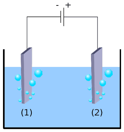
Fig. 1. Water-splitting electrochemical cell.
2.3 Write down the balanced net electrochemical half reactions occurring at each electrode.
2.4 Using only the provided thermodynamic data (or question 2), derive the condition on the applied voltage \(\Delta E_\mathrm{applied}\) between electrodes, compared to value \(\Delta E_\mathrm{th}\) (to determine), for the process to be thermodynamically favorable at 298 K, when all reactants and products are in their standard state. Tick the right condition and give the numerical value with 3 decimal places.
Experimentally, a higher voltage is needed to observe water splitting. For a given \(\ce{Pt}\) cathode, the minimum voltage necessary to observe water splitting, \(\Delta E_\mathrm{min}\), depends on the nature of the anode, as displayed in the table below:
| Anode | \(\Delta E_\mathrm{min}\) (V) |
|---|---|
| \(\ce{IrO_x}\) | 1.6 |
| \(\ce{NiO_x}\) | 1.7 |
| \(\ce{CoO_x}\) | 1.7 |
| \(\ce{Fe2O3}\) | 1.9 |
The difference between \(\Delta E_\mathrm{min}\) and \(\Delta E_\mathrm{th}\) is responsible for losses in the device.
2.5 Give the expression of the device power efficiency \(\eta_\mathrm{elec}\) (fraction of the power used for water splitting) as a function of \(\Delta E_\mathrm{th}\) and \(\Delta E_\mathrm{min}\). Assuming an identical current value \(I\), calculate the water electrolysis power efficiency when a \(\ce{Pt}\) cathode and a \(\ce{Fe2O3}\) anode are used. Give the most efficient anode.
An alternative to water electrolysis is direct photocatalytic water-splitting. It uses a semiconductor that can be activated by absorbing light.
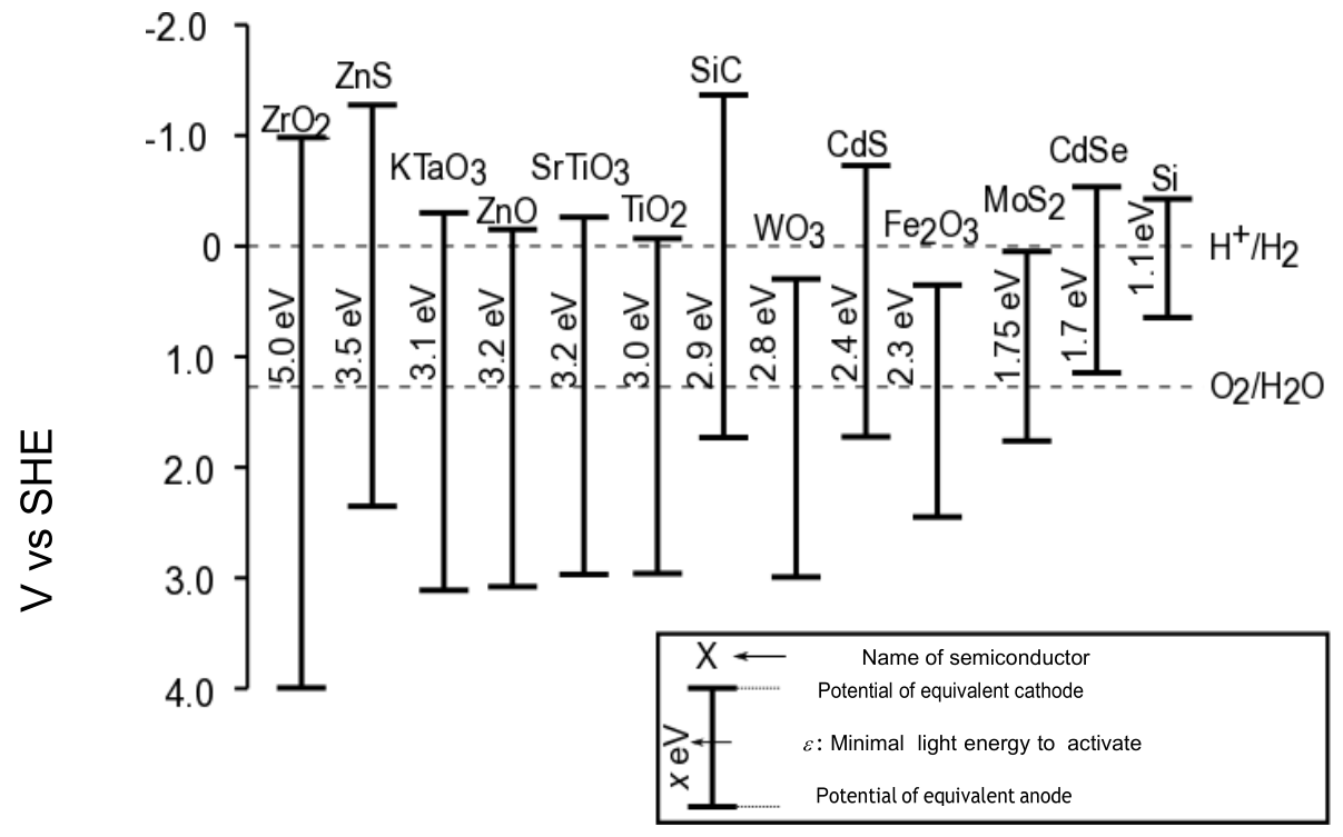
Fig. 2: Activation condition and equivalent electrode potentials of different semiconductors. Dashed lines correspond to water oxidation and reduction potentials. SHE = Standard Hydrogen Electrode
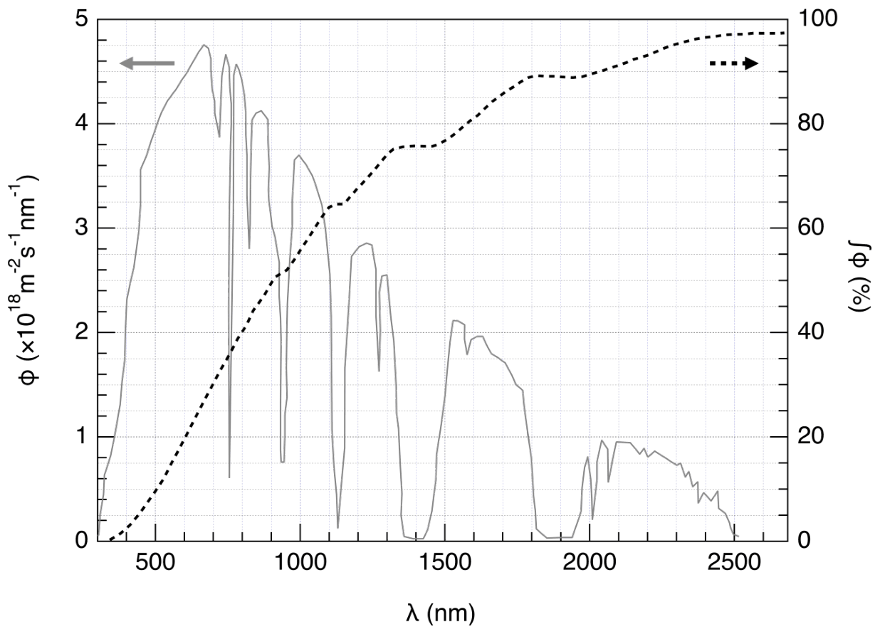
Fig. 3 – Left axis: Spectral distribution of the solar photon flux \(\Phi\). The photon flux is the number of photons per unit area per unit time arriving on the semiconductor. Right axis and dashed line: cumulative photon flux (i.e. fraction of the photon flux with smaller wavelength).
2.6 Estimate the fraction of the solar photon flux that can activate the following semiconductors: \(\ce{TiO2}\), \(\ce{CdS}\), \(\ce{Si}\). State explicitly the equations and units used for the computation.
The activation of the semi-conductor results in a modification of the surface potentials, so that it can be seen as two electrodes of different potentials.
2.7 Using the data in Fig 2, choose the semiconductor(s) in the following list that, once activated, can play both roles of anode and cathode for water-splitting reaction.
2.8 Give the semiconductor that, used as both cathode and anode, is expected to be the most efficient for water splitting upon a given solar shining.
The evolution of \(\ce{H2}\) and \(\ce{O2}\) when a semiconductor is irradiated by simulated solar light at \(T=25\,^\circ\mathrm{C}\) at \(p_\mathrm{atm}\) was recently studied. Using an incident power light of \(P=1.0\,\mathrm{kW\,m^{-2}}\) and a photoelectrode with a \(S=16\,\mathrm{mm^2}\) surface, the production of \(V=0.37\,\mathrm{cm^3}\) of \(\ce{H2(g)}\) was measured after \(\Delta t=1\) hour of reaction.
2.9 Calculate the power efficiency \(\eta_\mathrm{direct}\) of the conversion.
Two modes of converting solar energy to hydrogen can thus be compared: direct photocatalysis, and indirect photo-electrolysis combining a photovoltaic panel with an electrolyzer. The efficiency of photovoltaic panels on the market is around \(\eta_\mathrm{panels}=20\%\).
2.10 Compare the power efficiencies of the two modes, \(\eta_\mathrm{direct}\) and \(\eta_\mathrm{indirect}\), using \(\ce{Fe2O3}\) and \(\ce{Pt}\) electrodes for the electrolysis.
Official English text of the problem.
Answers
Molecular and ionic species used below are water, SMILES O; dihydrogen, SMILES [H][H]; dioxygen, SMILES O=O; and the hydrogen ion (proton), SMILES [H+]. These SMILES do not specify physical phase, aqueous solvation, or the triplet spin state of dioxygen. The electrode and semiconductor materials are extended solids, for which a molecular SMILES does not specify the crystal structure.
-
2.1 \[ \ce{H2O(l) -> H2(g) + 1/2 O2(g)} \]
-
2.2 \(\Delta_\mathrm{r}G^\circ(298\,\mathrm K)=+237.1\,\mathrm{kJ\,mol^{-1}}\). The reaction is not thermodynamically favorable under standard conditions.
-
2.3 Electrode (1) is the negative cathode: \[ \ce{2H+(aq) + 2e- -> H2(g)} \] Electrode (2) is the positive anode: \[ \ce{2H2O(l) -> O2(g) + 4H+(aq) + 4e-} \]
-
2.4 \[ \boxed{\Delta E_\mathrm{applied}>\Delta E_\mathrm{th}, \qquad \Delta E_\mathrm{th}=1.229\,\mathrm V} \] Equality is the reversible limit, with no net thermodynamic driving force.
-
2.5 \[ \boxed{\eta_\mathrm{elec}= \frac{\Delta E_\mathrm{th}}{\Delta E_\mathrm{min}}} \] For \(\ce{Pt}/\ce{Fe2O3}\), \(\eta_\mathrm{elec}\approx64.7\%\). The most efficient anode is iridium oxide, \(\ce{IrO_x}\), giving approximately \(76.8\%\).
-
2.6
| Semiconductor | Maximum activating wavelength | Activating fraction of photon flux |
|---|---|---|
| Titanium dioxide, \(\ce{TiO2}\) | \(413\,\mathrm{nm}\) | approximately \(4\%\) |
| Cadmium sulfide, \(\ce{CdS}\) | \(517\,\mathrm{nm}\) | approximately \(12\%\) |
| Silicon, \(\ce{Si}\) | \(1127\,\mathrm{nm}\) | approximately \(65\%\) |
-
2.7 Among all the materials in Fig. 2, those capable of both half-reactions are \[ \boxed{\ce{ZrO2},\ \ce{ZnS},\ \ce{KTaO3},\ \ce{ZnO},\ \ce{SrTiO3},\ \ce{TiO2},\ \ce{SiC},\ \ce{CdS}}. \]
-
2.8 Cadmium sulfide, \(\ce{CdS}\).
-
2.9 \[ \boxed{\eta_\mathrm{direct}\approx6.2\%} \] using \(p_\mathrm{atm}=1\,\mathrm{atm}\).
-
2.10 \[ \boxed{\eta_\mathrm{indirect} =\eta_\mathrm{panels}\eta_\mathrm{elec} \approx12.9\%} \] The indirect route is approximately 2.1 times as efficient as the measured direct route.
Solution
2.1 — Overall water-splitting reaction
Liquid water forms gaseous hydrogen and oxygen. With the coefficient of water fixed at one, atom balance gives
\[ \boxed{\ce{H2O(l) -> H2(g) + 1/2 O2(g)}}. \]
All molar reaction quantities below refer to this equation: one mole of liquid water consumed and one mole of hydrogen produced.
2.2 — Thermodynamic favorability at 298 K
The standard reaction enthalpy is
\[ \begin{aligned} \Delta_\mathrm{r}H^\circ &=\Delta_\mathrm{f}H^\circ(\ce{H2(g)}) +\frac12\Delta_\mathrm{f}H^\circ(\ce{O2(g)}) -\Delta_\mathrm{f}H^\circ(\ce{H2O(l)})\\ &=0+\frac12(0)-(-285.8)\\ &=+285.8\,\mathrm{kJ\,mol^{-1}}. \end{aligned} \]
The standard reaction entropy is
\[ \begin{aligned} \Delta_\mathrm{r}S^\circ &=130.6+\frac12(205.2)-69.9\\ &=+163.3\,\mathrm{J\,mol^{-1}\,K^{-1}}\\ &=+0.1633\,\mathrm{kJ\,mol^{-1}\,K^{-1}}. \end{aligned} \]
Therefore,
\[ \begin{aligned} \Delta_\mathrm{r}G^\circ &=\Delta_\mathrm{r}H^\circ-T\Delta_\mathrm{r}S^\circ\\ &=285.8-298(0.1633)\\ &=\boxed{+237.1366\,\mathrm{kJ\,mol^{-1}}}. \end{aligned} \]
Since \(\Delta_\mathrm{r}G^\circ>0\), standard-state water splitting is thermodynamically unfavorable at \(298\,\mathrm K\). Energy must be supplied to drive it.
2.3 — Electrode half-reactions
In Fig. 1, electrode (1) is connected to the generator’s negative terminal. It receives electrons and is the cathode, where hydrogen ions are reduced:
\[ \boxed{\ce{2H+(aq) + 2e- -> H2(g)}}. \]
Electrode (2) is connected to the positive terminal. It is the anode, where water is oxidized:
\[ \boxed{\ce{2H2O(l) -> O2(g) + 4H+(aq) + 4e-}}. \]
Multiplying the cathode reaction by two and adding cancels both electrons and hydrogen ions:
\[ \ce{2H2O(l) -> 2H2(g) + O2(g)}. \]
Dividing by two reproduces the equation in 2.1.
2.4 — Thermodynamic threshold voltage
Producing one mole of hydrogen transfers two moles of electrons, corresponding to charge
\[ q=2F, \]
where \(F=96485\,\mathrm{C\,mol^{-1}}\).
The reversible electrical energy required per mole is therefore
\[ 2F\Delta E_\mathrm{th}=\Delta_\mathrm{r}G^\circ. \]
Using \(1\,\mathrm V=1\,\mathrm{J\,C^{-1}}\),
\[ \begin{aligned} \Delta E_\mathrm{th} &=\frac{237136.6\,\mathrm{J\,mol^{-1}}} {2(96485\,\mathrm{C\,mol^{-1}})}\\ &=1.22888\,\mathrm V\\ &=\boxed{1.229\,\mathrm V}. \end{aligned} \]
With an applied voltage supplying electrical work, the net free-energy change per mole is
\[ \Delta G_\mathrm{net} =\Delta_\mathrm{r}G^\circ-2F\Delta E_\mathrm{applied}. \]
For a thermodynamic driving force in the water-splitting direction,
\[ \Delta G_\mathrm{net}<0, \]
so the condition to select is
\[ \boxed{\Delta E_\mathrm{applied}>\Delta E_\mathrm{th}}. \]
At equality, electrolysis is at its reversible threshold.
2.5 — Electrolyzer power efficiency
At current \(I\), the electrical input power at the observed minimum voltage is
\[ P_\mathrm{input}=I\Delta E_\mathrm{min}. \]
The useful power associated with the Gibbs-energy increase of the products is
\[ P_\mathrm{useful}=I\Delta E_\mathrm{th}. \]
Thus,
\[ \boxed{\eta_\mathrm{elec} =\frac{I\Delta E_\mathrm{th}}{I\Delta E_\mathrm{min}} =\frac{\Delta E_\mathrm{th}}{\Delta E_\mathrm{min}}}. \]
For a platinum cathode and iron(III) oxide anode,
\[ \eta_\mathrm{elec} =\frac{1.22888}{1.9} =0.6468 \approx\boxed{64.7\%}. \]
The most efficient anode has the lowest \(\Delta E_\mathrm{min}\). The table gives this as iridium oxide, \(\ce{IrO_x}\):
\[ \eta_\mathrm{elec}(\ce{IrO_x}) =\frac{1.22888}{1.6} =0.7680 \approx\boxed{76.8\%}. \]
2.6 — Fraction of sunlight capable of activation
A photon activates the semiconductor if its energy reaches the minimum activation energy \(\varepsilon\):
\[ E_\gamma=h\nu=\frac{hc}{\lambda}\geq\varepsilon. \]
Hence the activating wavelengths satisfy
\[ \boxed{\lambda\leq\lambda_\mathrm{max}=\frac{hc}{\varepsilon}}. \]
Using
\[ h=6.626\times10^{-34}\,\mathrm{J\,s},\qquad c=2.998\times10^8\,\mathrm{m\,s^{-1}}, \]
and
\[ 1\,\mathrm{eV}=1.602\times10^{-19}\,\mathrm J, \]
the convenient numerical form is
\[ \boxed{\lambda_\mathrm{max}\,[\mathrm{nm}] =\frac{1239.84}{\varepsilon\,[\mathrm{eV}]}}. \]
From Fig. 2:
\[ \begin{aligned} \ce{TiO2}:&\quad \varepsilon=3.0\,\mathrm{eV}, &\lambda_\mathrm{max}&=\frac{1239.84}{3.0}=413\,\mathrm{nm},\\ \ce{CdS}:&\quad \varepsilon=2.4\,\mathrm{eV}, &\lambda_\mathrm{max}&=\frac{1239.84}{2.4}=517\,\mathrm{nm},\\ \ce{Si}:&\quad \varepsilon=1.1\,\mathrm{eV}, &\lambda_\mathrm{max}&=\frac{1239.84}{1.1}=1127\,\mathrm{nm}. \end{aligned} \]
If \(\Phi(\lambda)\) is the spectral photon flux in \(\mathrm{photons\,m^{-2}\,s^{-1}\,nm^{-1}}\), the activating fraction is
\[ f= \frac{\displaystyle\int_0^{\lambda_\mathrm{max}}\Phi(\lambda)\,d\lambda} {\displaystyle\int_0^\infty\Phi(\lambda)\,d\lambda}. \]
Both integrals have units \(\mathrm{photons\,m^{-2}\,s^{-1}}\), so \(f\) is dimensionless. This fraction is given directly by the dashed cumulative curve in Fig. 3.
Reading that curve at the three threshold wavelengths gives approximately
\[ \boxed{ f_{\ce{TiO2}}\approx4\%,\qquad f_{\ce{CdS}}\approx12\%,\qquad f_{\ce{Si}}\approx65\%. } \]
These are fractions of photon flux, rather than fractions of incident radiant power.
2.7 — Semiconductors capable of both half-reactions
For hydrogen evolution, the equivalent cathode must have a potential more negative than the hydrogen-ion/hydrogen couple:
\[ E_\mathrm{cathode} <E^\circ_{\ce{H+}/\ce{H2}} =0\,\mathrm V\quad\text{vs SHE}. \]
For oxygen evolution, the equivalent anode must have a potential more positive than the oxygen/water couple:
\[ E_\mathrm{anode} >E^\circ_{\ce{O2}/\ce{H2O}} \approx+1.229\,\mathrm V\quad\text{vs SHE}. \]
Thus, the semiconductor’s potential interval must span both dashed lines in Fig. 2. Because the numerical potential increases downward in the figure, its upper endpoint must lie above the hydrogen line and its lower endpoint below the oxygen line.
| Materials in Fig. 2 | Hydrogen evolution possible? | Oxygen evolution possible? | Both possible? |
|---|---|---|---|
| \(\ce{ZrO2}\), \(\ce{ZnS}\), \(\ce{KTaO3}\), \(\ce{ZnO}\), \(\ce{SrTiO3}\), \(\ce{TiO2}\), \(\ce{SiC}\), \(\ce{CdS}\) | Yes | Yes | Yes |
| \(\ce{WO3}\), \(\ce{Fe2O3}\), \(\ce{MoS2}\) | No: equivalent cathode potential is too positive | Yes | No |
| \(\ce{CdSe}\), \(\ce{Si}\) | Yes | No: equivalent anode potential is insufficiently positive | No |
The complete qualifying set is therefore zirconium dioxide, zinc sulfide, potassium tantalate, zinc oxide, strontium titanate, titanium dioxide, silicon carbide, and cadmium sulfide.
2.8 — Most efficient semiconductor under the stated model
The semiconductor must first satisfy both potential conditions in 2.7. Among the qualifying materials, cadmium sulfide has the smallest activation energy:
\[ \varepsilon_{\ce{CdS}}=2.4\,\mathrm{eV}. \]
It therefore has the longest activation cutoff wavelength and can use the largest fraction of the incident solar photon flux among those materials. Under the comparison implied by the problem,
\[ \boxed{\text{the expected most efficient semiconductor is }\ce{CdS}.} \]
Although silicon absorbs a larger fraction of solar photons, its equivalent anode potential does not permit water oxidation, so it cannot serve both roles.
2.9 — Direct solar-to-hydrogen efficiency
For consistency with the efficiency definition in 2.5, the useful chemical energy is the Gibbs-energy increase, \(\Delta_\mathrm{r}G^\circ\), per mole of hydrogen produced.
Treat the hydrogen as an ideal gas. Using
\[ p_\mathrm{atm}=101325\,\mathrm{Pa},\qquad T=298.15\,\mathrm K,\qquad R=8.314\,\mathrm{J\,mol^{-1}\,K^{-1}}, \]
and converting the volume,
\[ V=0.37\,\mathrm{cm^3}=3.7\times10^{-7}\,\mathrm{m^3}, \]
gives
\[ \begin{aligned} n(\ce{H2}) &=\frac{p_\mathrm{atm}V}{RT}\\ &=\frac{(101325)(3.7\times10^{-7})} {(8.314)(298.15)}\\ &=1.51\times10^{-5}\,\mathrm{mol}. \end{aligned} \]
The useful chemical energy produced is
\[ \begin{aligned} E_\mathrm{chemical} &=n(\ce{H2})\Delta_\mathrm{r}G^\circ\\ &=(1.512\times10^{-5})(237136.6)\\ &\approx3.59\,\mathrm J. \end{aligned} \]
The incident irradiance, area, and exposure time are
\[ P=1.0\times10^3\,\mathrm{W\,m^{-2}},\qquad S=16\times10^{-6}\,\mathrm{m^2},\qquad \Delta t=3600\,\mathrm s. \]
Therefore,
\[ E_\mathrm{incident}=PS\Delta t =(1.0\times10^3)(16\times10^{-6})(3600) =57.6\,\mathrm J. \]
The ratio of average powers equals the ratio of energies over the same interval:
\[ \begin{aligned} \eta_\mathrm{direct} &=\frac{n(\ce{H2})\Delta_\mathrm{r}G^\circ}{PS\Delta t}\\ &=\frac{3.59}{57.6}\\ &=0.0623. \end{aligned} \]
Thus,
\[ \boxed{\eta_\mathrm{direct}\approx6.2\%}. \]
2.10 — Comparison with photovoltaic-powered electrolysis
The indirect route consists of two successive conversions: sunlight to electricity, then electricity to chemical energy. Its overall efficiency is the product:
\[ \eta_\mathrm{indirect} =\eta_\mathrm{panels}\eta_\mathrm{elec}. \]
For the stated photovoltaic panels and platinum/iron(III) oxide electrolyzer,
\[ \begin{aligned} \eta_\mathrm{indirect} &=0.20\left(\frac{1.22888}{1.9}\right)\\ &=0.1294\\ &\approx\boxed{12.9\%}. \end{aligned} \]
Consequently,
\[ \frac{\eta_\mathrm{indirect}}{\eta_\mathrm{direct}} =\frac{0.1294}{0.0623} \approx2.1. \]
Under the supplied conditions, the indirect route is approximately twice as efficient as the measured direct photocatalytic route.
The solution was checked against the official solution.
IChO 2019 · Theorieaufgabe 2
Wasserstoffgewinnung durch Wasserspaltung
Daten:
| Verbindung | \(\ce{H2(g)}\) | \(\ce{H2O(l)}\) | \(\ce{H2O(g)}\) | \(\ce{O2(g)}\) |
|---|---|---|---|---|
| \(\Delta_\mathrm{f}H^\circ\) (\(\mathrm{kJ\,mol^{-1}}\)) | 0 | −285.8 | −241.8 | 0 |
| \(S_\mathrm{m}^\circ\) (\(\mathrm{J\,mol^{-1}\,K^{-1}}\)) | 130.6 | 69.9 | 188.7 | 205.2 |
Molekularer Wasserstoff (\(\ce{H2}\)) kann als Alternative zu Brennstoffen eingesetzt werden, bei deren Verbrennung Kohlenstoffdioxid freigesetzt wird. Daher ist die Verringerung der Kosten und der Umweltauswirkungen seiner Herstellung eine große Herausforderung. Die Wasserspaltung ist hierfür eine vielversprechende Technologie.
2.1 Stellen Sie die ausgeglichene Reaktionsgleichung für die Spaltung von flüssigem Wasser auf und verwenden Sie dabei für Wasser den stöchiometrischen Koeffizienten 1.
2.2 Begründen Sie anhand einer Rechnung ausschließlich mit den angegebenen thermodynamischen Daten, ob diese Reaktion bei 298 K thermodynamisch begünstigt ist.
Die Wasserspaltung kann elektrochemisch mithilfe von zwei Elektroden in einem sauren Wasserbad durchgeführt werden, die über eine Spannungsquelle miteinander verbunden sind (Abb. 1). An beiden Elektroden entstehen Gasblasen.
Abb. 1. Elektrochemische Zelle zur Wasserspaltung.
2.3 Stellen Sie die ausgeglichenen elektrochemischen Teilreaktionsgleichungen für die an jeder Elektrode ablaufenden Nettoreaktionen auf.
2.4 Leiten Sie ausschließlich mithilfe der angegebenen thermodynamischen Daten (oder von Frage 2) die Bedingung für die zwischen den Elektroden angelegte Spannung \(\Delta E_\mathrm{applied}\) im Vergleich zum (zu bestimmenden) Wert \(\Delta E_\mathrm{th}\) her, damit der Prozess bei 298 K thermodynamisch begünstigt ist, wenn sich alle Edukte und Produkte in ihrem Standardzustand befinden. Kreuzen Sie die richtige Bedingung an und geben Sie den Zahlenwert mit 3 Nachkommastellen an.
Experimentell ist eine höhere Spannung erforderlich, um Wasserspaltung zu beobachten. Für eine gegebene \(\ce{Pt}\)-Kathode hängt die zur Beobachtung der Wasserspaltung erforderliche Mindestspannung \(\Delta E_\mathrm{min}\) vom Anodenmaterial ab, wie die folgende Tabelle zeigt:
| Anode | \(\Delta E_\mathrm{min}\) (V) |
|---|---|
| \(\ce{IrO_x}\) | 1.6 |
| \(\ce{NiO_x}\) | 1.7 |
| \(\ce{CoO_x}\) | 1.7 |
| \(\ce{Fe2O3}\) | 1.9 |
Die Differenz zwischen \(\Delta E_\mathrm{min}\) und \(\Delta E_\mathrm{th}\) ist für Verluste in der Vorrichtung verantwortlich.
2.5 Geben Sie den Ausdruck für den Leistungswirkungsgrad \(\eta_\mathrm{elec}\) der Vorrichtung (den zur Wasserspaltung genutzten Anteil der Leistung) als Funktion von \(\Delta E_\mathrm{th}\) und \(\Delta E_\mathrm{min}\) an. Berechnen Sie unter Annahme einer identischen Stromstärke \(I\) den Leistungswirkungsgrad der Wasserelektrolyse bei Verwendung einer \(\ce{Pt}\)-Kathode und einer \(\ce{Fe2O3}\)-Anode. Geben Sie die effizienteste Anode an.
Eine Alternative zur Wasserelektrolyse ist die direkte photokatalytische Wasserspaltung. Dabei wird ein Halbleiter verwendet, der durch Lichtabsorption aktiviert werden kann.
Abb. 2: Aktivierungsbedingung und äquivalente Elektrodenpotentiale verschiedener Halbleiter. Die gestrichelten Linien entsprechen den Oxidations- und Reduktionspotentialen von Wasser. SHE = Standard-Wasserstoffelektrode
Abb. 3 – Linke Achse: Spektrale Verteilung des solaren Photonenflusses \(\Phi\). Der Photonenfluss ist die Anzahl der Photonen, die pro Flächeneinheit und Zeiteinheit auf dem Halbleiter eintreffen. Rechte Achse und gestrichelte Linie: kumulierter Photonenfluss (d. h. der Anteil des Photonenflusses mit kleinerer Wellenlänge).
2.6 Schätzen Sie den Anteil des solaren Photonenflusses ab, der die folgenden Halbleiter aktivieren kann: \(\ce{TiO2}\), \(\ce{CdS}\), \(\ce{Si}\). Geben Sie die für die Berechnung verwendeten Gleichungen und Einheiten ausdrücklich an.
Die Aktivierung des Halbleiters führt zu einer Änderung der Oberflächenpotentiale, sodass er als zwei Elektroden mit unterschiedlichen Potentialen betrachtet werden kann.
2.7 Wählen Sie anhand der Daten in Abb. 2 aus der folgenden Liste den Halbleiter bzw. die Halbleiter aus, die nach ihrer Aktivierung bei der Wasserspaltungsreaktion sowohl die Rolle der Anode als auch die der Kathode übernehmen können.
2.8 Geben Sie den Halbleiter an, der bei Verwendung sowohl als Kathode als auch als Anode bei einer gegebenen Sonneneinstrahlung voraussichtlich die höchste Effizienz für die Wasserspaltung aufweist.
Kürzlich wurde die Entwicklung von \(\ce{H2}\) und \(\ce{O2}\) bei der Bestrahlung eines Halbleiters mit simuliertem Sonnenlicht bei \(T=25\,^\circ\mathrm{C}\) und \(p_\mathrm{atm}\) untersucht. Bei einer einfallenden Bestrahlungsstärke von \(P=1.0\,\mathrm{kW\,m^{-2}}\) und einer Photoelektrode mit einer Fläche von \(S=16\,\mathrm{mm^2}\) wurde nach einer Reaktionszeit von \(\Delta t=1\) Stunde die Bildung von \(V=0.37\,\mathrm{cm^3}\) \(\ce{H2(g)}\) gemessen.
2.9 Berechnen Sie den Leistungswirkungsgrad \(\eta_\mathrm{direct}\) der Umwandlung.
Somit lassen sich zwei Verfahren zur Umwandlung von Sonnenenergie in Wasserstoff vergleichen: die direkte Photokatalyse und die indirekte Photoelektrolyse, bei der ein Photovoltaikmodul mit einem Elektrolyseur kombiniert wird. Der Wirkungsgrad marktüblicher Photovoltaikmodule liegt bei etwa \(\eta_\mathrm{panels}=20\%\).
2.10 Vergleichen Sie die Leistungswirkungsgrade der beiden Verfahren, \(\eta_\mathrm{direct}\) und \(\eta_\mathrm{indirect}\), bei Verwendung von \(\ce{Fe2O3}\)- und \(\ce{Pt}\)-Elektroden für die Elektrolyse.
Aufgabentext aus dem offiziellen englischen Text übersetzt.
Antworten
Die im Folgenden verwendeten molekularen und ionischen Spezies sind Wasser, SMILES O; molekularer Wasserstoff, SMILES [H][H]; molekularer Sauerstoff, SMILES O=O; und das Wasserstoffion (Proton), SMILES [H+]. Diese SMILES geben weder die physikalische Phase noch die Solvatation in Wasser oder den Triplett-Spinzustand des molekularen Sauerstoffs an. Die Elektroden- und Halbleitermaterialien sind ausgedehnte Festkörper, deren Kristallstruktur durch einen molekularen SMILES nicht beschrieben wird.
-
2.1 \[ \ce{H2O(l) -> H2(g) + 1/2 O2(g)} \]
-
2.2 \(\Delta_\mathrm{r}G^\circ(298\,\mathrm K)=+237.1\,\mathrm{kJ\,mol^{-1}}\). Die Reaktion ist unter Standardbedingungen thermodynamisch nicht begünstigt.
-
2.3 Elektrode (1) ist die negative Kathode: \[ \ce{2H+(aq) + 2e- -> H2(g)} \] Elektrode (2) ist die positive Anode: \[ \ce{2H2O(l) -> O2(g) + 4H+(aq) + 4e-} \]
-
2.4 \[ \boxed{\Delta E_\mathrm{applied}>\Delta E_\mathrm{th}, \qquad \Delta E_\mathrm{th}=1.229\,\mathrm V} \] Die Gleichheit beschreibt den reversiblen Grenzfall ohne resultierende thermodynamische Triebkraft.
-
2.5 \[ \boxed{\eta_\mathrm{elec}= \frac{\Delta E_\mathrm{th}}{\Delta E_\mathrm{min}}} \] Für \(\ce{Pt}/\ce{Fe2O3}\) gilt \(\eta_\mathrm{elec}\approx64.7\%\). Die effizienteste Anode ist Iridiumoxid, \(\ce{IrO_x}\), mit einem Wirkungsgrad von etwa \(76.8\%\).
-
2.6
| Halbleiter | Maximale aktivierende Wellenlänge | Aktivierender Anteil des Photonenflusses |
|---|---|---|
| Titandioxid, \(\ce{TiO2}\) | \(413\,\mathrm{nm}\) | etwa \(4\%\) |
| Cadmiumsulfid, \(\ce{CdS}\) | \(517\,\mathrm{nm}\) | etwa \(12\%\) |
| Silicium, \(\ce{Si}\) | \(1127\,\mathrm{nm}\) | etwa \(65\%\) |
-
2.7 Unter allen Materialien in Abb. 2 sind die folgenden zu beiden Teilreaktionen fähig: \[ \boxed{\ce{ZrO2},\ \ce{ZnS},\ \ce{KTaO3},\ \ce{ZnO},\ \ce{SrTiO3},\ \ce{TiO2},\ \ce{SiC},\ \ce{CdS}}. \]
-
2.8 Cadmiumsulfid, \(\ce{CdS}\).
-
2.9 \[ \boxed{\eta_\mathrm{direct}\approx6.2\%} \] unter Verwendung von \(p_\mathrm{atm}=1\,\mathrm{atm}\).
-
2.10 \[ \boxed{\eta_\mathrm{indirect} =\eta_\mathrm{panels}\eta_\mathrm{elec} \approx12.9\%} \] Das indirekte Verfahren ist etwa 2.1-mal so effizient wie das gemessene direkte Verfahren.
Lösung
2.1 — Gesamtreaktion der Wasserspaltung
Aus flüssigem Wasser entstehen gasförmiger Wasserstoff und Sauerstoff. Wenn der Koeffizient von Wasser auf eins festgelegt wird, ergibt die Atombilanz
\[ \boxed{\ce{H2O(l) -> H2(g) + 1/2 O2(g)}}. \]
Alle folgenden molaren Reaktionsgrößen beziehen sich auf diese Gleichung: Ein Mol flüssiges Wasser wird verbraucht und ein Mol Wasserstoff gebildet.
2.2 — Thermodynamische Begünstigung bei 298 K
Die Standardreaktionsenthalpie beträgt
\[ \begin{aligned} \Delta_\mathrm{r}H^\circ &=\Delta_\mathrm{f}H^\circ(\ce{H2(g)}) +\frac12\Delta_\mathrm{f}H^\circ(\ce{O2(g)}) -\Delta_\mathrm{f}H^\circ(\ce{H2O(l)})\\ &=0+\frac12(0)-(-285.8)\\ &=+285.8\,\mathrm{kJ\,mol^{-1}}. \end{aligned} \]
Die Standardreaktionsentropie beträgt
\[ \begin{aligned} \Delta_\mathrm{r}S^\circ &=130.6+\frac12(205.2)-69.9\\ &=+163.3\,\mathrm{J\,mol^{-1}\,K^{-1}}\\ &=+0.1633\,\mathrm{kJ\,mol^{-1}\,K^{-1}}. \end{aligned} \]
Daher gilt
\[ \begin{aligned} \Delta_\mathrm{r}G^\circ &=\Delta_\mathrm{r}H^\circ-T\Delta_\mathrm{r}S^\circ\\ &=285.8-298(0.1633)\\ &=\boxed{+237.1366\,\mathrm{kJ\,mol^{-1}}}. \end{aligned} \]
Da \(\Delta_\mathrm{r}G^\circ>0\), ist die Wasserspaltung im Standardzustand bei \(298\,\mathrm K\) thermodynamisch nicht begünstigt. Um sie anzutreiben, muss Energie zugeführt werden.
2.3 — Teilreaktionen an den Elektroden
In Abb. 1 ist Elektrode (1) mit dem Minuspol der Spannungsquelle verbunden. Sie nimmt Elektronen auf und ist die Kathode, an der Wasserstoffionen reduziert werden:
\[ \boxed{\ce{2H+(aq) + 2e- -> H2(g)}}. \]
Elektrode (2) ist mit dem Pluspol verbunden. Sie ist die Anode, an der Wasser oxidiert wird:
\[ \boxed{\ce{2H2O(l) -> O2(g) + 4H+(aq) + 4e-}}. \]
Wird die Kathodenreaktion mit zwei multipliziert und zur Anodenreaktion addiert, kürzen sich sowohl die Elektronen als auch die Wasserstoffionen heraus:
\[ \ce{2H2O(l) -> 2H2(g) + O2(g)}. \]
Durch Division durch zwei erhält man wieder die Gleichung aus 2.1.
2.4 — Thermodynamische Schwellenspannung
Bei der Bildung eines Mols Wasserstoff werden zwei Mol Elektronen übertragen; dies entspricht der Ladung
\[ q=2F, \]
wobei \(F=96485\,\mathrm{C\,mol^{-1}}\) gilt.
Die im reversiblen Fall benötigte elektrische Energie pro Mol ist daher
\[ 2F\Delta E_\mathrm{th}=\Delta_\mathrm{r}G^\circ. \]
Mit \(1\,\mathrm V=1\,\mathrm{J\,C^{-1}}\) ergibt sich
\[ \begin{aligned} \Delta E_\mathrm{th} &=\frac{237136.6\,\mathrm{J\,mol^{-1}}} {2(96485\,\mathrm{C\,mol^{-1}})}\\ &=1.22888\,\mathrm V\\ &=\boxed{1.229\,\mathrm V}. \end{aligned} \]
Wenn eine angelegte Spannung elektrische Arbeit zuführt, beträgt die resultierende Änderung der Gibbs-Energie pro Mol
\[ \Delta G_\mathrm{net} =\Delta_\mathrm{r}G^\circ-2F\Delta E_\mathrm{applied}. \]
Für eine thermodynamische Triebkraft in Richtung der Wasserspaltung muss gelten:
\[ \Delta G_\mathrm{net}<0, \]
sodass die auszuwählende Bedingung lautet:
\[ \boxed{\Delta E_\mathrm{applied}>\Delta E_\mathrm{th}}. \]
Bei Gleichheit befindet sich die Elektrolyse an ihrer reversiblen Schwelle.
2.5 — Leistungswirkungsgrad des Elektrolyseurs
Bei der Stromstärke \(I\) beträgt die zugeführte elektrische Leistung bei der beobachteten Mindestspannung
\[ P_\mathrm{input}=I\Delta E_\mathrm{min}. \]
Die mit der Zunahme der Gibbs-Energie der Produkte verbundene Nutzleistung beträgt
\[ P_\mathrm{useful}=I\Delta E_\mathrm{th}. \]
Somit gilt
\[ \boxed{\eta_\mathrm{elec} =\frac{I\Delta E_\mathrm{th}}{I\Delta E_\mathrm{min}} =\frac{\Delta E_\mathrm{th}}{\Delta E_\mathrm{min}}}. \]
Für eine Platinkathode und eine Eisen(III)-oxid-Anode gilt
\[ \eta_\mathrm{elec} =\frac{1.22888}{1.9} =0.6468 \approx\boxed{64.7\%}. \]
Die effizienteste Anode weist den niedrigsten Wert von \(\Delta E_\mathrm{min}\) auf. Laut Tabelle ist dies Iridiumoxid, \(\ce{IrO_x}\):
\[ \eta_\mathrm{elec}(\ce{IrO_x}) =\frac{1.22888}{1.6} =0.7680 \approx\boxed{76.8\%}. \]
2.6 — Zur Aktivierung befähigter Anteil des Sonnenlichts
Ein Photon aktiviert den Halbleiter, wenn seine Energie die minimale Aktivierungsenergie \(\varepsilon\) erreicht:
\[ E_\gamma=h\nu=\frac{hc}{\lambda}\geq\varepsilon. \]
Die aktivierenden Wellenlängen erfüllen daher die Bedingung
\[ \boxed{\lambda\leq\lambda_\mathrm{max}=\frac{hc}{\varepsilon}}. \]
Mit
\[ h=6.626\times10^{-34}\,\mathrm{J\,s},\qquad c=2.998\times10^8\,\mathrm{m\,s^{-1}}, \]
und
\[ 1\,\mathrm{eV}=1.602\times10^{-19}\,\mathrm J, \]
ergibt sich die praktische Zahlenwertgleichung
\[ \boxed{\lambda_\mathrm{max}\,[\mathrm{nm}] =\frac{1239.84}{\varepsilon\,[\mathrm{eV}]}}. \]
Aus Abb. 2 folgt:
\[ \begin{aligned} \ce{TiO2}:&\quad \varepsilon=3.0\,\mathrm{eV}, &\lambda_\mathrm{max}&=\frac{1239.84}{3.0}=413\,\mathrm{nm},\\ \ce{CdS}:&\quad \varepsilon=2.4\,\mathrm{eV}, &\lambda_\mathrm{max}&=\frac{1239.84}{2.4}=517\,\mathrm{nm},\\ \ce{Si}:&\quad \varepsilon=1.1\,\mathrm{eV}, &\lambda_\mathrm{max}&=\frac{1239.84}{1.1}=1127\,\mathrm{nm}. \end{aligned} \]
Wenn \(\Phi(\lambda)\) der spektrale Photonenfluss in \(\mathrm{photons\,m^{-2}\,s^{-1}\,nm^{-1}}\) ist, beträgt der aktivierende Anteil
\[ f= \frac{\displaystyle\int_0^{\lambda_\mathrm{max}}\Phi(\lambda)\,d\lambda} {\displaystyle\int_0^\infty\Phi(\lambda)\,d\lambda}. \]
Beide Integrale haben die Einheit \(\mathrm{photons\,m^{-2}\,s^{-1}}\), sodass \(f\) dimensionslos ist. Dieser Anteil lässt sich direkt aus der gestrichelten kumulativen Kurve in Abb. 3 ablesen.
Das Ablesen dieser Kurve bei den drei Grenzwellenlängen ergibt näherungsweise
\[ \boxed{ f_{\ce{TiO2}}\approx4\%,\qquad f_{\ce{CdS}}\approx12\%,\qquad f_{\ce{Si}}\approx65\%. } \]
Dies sind Anteile des Photonenflusses, nicht Anteile der einfallenden Strahlungsleistung.
2.7 — Halbleiter, die zu beiden Teilreaktionen fähig sind
Für die Wasserstoffentwicklung muss die äquivalente Kathode ein negativeres Potential als das Redoxpaar Wasserstoffion/Wasserstoff aufweisen:
\[ E_\mathrm{cathode} <E^\circ_{\ce{H+}/\ce{H2}} =0\,\mathrm V\quad\text{gegen SHE}. \]
Für die Sauerstoffentwicklung muss die äquivalente Anode ein positiveres Potential als das Redoxpaar Sauerstoff/Wasser aufweisen:
\[ E_\mathrm{anode} >E^\circ_{\ce{O2}/\ce{H2O}} \approx+1.229\,\mathrm V\quad\text{gegen SHE}. \]
Das Potentialintervall des Halbleiters muss somit beide gestrichelten Linien in Abb. 2 überspannen. Da der Zahlenwert des Potentials in der Abbildung nach unten zunimmt, muss sein oberer Endpunkt oberhalb der Wasserstofflinie und sein unterer Endpunkt unterhalb der Sauerstofflinie liegen.
| Materialien in Abb. 2 | Wasserstoffentwicklung möglich? | Sauerstoffentwicklung möglich? | Beides möglich? |
|---|---|---|---|
| \(\ce{ZrO2}\), \(\ce{ZnS}\), \(\ce{KTaO3}\), \(\ce{ZnO}\), \(\ce{SrTiO3}\), \(\ce{TiO2}\), \(\ce{SiC}\), \(\ce{CdS}\) | Ja | Ja | Ja |
| \(\ce{WO3}\), \(\ce{Fe2O3}\), \(\ce{MoS2}\) | Nein: Das äquivalente Kathodenpotential ist zu positiv | Ja | Nein |
| \(\ce{CdSe}\), \(\ce{Si}\) | Ja | Nein: Das äquivalente Anodenpotential ist nicht positiv genug | Nein |
Die vollständige Gruppe geeigneter Materialien besteht daher aus Zirconiumdioxid, Zinksulfid, Kaliumtantalat, Zinkoxid, Strontiumtitanat, Titandioxid, Siliciumcarbid und Cadmiumsulfid.
2.8 — Effizientester Halbleiter im angegebenen Modell
Der Halbleiter muss zunächst beide Potentialbedingungen aus 2.7 erfüllen. Unter den geeigneten Materialien hat Cadmiumsulfid die kleinste Aktivierungsenergie:
\[ \varepsilon_{\ce{CdS}}=2.4\,\mathrm{eV}. \]
Es hat daher die längste Grenzwellenlänge für die Aktivierung und kann unter diesen Materialien den größten Anteil des einfallenden solaren Photonenflusses nutzen. Für den in der Aufgabe zugrunde gelegten Vergleich gilt:
\[ \boxed{\text{der voraussichtlich effizienteste Halbleiter ist }\ce{CdS}.} \]
Obwohl Silicium einen größeren Anteil der solaren Photonen absorbiert, ermöglicht sein äquivalentes Anodenpotential keine Wasseroxidation, sodass es nicht beide Rollen übernehmen kann.
2.9 — Wirkungsgrad der direkten Umwandlung von Sonnenenergie in Wasserstoff
Im Einklang mit der Wirkungsgraddefinition in 2.5 ist die nutzbare chemische Energie die Zunahme der Gibbs-Energie, \(\Delta_\mathrm{r}G^\circ\), pro Mol erzeugten Wasserstoffs.
Der Wasserstoff wird als ideales Gas behandelt. Mit
\[ p_\mathrm{atm}=101325\,\mathrm{Pa},\qquad T=298.15\,\mathrm K,\qquad R=8.314\,\mathrm{J\,mol^{-1}\,K^{-1}}, \]
und nach Umrechnung des Volumens,
\[ V=0.37\,\mathrm{cm^3}=3.7\times10^{-7}\,\mathrm{m^3}, \]
ergibt sich
\[ \begin{aligned} n(\ce{H2}) &=\frac{p_\mathrm{atm}V}{RT}\\ &=\frac{(101325)(3.7\times10^{-7})} {(8.314)(298.15)}\\ &=1.51\times10^{-5}\,\mathrm{mol}. \end{aligned} \]
Die erzeugte nutzbare chemische Energie beträgt
\[ \begin{aligned} E_\mathrm{chemical} &=n(\ce{H2})\Delta_\mathrm{r}G^\circ\\ &=(1.512\times10^{-5})(237136.6)\\ &\approx3.59\,\mathrm J. \end{aligned} \]
Die einfallende Bestrahlungsstärke, die Fläche und die Bestrahlungsdauer betragen
\[ P=1.0\times10^3\,\mathrm{W\,m^{-2}},\qquad S=16\times10^{-6}\,\mathrm{m^2},\qquad \Delta t=3600\,\mathrm s. \]
Daher gilt
\[ E_\mathrm{incident}=PS\Delta t =(1.0\times10^3)(16\times10^{-6})(3600) =57.6\,\mathrm J. \]
Das Verhältnis der mittleren Leistungen ist gleich dem Verhältnis der Energien über dasselbe Zeitintervall:
\[ \begin{aligned} \eta_\mathrm{direct} &=\frac{n(\ce{H2})\Delta_\mathrm{r}G^\circ}{PS\Delta t}\\ &=\frac{3.59}{57.6}\\ &=0.0623. \end{aligned} \]
Somit gilt
\[ \boxed{\eta_\mathrm{direct}\approx6.2\%}. \]
2.10 — Vergleich mit photovoltaisch betriebener Elektrolyse
Das indirekte Verfahren besteht aus zwei aufeinanderfolgenden Umwandlungen: Sonnenlicht wird in elektrische Energie und diese anschließend in chemische Energie umgewandelt. Der Gesamtwirkungsgrad ist das Produkt:
\[ \eta_\mathrm{indirect} =\eta_\mathrm{panels}\eta_\mathrm{elec}. \]
Für die angegebenen Photovoltaikmodule und den Elektrolyseur mit Platin/Eisen(III)-oxid-Elektroden gilt
\[ \begin{aligned} \eta_\mathrm{indirect} &=0.20\left(\frac{1.22888}{1.9}\right)\\ &=0.1294\\ &\approx\boxed{12.9\%}. \end{aligned} \]
Folglich gilt
\[ \frac{\eta_\mathrm{indirect}}{\eta_\mathrm{direct}} =\frac{0.1294}{0.0623} \approx2.1. \]
Unter den angegebenen Bedingungen ist das indirekte Verfahren etwa doppelt so effizient wie das gemessene direkte photokatalytische Verfahren.
Die Lösung wurde mit der offiziellen Lösung abgeglichen.
IChO 2019 · Teori sorusu 2
Suyun ayrıştırılmasıyla hidrojen üretimi
Veriler:
| Bileşik | \(\ce{H2(g)}\) | \(\ce{H2O(l)}\) | \(\ce{H2O(g)}\) | \(\ce{O2(g)}\) |
|---|---|---|---|---|
| \(\Delta_\mathrm{f}H^\circ\) (\(\mathrm{kJ\,mol^{-1}}\)) | 0 | −285.8 | −241.8 | 0 |
| \(S_\mathrm{m}^\circ\) (\(\mathrm{J\,mol^{-1}\,K^{-1}}\)) | 130.6 | 69.9 | 188.7 | 205.2 |
Moleküler hidrojen (\(\ce{H2}\)), karbondioksit salan yakıtlara alternatif olarak kullanılabilir. Bu nedenle, üretiminin maliyetini ve çevresel etkisini azaltmak önemli bir sorundur. Bu alanda suyun ayrıştırılması, umut vadeden bir teknoloji adayıdır.
2.1 Suyun stokiyometrik katsayısını 1 alarak sıvı suyun ayrışma tepkimesinin denkleştirilmiş denklemini yazınız.
2.2 Yalnızca verilen termodinamik verileri kullanarak bu tepkimenin 298 K'de termodinamik açıdan elverişli olup olmadığını sayısal olarak gerekçelendiriniz.
Suyun ayrıştırılması, asidik bir su banyosuna daldırılmış ve bir güç kaynağına bağlanmış iki elektrot kullanılarak elektrokimyasal yolla gerçekleştirilebilir (Şekil 1). Her iki elektrotta da gaz kabarcıkları oluşur.
Şekil 1. Suyun ayrıştırıldığı elektrokimyasal hücre.
2.3 Her bir elektrotta gerçekleşen denkleştirilmiş net elektrokimyasal yarı tepkimeleri yazınız.
2.4 Yalnızca verilen termodinamik verileri (veya 2. soruyu) kullanarak, tüm girenler ve ürünler standart hâllerindeyken işlemin 298 K'de termodinamik açıdan elverişli olması için elektrotlar arasına uygulanan gerilimin, \(\Delta E_\mathrm{applied}\), belirleyeceğiniz \(\Delta E_\mathrm{th}\) değerine göre sağlaması gereken koşulu türetiniz. Doğru koşulu işaretleyiniz ve sayısal değeri virgülden sonra 3 basamakla veriniz.
Deneysel olarak, suyun ayrışmasını gözlemlemek için daha yüksek bir gerilim gerekir. Belirli bir \(\ce{Pt}\) katot için, suyun ayrışmasını gözlemlemek üzere gerekli en düşük gerilim olan \(\Delta E_\mathrm{min}\), aşağıdaki tabloda gösterildiği gibi anodun türüne bağlıdır:
| Anot | \(\Delta E_\mathrm{min}\) (V) |
|---|---|
| \(\ce{IrO_x}\) | 1.6 |
| \(\ce{NiO_x}\) | 1.7 |
| \(\ce{CoO_x}\) | 1.7 |
| \(\ce{Fe2O3}\) | 1.9 |
\(\Delta E_\mathrm{min}\) ile \(\Delta E_\mathrm{th}\) arasındaki fark, cihazdaki kayıplara neden olur.
2.5 Cihazın güç veriminin \(\eta_\mathrm{elec}\) (gücün suyun ayrıştırılmasında kullanılan kısmı), \(\Delta E_\mathrm{th}\) ve \(\Delta E_\mathrm{min}\) cinsinden ifadesini veriniz. Akım değerinin \(I\) aynı olduğunu varsayarak, bir \(\ce{Pt}\) katot ve bir \(\ce{Fe2O3}\) anot kullanıldığında su elektrolizinin güç verimini hesaplayınız. En verimli anodu belirtiniz.
Suyun elektrolizine bir alternatif, suyun doğrudan fotokatalitik olarak ayrıştırılmasıdır. Bu yöntemde ışık soğurarak etkinleşebilen bir yarı iletken kullanılır.
Şekil 2: Farklı yarı iletkenlerin etkinleşme koşulu ve eşdeğer elektrot potansiyelleri. Kesikli çizgiler suyun yükseltgenme ve indirgenme potansiyellerine karşılık gelir. SHE = Standart Hidrojen Elektrodu
Şekil 3 – Sol eksen: Güneş foton akısının \(\Phi\) spektral dağılımı. Foton akısı, yarı iletkenin birim alanına birim zamanda ulaşan foton sayısıdır. Sağ eksen ve kesikli çizgi: kümülatif foton akısı (yani foton akısının daha kısa dalga boyuna sahip kısmı).
2.6 Güneş foton akısının şu yarı iletkenleri etkinleştirebilen kısmını tahmin ediniz: \(\ce{TiO2}\), \(\ce{CdS}\), \(\ce{Si}\). Hesaplamada kullanılan denklemleri ve birimleri açıkça belirtiniz.
Yarı iletkenin etkinleşmesi, yüzey potansiyellerinin değişmesine yol açar; böylece yarı iletken, farklı potansiyellere sahip iki elektrot olarak düşünülebilir.
2.7 Şekil 2'deki verileri kullanarak, etkinleştirildiğinde suyun ayrışma tepkimesi için hem anot hem de katot görevini üstlenebilen yarı iletkeni (veya yarı iletkenleri) aşağıdaki listeden seçiniz.
2.8 Hem katot hem de anot olarak kullanıldığında, belirli bir güneş ışınımı altında suyun ayrıştırılması için en verimli olması beklenen yarı iletkeni belirtiniz.
Bir yarı iletkenin \(T=25\,^\circ\mathrm{C}\) sıcaklıkta ve \(p_\mathrm{atm}\) basıncında benzetilmiş güneş ışığıyla ışınlanması sırasında \(\ce{H2}\) ve \(\ce{O2}\) açığa çıkışı yakın zamanda incelenmiştir. \(P=1.0\,\mathrm{kW\,m^{-2}}\) gelen ışık gücü ve yüzey alanı \(S=16\,\mathrm{mm^2}\) olan bir fotoelektrot kullanılarak, \(\Delta t=1\) saatlik tepkime sonunda \(V=0.37\,\mathrm{cm^3}\) hacminde \(\ce{H2(g)}\) üretildiği ölçülmüştür.
2.9 Dönüşümün güç verimini \(\eta_\mathrm{direct}\) hesaplayınız.
Böylece güneş enerjisini hidrojene dönüştürmenin iki yolu karşılaştırılabilir: doğrudan fotokataliz ve bir fotovoltaik paneli bir elektrolizörle birleştiren dolaylı fotoelektroliz. Piyasadaki fotovoltaik panellerin verimi yaklaşık \(\eta_\mathrm{panels}=20\%\) düzeyindedir.
2.10 Elektrolizde \(\ce{Fe2O3}\) ve \(\ce{Pt}\) elektrotlar kullanıldığında, iki yöntemin güç verimlerini, \(\eta_\mathrm{direct}\) ve \(\eta_\mathrm{indirect}\), karşılaştırınız.
Soru metni resmi İngilizce metinden çevrilmiştir.
Cevaplar
Aşağıda kullanılan moleküler ve iyonik türler su, SMILES O; dihidrojen, SMILES [H][H]; dioksijen, SMILES O=O; ve hidrojen iyonu (proton), SMILES [H+] şeklindedir. Bu SMILES gösterimleri fiziksel fazı, sulu ortamdaki solvatasyonu veya dioksijenin triplet spin hâlini belirtmez. Elektrot ve yarı iletken malzemeleri, kristal yapıları moleküler bir SMILES gösterimiyle belirtilmeyen, uzanımlı katılardır.
-
2.1 \[ \ce{H2O(l) -> H2(g) + 1/2 O2(g)} \]
-
2.2 \(\Delta_\mathrm{r}G^\circ(298\,\mathrm K)=+237.1\,\mathrm{kJ\,mol^{-1}}\). Tepkime standart koşullarda termodinamik açıdan elverişli değildir.
-
2.3 (1) numaralı elektrot negatif katottur: \[ \ce{2H+(aq) + 2e- -> H2(g)} \] (2) numaralı elektrot pozitif anottur: \[ \ce{2H2O(l) -> O2(g) + 4H+(aq) + 4e-} \]
-
2.4 \[ \boxed{\Delta E_\mathrm{applied}>\Delta E_\mathrm{th}, \qquad \Delta E_\mathrm{th}=1.229\,\mathrm V} \] Eşitlik, net termodinamik itici kuvvetin bulunmadığı tersinir sınırdır.
-
2.5 \[ \boxed{\eta_\mathrm{elec}= \frac{\Delta E_\mathrm{th}}{\Delta E_\mathrm{min}}} \] \(\ce{Pt}/\ce{Fe2O3}\) için \(\eta_\mathrm{elec}\approx64.7\%\). En verimli anot, yaklaşık \(76.8\%\) verim sağlayan iridyum oksit, \(\ce{IrO_x}\) anottur.
-
2.6
| Yarı iletken | Etkinleşmeyi sağlayan en büyük dalga boyu | Foton akısının etkinleşmeyi sağlayan kısmı |
|---|---|---|
| Titanyum dioksit, \(\ce{TiO2}\) | \(413\,\mathrm{nm}\) | yaklaşık \(4\%\) |
| Kadmiyum sülfür, \(\ce{CdS}\) | \(517\,\mathrm{nm}\) | yaklaşık \(12\%\) |
| Silisyum, \(\ce{Si}\) | \(1127\,\mathrm{nm}\) | yaklaşık \(65\%\) |
-
2.7 Şekil 2'deki tüm malzemeler arasında her iki yarı tepkimeyi de gerçekleştirebilenler şunlardır: \[ \boxed{\ce{ZrO2},\ \ce{ZnS},\ \ce{KTaO3},\ \ce{ZnO},\ \ce{SrTiO3},\ \ce{TiO2},\ \ce{SiC},\ \ce{CdS}}. \]
-
2.8 Kadmiyum sülfür, \(\ce{CdS}\).
-
2.9 \[ \boxed{\eta_\mathrm{direct}\approx6.2\%} \] \(p_\mathrm{atm}=1\,\mathrm{atm}\) kullanılarak bulunur.
-
2.10 \[ \boxed{\eta_\mathrm{indirect} =\eta_\mathrm{panels}\eta_\mathrm{elec} \approx12.9\%} \] Dolaylı yolun verimi, ölçülen doğrudan yolun veriminin yaklaşık 2.1 katıdır.
Çözüm
2.1 — Suyun toplam ayrışma tepkimesi
Sıvı sudan gaz hâlinde hidrojen ve oksijen oluşur. Suyun katsayısı bir olarak sabitlendiğinde atom denkliği şu sonucu verir:
\[ \boxed{\ce{H2O(l) -> H2(g) + 1/2 O2(g)}}. \]
Aşağıdaki tüm molar tepkime büyüklükleri bu denkleme, yani bir mol sıvı suyun tüketilmesine ve bir mol hidrojenin üretilmesine karşılık gelir.
2.2 — 298 K'de termodinamik elverişlilik
Standart tepkime entalpisi şöyledir:
\[ \begin{aligned} \Delta_\mathrm{r}H^\circ &=\Delta_\mathrm{f}H^\circ(\ce{H2(g)}) +\frac12\Delta_\mathrm{f}H^\circ(\ce{O2(g)}) -\Delta_\mathrm{f}H^\circ(\ce{H2O(l)})\\ &=0+\frac12(0)-(-285.8)\\ &=+285.8\,\mathrm{kJ\,mol^{-1}}. \end{aligned} \]
Standart tepkime entropisi şöyledir:
\[ \begin{aligned} \Delta_\mathrm{r}S^\circ &=130.6+\frac12(205.2)-69.9\\ &=+163.3\,\mathrm{J\,mol^{-1}\,K^{-1}}\\ &=+0.1633\,\mathrm{kJ\,mol^{-1}\,K^{-1}}. \end{aligned} \]
Dolayısıyla,
\[ \begin{aligned} \Delta_\mathrm{r}G^\circ &=\Delta_\mathrm{r}H^\circ-T\Delta_\mathrm{r}S^\circ\\ &=285.8-298(0.1633)\\ &=\boxed{+237.1366\,\mathrm{kJ\,mol^{-1}}}. \end{aligned} \]
\(\Delta_\mathrm{r}G^\circ>0\) olduğundan, standart hâlde suyun ayrıştırılması \(298\,\mathrm K\) sıcaklıkta termodinamik açıdan elverişli değildir. Tepkimeyi gerçekleştirmek için enerji sağlanmalıdır.
2.3 — Elektrot yarı tepkimeleri
Şekil 1'de (1) numaralı elektrot, güç kaynağının negatif kutbuna bağlıdır. Elektron alır ve hidrojen iyonlarının indirgendiği katottur:
\[ \boxed{\ce{2H+(aq) + 2e- -> H2(g)}}. \]
(2) numaralı elektrot pozitif kutba bağlıdır. Suyun yükseltgendiği anottur:
\[ \boxed{\ce{2H2O(l) -> O2(g) + 4H+(aq) + 4e-}}. \]
Katot tepkimesi ikiyle çarpılıp anot tepkimesiyle toplandığında hem elektronlar hem de hidrojen iyonları sadeleşir:
\[ \ce{2H2O(l) -> 2H2(g) + O2(g)}. \]
İkiye bölündüğünde 2.1'deki denklem elde edilir.
2.4 — Termodinamik eşik gerilimi
Bir mol hidrojen üretimi sırasında iki mol elektron aktarılır; buna karşılık gelen yük şöyledir:
\[ q=2F, \]
burada \(F=96485\,\mathrm{C\,mol^{-1}}\) değerindedir.
Dolayısıyla mol başına gereken tersinir elektrik enerjisi şöyledir:
\[ 2F\Delta E_\mathrm{th}=\Delta_\mathrm{r}G^\circ. \]
\(1\,\mathrm V=1\,\mathrm{J\,C^{-1}}\) kullanılarak,
\[ \begin{aligned} \Delta E_\mathrm{th} &=\frac{237136.6\,\mathrm{J\,mol^{-1}}} {2(96485\,\mathrm{C\,mol^{-1}})}\\ &=1.22888\,\mathrm V\\ &=\boxed{1.229\,\mathrm V}. \end{aligned} \]
Uygulanan gerilim elektriksel iş sağladığında, mol başına net serbest enerji değişimi şöyledir:
\[ \Delta G_\mathrm{net} =\Delta_\mathrm{r}G^\circ-2F\Delta E_\mathrm{applied}. \]
Suyun ayrışması yönünde termodinamik bir itici kuvvet bulunması için,
\[ \Delta G_\mathrm{net}<0, \]
olmalıdır; dolayısıyla seçilmesi gereken koşul şudur:
\[ \boxed{\Delta E_\mathrm{applied}>\Delta E_\mathrm{th}}. \]
Eşitlik durumunda elektroliz tersinir eşiğindedir.
2.5 — Elektrolizörün güç verimi
\(I\) akımında, gözlenen en düşük gerilimdeki elektriksel giriş gücü şöyledir:
\[ P_\mathrm{input}=I\Delta E_\mathrm{min}. \]
Ürünlerin Gibbs enerjisindeki artışla ilişkili yararlı güç şöyledir:
\[ P_\mathrm{useful}=I\Delta E_\mathrm{th}. \]
Böylece,
\[ \boxed{\eta_\mathrm{elec} =\frac{I\Delta E_\mathrm{th}}{I\Delta E_\mathrm{min}} =\frac{\Delta E_\mathrm{th}}{\Delta E_\mathrm{min}}}. \]
Bir platin katot ve demir(III) oksit anot için,
\[ \eta_\mathrm{elec} =\frac{1.22888}{1.9} =0.6468 \approx\boxed{64.7\%}. \]
En verimli anot, en düşük \(\Delta E_\mathrm{min}\) değerine sahip olandır. Tabloya göre bu anot iridyum oksit, \(\ce{IrO_x}\), anottur:
\[ \eta_\mathrm{elec}(\ce{IrO_x}) =\frac{1.22888}{1.6} =0.7680 \approx\boxed{76.8\%}. \]
2.6 — Güneş ışığının etkinleşmeyi sağlayabilen kısmı
Bir fotonun enerjisi en düşük etkinleşme enerjisine, \(\varepsilon\), ulaşırsa foton yarı iletkeni etkinleştirir:
\[ E_\gamma=h\nu=\frac{hc}{\lambda}\geq\varepsilon. \]
Bu nedenle etkinleşmeyi sağlayan dalga boyları şu koşulu sağlar:
\[ \boxed{\lambda\leq\lambda_\mathrm{max}=\frac{hc}{\varepsilon}}. \]
Şu değerler:
\[ h=6.626\times10^{-34}\,\mathrm{J\,s},\qquad c=2.998\times10^8\,\mathrm{m\,s^{-1}}, \]
ve
\[ 1\,\mathrm{eV}=1.602\times10^{-19}\,\mathrm J, \]
kullanıldığında, hesaplamaya uygun sayısal biçim şöyledir:
\[ \boxed{\lambda_\mathrm{max}\,[\mathrm{nm}] =\frac{1239.84}{\varepsilon\,[\mathrm{eV}]}}. \]
Şekil 2'den:
\[ \begin{aligned} \ce{TiO2}:&\quad \varepsilon=3.0\,\mathrm{eV}, &\lambda_\mathrm{max}&=\frac{1239.84}{3.0}=413\,\mathrm{nm},\\ \ce{CdS}:&\quad \varepsilon=2.4\,\mathrm{eV}, &\lambda_\mathrm{max}&=\frac{1239.84}{2.4}=517\,\mathrm{nm},\\ \ce{Si}:&\quad \varepsilon=1.1\,\mathrm{eV}, &\lambda_\mathrm{max}&=\frac{1239.84}{1.1}=1127\,\mathrm{nm}. \end{aligned} \]
\(\Phi(\lambda)\), \(\mathrm{photons\,m^{-2}\,s^{-1}\,nm^{-1}}\) biriminde spektral foton akısı ise, etkinleşmeyi sağlayan kısmın oranı şöyledir:
\[ f= \frac{\displaystyle\int_0^{\lambda_\mathrm{max}}\Phi(\lambda)\,d\lambda} {\displaystyle\int_0^\infty\Phi(\lambda)\,d\lambda}. \]
Her iki integralin birimi de \(\mathrm{photons\,m^{-2}\,s^{-1}}\) olduğundan \(f\) boyutsuzdur. Bu oran, Şekil 3'teki kesikli kümülatif eğri tarafından doğrudan verilir.
Bu eğri üç eşik dalga boyunda okunduğunda yaklaşık olarak şu değerler elde edilir:
\[ \boxed{ f_{\ce{TiO2}}\approx4\%,\qquad f_{\ce{CdS}}\approx12\%,\qquad f_{\ce{Si}}\approx65\%. } \]
Bunlar, gelen ışınım gücünün değil, foton akısının oranlarıdır.
2.7 — Her iki yarı tepkimeyi de gerçekleştirebilen yarı iletkenler
Hidrojen açığa çıkması için eşdeğer katodun potansiyeli, hidrojen iyonu/hidrojen çiftinin potansiyelinden daha negatif olmalıdır:
\[ E_\mathrm{cathode} <E^\circ_{\ce{H+}/\ce{H2}} =0\,\mathrm V\quad\text{SHE'ye göre}. \]
Oksijen açığa çıkması için eşdeğer anodun potansiyeli, oksijen/su çiftinin potansiyelinden daha pozitif olmalıdır:
\[ E_\mathrm{anode} >E^\circ_{\ce{O2}/\ce{H2O}} \approx+1.229\,\mathrm V\quad\text{SHE'ye göre}. \]
Dolayısıyla yarı iletkenin potansiyel aralığı, Şekil 2'deki kesikli çizgilerin ikisini de kapsamalıdır. Şekilde potansiyelin sayısal değeri aşağıya doğru arttığı için, aralığın üst ucu hidrojen çizgisinin üstünde, alt ucu ise oksijen çizgisinin altında olmalıdır.
| Şekil 2'deki malzemeler | Hidrojen açığa çıkması mümkün mü? | Oksijen açığa çıkması mümkün mü? | Her ikisi de mümkün mü? |
|---|---|---|---|
| \(\ce{ZrO2}\), \(\ce{ZnS}\), \(\ce{KTaO3}\), \(\ce{ZnO}\), \(\ce{SrTiO3}\), \(\ce{TiO2}\), \(\ce{SiC}\), \(\ce{CdS}\) | Evet | Evet | Evet |
| \(\ce{WO3}\), \(\ce{Fe2O3}\), \(\ce{MoS2}\) | Hayır: eşdeğer katot potansiyeli fazla pozitiftir | Evet | Hayır |
| \(\ce{CdSe}\), \(\ce{Si}\) | Evet | Hayır: eşdeğer anot potansiyeli yeterince pozitif değildir | Hayır |
Dolayısıyla koşulları sağlayan malzemelerin tamamı zirkonyum dioksit, çinko sülfür, potasyum tantalat, çinko oksit, stronsiyum titanat, titanyum dioksit, silisyum karbür ve kadmiyum sülfürdür.
2.8 — Belirtilen modele göre en verimli yarı iletken
Yarı iletken öncelikle 2.7'deki her iki potansiyel koşulunu da sağlamalıdır. Koşulları sağlayan malzemeler arasında en düşük etkinleşme enerjisine kadmiyum sülfür sahiptir:
\[ \varepsilon_{\ce{CdS}}=2.4\,\mathrm{eV}. \]
Bu nedenle bu malzemeler arasında etkinleşme için en uzun sınır dalga boyuna sahiptir ve gelen güneş foton akısının en büyük kısmını kullanabilir. Sorunun öngördüğü karşılaştırmaya göre,
\[ \boxed{\text{en verimli olması beklenen yarı iletken }\ce{CdS}.} \]
Silisyum güneş fotonlarının daha büyük bir kısmını soğursa da eşdeğer anot potansiyeli suyun yükseltgenmesine izin vermediğinden her iki görevi birden üstlenemez.
2.9 — Güneş enerjisinin doğrudan hidrojene dönüştürülmesinin verimi
2.5'teki verim tanımıyla tutarlı olarak, yararlı kimyasal enerji, üretilen hidrojenin molü başına Gibbs enerjisindeki artış, \(\Delta_\mathrm{r}G^\circ\), olarak alınır.
Hidrojeni ideal gaz olarak ele alalım. Şu değerler:
\[ p_\mathrm{atm}=101325\,\mathrm{Pa},\qquad T=298.15\,\mathrm K,\qquad R=8.314\,\mathrm{J\,mol^{-1}\,K^{-1}}, \]
kullanılıp hacim dönüştürüldüğünde,
\[ V=0.37\,\mathrm{cm^3}=3.7\times10^{-7}\,\mathrm{m^3}, \]
şu sonuç elde edilir:
\[ \begin{aligned} n(\ce{H2}) &=\frac{p_\mathrm{atm}V}{RT}\\ &=\frac{(101325)(3.7\times10^{-7})} {(8.314)(298.15)}\\ &=1.51\times10^{-5}\,\mathrm{mol}. \end{aligned} \]
Üretilen yararlı kimyasal enerji şöyledir:
\[ \begin{aligned} E_\mathrm{chemical} &=n(\ce{H2})\Delta_\mathrm{r}G^\circ\\ &=(1.512\times10^{-5})(237136.6)\\ &\approx3.59\,\mathrm J. \end{aligned} \]
Gelen ışınımın güç yoğunluğu, alan ve ışınlama süresi şöyledir:
\[ P=1.0\times10^3\,\mathrm{W\,m^{-2}},\qquad S=16\times10^{-6}\,\mathrm{m^2},\qquad \Delta t=3600\,\mathrm s. \]
Dolayısıyla,
\[ E_\mathrm{incident}=PS\Delta t =(1.0\times10^3)(16\times10^{-6})(3600) =57.6\,\mathrm J. \]
Ortalama güçlerin oranı, aynı zaman aralığındaki enerjilerin oranına eşittir:
\[ \begin{aligned} \eta_\mathrm{direct} &=\frac{n(\ce{H2})\Delta_\mathrm{r}G^\circ}{PS\Delta t}\\ &=\frac{3.59}{57.6}\\ &=0.0623. \end{aligned} \]
Böylece,
\[ \boxed{\eta_\mathrm{direct}\approx6.2\%}. \]
2.10 — Fotovoltaik enerjiyle çalışan elektrolizle karşılaştırma
Dolaylı yol, art arda gerçekleşen iki dönüşümden oluşur: güneş ışığının elektriğe, ardından elektriğin kimyasal enerjiye dönüştürülmesi. Toplam verimi bu iki verimin çarpımıdır:
\[ \eta_\mathrm{indirect} =\eta_\mathrm{panels}\eta_\mathrm{elec}. \]
Belirtilen fotovoltaik paneller ve platin/demir(III) oksit elektrolizörü için,
\[ \begin{aligned} \eta_\mathrm{indirect} &=0.20\left(\frac{1.22888}{1.9}\right)\\ &=0.1294\\ &\approx\boxed{12.9\%}. \end{aligned} \]
Sonuç olarak,
\[ \frac{\eta_\mathrm{indirect}}{\eta_\mathrm{direct}} =\frac{0.1294}{0.0623} \approx2.1. \]
Verilen koşullarda, dolaylı yolun verimi, ölçülen doğrudan fotokatalitik yolun veriminin yaklaşık iki katıdır.
Çözüm, resmi çözümle karşılaştırılarak kontrol edildi.
IChO 2019 · Problema teórico 2
Producción de hidrógeno mediante la descomposición del agua
Datos:
| Compuesto | \(\ce{H2(g)}\) | \(\ce{H2O(l)}\) | \(\ce{H2O(g)}\) | \(\ce{O2(g)}\) |
|---|---|---|---|---|
| \(\Delta_\mathrm{f}H^\circ\) (\(\mathrm{kJ\,mol^{-1}}\)) | 0 | −285.8 | −241.8 | 0 |
| \(S_\mathrm{m}^\circ\) (\(\mathrm{J\,mol^{-1}\,K^{-1}}\)) | 130.6 | 69.9 | 188.7 | 205.2 |
El hidrógeno molecular (\(\ce{H2}\)) puede utilizarse como alternativa a los combustibles que emiten dióxido de carbono. Por ello, reducir el coste y el impacto ambiental de su producción constituye un reto importante. En este ámbito, la descomposición del agua es una tecnología prometedora.
2.1 Escriba la ecuación ajustada de la reacción de descomposición del agua líquida utilizando un coeficiente estequiométrico de 1 para el agua.
2.2 Utilizando únicamente los datos termodinámicos proporcionados, justifique numéricamente si esta reacción es termodinámicamente favorable a 298 K.
La descomposición del agua puede llevarse a cabo electroquímicamente utilizando dos electrodos en un baño acuoso ácido, conectados mediante un generador (Fig. 1). En ambos electrodos se forman burbujas de gas.
Fig. 1. Celda electroquímica para la descomposición del agua.
2.3 Escriba las semirreacciones electroquímicas netas ajustadas que tienen lugar en cada electrodo.
2.4 Utilizando únicamente los datos termodinámicos proporcionados (o la pregunta 2), deduzca la condición que debe cumplir la tensión aplicada \(\Delta E_\mathrm{applied}\) entre los electrodos, en comparación con el valor \(\Delta E_\mathrm{th}\) (que debe determinar), para que el proceso sea termodinámicamente favorable a 298 K cuando todos los reactivos y productos se encuentren en su estado estándar. Marque la condición correcta e indique el valor numérico con 3 decimales.
Experimentalmente, se necesita una tensión mayor para observar la descomposición del agua. Para un cátodo dado de \(\ce{Pt}\), la tensión mínima necesaria para observar la descomposición del agua, \(\Delta E_\mathrm{min}\), depende de la naturaleza del ánodo, como se muestra en la siguiente tabla:
| Ánodo | \(\Delta E_\mathrm{min}\) (V) |
|---|---|
| \(\ce{IrO_x}\) | 1.6 |
| \(\ce{NiO_x}\) | 1.7 |
| \(\ce{CoO_x}\) | 1.7 |
| \(\ce{Fe2O3}\) | 1.9 |
La diferencia entre \(\Delta E_\mathrm{min}\) y \(\Delta E_\mathrm{th}\) es responsable de las pérdidas en el dispositivo.
2.5 Indique la expresión de la eficiencia energética del dispositivo \(\eta_\mathrm{elec}\) (fracción de la potencia utilizada para la descomposición del agua) en función de \(\Delta E_\mathrm{th}\) y \(\Delta E_\mathrm{min}\). Suponiendo un mismo valor de corriente \(I\), calcule la eficiencia energética de la electrólisis del agua cuando se utilizan un cátodo de \(\ce{Pt}\) y un ánodo de \(\ce{Fe2O3}\). Indique cuál es el ánodo más eficiente.
Una alternativa a la electrólisis del agua es la descomposición fotocatalítica directa del agua. Esta utiliza un semiconductor que puede activarse mediante la absorción de luz.
Fig. 2: Condición de activación y potenciales de electrodo equivalentes de distintos semiconductores. Las líneas discontinuas corresponden a los potenciales de oxidación y reducción del agua. SHE = electrodo estándar de hidrógeno
Fig. 3 – Eje izquierdo: Distribución espectral del flujo de fotones solares \(\Phi\). El flujo de fotones es el número de fotones por unidad de superficie y por unidad de tiempo que llegan al semiconductor. Eje derecho y línea discontinua: flujo de fotones acumulado (es decir, fracción del flujo de fotones con una longitud de onda menor).
2.6 Estime la fracción del flujo de fotones solares que puede activar los siguientes semiconductores: \(\ce{TiO2}\), \(\ce{CdS}\), \(\ce{Si}\). Indique explícitamente las ecuaciones y las unidades utilizadas en el cálculo.
La activación del semiconductor provoca una modificación de los potenciales superficiales, de modo que puede considerarse como dos electrodos de distintos potenciales.
2.7 Utilizando los datos de la Fig. 2, elija de la siguiente lista el semiconductor o los semiconductores que, una vez activados, puedan desempeñar tanto la función de ánodo como la de cátodo en la reacción de descomposición del agua.
2.8 Indique el semiconductor que, utilizado tanto como cátodo como ánodo, se espera que sea el más eficiente para la descomposición del agua bajo una irradiación solar dada.
Recientemente se estudió el desprendimiento de \(\ce{H2}\) y \(\ce{O2}\) cuando un semiconductor se irradia con luz solar simulada a \(T=25\,^\circ\mathrm{C}\) y a \(p_\mathrm{atm}\). Utilizando una potencia luminosa incidente por unidad de superficie de \(P=1.0\,\mathrm{kW\,m^{-2}}\) y un fotoelectrodo con una superficie de \(S=16\,\mathrm{mm^2}\), se midió una producción de \(V=0.37\,\mathrm{cm^3}\) de \(\ce{H2(g)}\) después de \(\Delta t=1\) hora de reacción.
2.9 Calcule la eficiencia energética \(\eta_\mathrm{direct}\) de la conversión.
Así, pueden compararse dos modos de conversión de la energía solar en hidrógeno: la fotocatálisis directa y la fotoelectrólisis indirecta, que combina un panel fotovoltaico con un electrolizador. La eficiencia de los paneles fotovoltaicos disponibles en el mercado es de aproximadamente \(\eta_\mathrm{panels}=20\%\).
2.10 Compare las eficiencias energéticas de los dos modos, \(\eta_\mathrm{direct}\) y \(\eta_\mathrm{indirect}\), utilizando electrodos de \(\ce{Fe2O3}\) y \(\ce{Pt}\) para la electrólisis.
Enunciado traducido del texto oficial en inglés.
Respuestas
Las especies moleculares e iónicas utilizadas a continuación son el agua, SMILES O; el dihidrógeno, SMILES [H][H]; el dioxígeno, SMILES O=O; y el ion hidrógeno (protón), SMILES [H+]. Estos SMILES no especifican la fase física, la solvatación acuosa ni el estado de espín triplete del dioxígeno. Los materiales de los electrodos y los semiconductores son sólidos con estructuras extendidas, para los que un SMILES molecular no especifica la estructura cristalina.
-
2.1 \[ \ce{H2O(l) -> H2(g) + 1/2 O2(g)} \]
-
2.2 \(\Delta_\mathrm{r}G^\circ(298\,\mathrm K)=+237.1\,\mathrm{kJ\,mol^{-1}}\). La reacción no es termodinámicamente favorable en condiciones estándar.
-
2.3 El electrodo (1) es el cátodo negativo: \[ \ce{2H+(aq) + 2e- -> H2(g)} \] El electrodo (2) es el ánodo positivo: \[ \ce{2H2O(l) -> O2(g) + 4H+(aq) + 4e-} \]
-
2.4 \[ \boxed{\Delta E_\mathrm{applied}>\Delta E_\mathrm{th}, \qquad \Delta E_\mathrm{th}=1.229\,\mathrm V} \] La igualdad corresponde al límite reversible, sin fuerza impulsora termodinámica neta.
-
2.5 \[ \boxed{\eta_\mathrm{elec}= \frac{\Delta E_\mathrm{th}}{\Delta E_\mathrm{min}}} \] Para \(\ce{Pt}/\ce{Fe2O3}\), \(\eta_\mathrm{elec}\approx64.7\%\). El ánodo más eficiente es el de óxido de iridio, \(\ce{IrO_x}\), que proporciona aproximadamente un \(76.8\%\).
-
2.6
| Semiconductor | Longitud de onda máxima de activación | Fracción del flujo de fotones capaz de activar el semiconductor |
|---|---|---|
| Dióxido de titanio, \(\ce{TiO2}\) | \(413\,\mathrm{nm}\) | aproximadamente \(4\%\) |
| Sulfuro de cadmio, \(\ce{CdS}\) | \(517\,\mathrm{nm}\) | aproximadamente \(12\%\) |
| Silicio, \(\ce{Si}\) | \(1127\,\mathrm{nm}\) | aproximadamente \(65\%\) |
-
2.7 Entre todos los materiales de la Fig. 2, los que pueden llevar a cabo ambas semirreacciones son \[ \boxed{\ce{ZrO2},\ \ce{ZnS},\ \ce{KTaO3},\ \ce{ZnO},\ \ce{SrTiO3},\ \ce{TiO2},\ \ce{SiC},\ \ce{CdS}}. \]
-
2.8 Sulfuro de cadmio, \(\ce{CdS}\).
-
2.9 \[ \boxed{\eta_\mathrm{direct}\approx6.2\%} \] utilizando \(p_\mathrm{atm}=1\,\mathrm{atm}\).
-
2.10 \[ \boxed{\eta_\mathrm{indirect} =\eta_\mathrm{panels}\eta_\mathrm{elec} \approx12.9\%} \] La vía indirecta es aproximadamente 2.1 veces más eficiente que la vía directa medida.
Solución
2.1 — Reacción global de descomposición del agua
El agua líquida forma hidrógeno y oxígeno gaseosos. Fijando el coeficiente del agua en uno, el balance de átomos da
\[ \boxed{\ce{H2O(l) -> H2(g) + 1/2 O2(g)}}. \]
Todas las magnitudes molares de reacción que aparecen a continuación se refieren a esta ecuación: un mol de agua líquida consumido y un mol de hidrógeno producido.
2.2 — Viabilidad termodinámica a 298 K
La entalpía estándar de reacción es
\[ \begin{aligned} \Delta_\mathrm{r}H^\circ &=\Delta_\mathrm{f}H^\circ(\ce{H2(g)}) +\frac12\Delta_\mathrm{f}H^\circ(\ce{O2(g)}) -\Delta_\mathrm{f}H^\circ(\ce{H2O(l)})\\ &=0+\frac12(0)-(-285.8)\\ &=+285.8\,\mathrm{kJ\,mol^{-1}}. \end{aligned} \]
La entropía estándar de reacción es
\[ \begin{aligned} \Delta_\mathrm{r}S^\circ &=130.6+\frac12(205.2)-69.9\\ &=+163.3\,\mathrm{J\,mol^{-1}\,K^{-1}}\\ &=+0.1633\,\mathrm{kJ\,mol^{-1}\,K^{-1}}. \end{aligned} \]
Por tanto,
\[ \begin{aligned} \Delta_\mathrm{r}G^\circ &=\Delta_\mathrm{r}H^\circ-T\Delta_\mathrm{r}S^\circ\\ &=285.8-298(0.1633)\\ &=\boxed{+237.1366\,\mathrm{kJ\,mol^{-1}}}. \end{aligned} \]
Como \(\Delta_\mathrm{r}G^\circ>0\), la descomposición del agua en estado estándar es termodinámicamente desfavorable a \(298\,\mathrm K\). Es necesario suministrar energía para impulsarla.
2.3 — Semirreacciones de los electrodos
En la Fig. 1, el electrodo (1) está conectado al terminal negativo del generador. Recibe electrones y es el cátodo, donde se reducen los iones hidrógeno:
\[ \boxed{\ce{2H+(aq) + 2e- -> H2(g)}}. \]
El electrodo (2) está conectado al terminal positivo. Es el ánodo, donde se oxida el agua:
\[ \boxed{\ce{2H2O(l) -> O2(g) + 4H+(aq) + 4e-}}. \]
Al multiplicar la reacción del cátodo por dos y sumar ambas reacciones, se cancelan tanto los electrones como los iones hidrógeno:
\[ \ce{2H2O(l) -> 2H2(g) + O2(g)}. \]
Al dividir entre dos, se obtiene la ecuación de 2.1.
2.4 — Tensión umbral termodinámica
La producción de un mol de hidrógeno transfiere dos moles de electrones, que corresponden a una carga
\[ q=2F, \]
donde \(F=96485\,\mathrm{C\,mol^{-1}}\).
Por tanto, la energía eléctrica reversible necesaria por mol es
\[ 2F\Delta E_\mathrm{th}=\Delta_\mathrm{r}G^\circ. \]
Utilizando \(1\,\mathrm V=1\,\mathrm{J\,C^{-1}}\),
\[ \begin{aligned} \Delta E_\mathrm{th} &=\frac{237136.6\,\mathrm{J\,mol^{-1}}} {2(96485\,\mathrm{C\,mol^{-1}})}\\ &=1.22888\,\mathrm V\\ &=\boxed{1.229\,\mathrm V}. \end{aligned} \]
Con una tensión aplicada que suministra trabajo eléctrico, la variación neta de energía libre por mol es
\[ \Delta G_\mathrm{net} =\Delta_\mathrm{r}G^\circ-2F\Delta E_\mathrm{applied}. \]
Para que exista una fuerza impulsora termodinámica en el sentido de la descomposición del agua,
\[ \Delta G_\mathrm{net}<0, \]
por lo que la condición que debe seleccionarse es
\[ \boxed{\Delta E_\mathrm{applied}>\Delta E_\mathrm{th}}. \]
En caso de igualdad, la electrólisis se encuentra en su umbral reversible.
2.5 — Eficiencia energética del electrolizador
Para una corriente \(I\), la potencia eléctrica de entrada a la tensión mínima observada es
\[ P_\mathrm{input}=I\Delta E_\mathrm{min}. \]
La potencia útil asociada al aumento de energía de Gibbs de los productos es
\[ P_\mathrm{useful}=I\Delta E_\mathrm{th}. \]
Así,
\[ \boxed{\eta_\mathrm{elec} =\frac{I\Delta E_\mathrm{th}}{I\Delta E_\mathrm{min}} =\frac{\Delta E_\mathrm{th}}{\Delta E_\mathrm{min}}}. \]
Para un cátodo de platino y un ánodo de óxido de hierro(III),
\[ \eta_\mathrm{elec} =\frac{1.22888}{1.9} =0.6468 \approx\boxed{64.7\%}. \]
El ánodo más eficiente es el que tiene el menor valor de \(\Delta E_\mathrm{min}\). Según la tabla, se trata del óxido de iridio, \(\ce{IrO_x}\):
\[ \eta_\mathrm{elec}(\ce{IrO_x}) =\frac{1.22888}{1.6} =0.7680 \approx\boxed{76.8\%}. \]
2.6 — Fracción de la luz solar capaz de producir la activación
Un fotón activa el semiconductor si su energía alcanza la energía mínima de activación \(\varepsilon\):
\[ E_\gamma=h\nu=\frac{hc}{\lambda}\geq\varepsilon. \]
Por tanto, las longitudes de onda capaces de producir la activación satisfacen
\[ \boxed{\lambda\leq\lambda_\mathrm{max}=\frac{hc}{\varepsilon}}. \]
Utilizando
\[ h=6.626\times10^{-34}\,\mathrm{J\,s},\qquad c=2.998\times10^8\,\mathrm{m\,s^{-1}}, \]
y
\[ 1\,\mathrm{eV}=1.602\times10^{-19}\,\mathrm J, \]
se obtiene la siguiente forma numérica práctica:
\[ \boxed{\lambda_\mathrm{max}\,[\mathrm{nm}] =\frac{1239.84}{\varepsilon\,[\mathrm{eV}]}}. \]
A partir de la Fig. 2:
\[ \begin{aligned} \ce{TiO2}:&\quad \varepsilon=3.0\,\mathrm{eV}, &\lambda_\mathrm{max}&=\frac{1239.84}{3.0}=413\,\mathrm{nm},\\ \ce{CdS}:&\quad \varepsilon=2.4\,\mathrm{eV}, &\lambda_\mathrm{max}&=\frac{1239.84}{2.4}=517\,\mathrm{nm},\\ \ce{Si}:&\quad \varepsilon=1.1\,\mathrm{eV}, &\lambda_\mathrm{max}&=\frac{1239.84}{1.1}=1127\,\mathrm{nm}. \end{aligned} \]
Si \(\Phi(\lambda)\) es el flujo espectral de fotones en \(\mathrm{photons\,m^{-2}\,s^{-1}\,nm^{-1}}\), la fracción capaz de producir la activación es
\[ f= \frac{\displaystyle\int_0^{\lambda_\mathrm{max}}\Phi(\lambda)\,d\lambda} {\displaystyle\int_0^\infty\Phi(\lambda)\,d\lambda}. \]
Ambas integrales tienen unidades de \(\mathrm{photons\,m^{-2}\,s^{-1}}\), por lo que \(f\) es adimensional. Esta fracción viene dada directamente por la curva acumulada discontinua de la Fig. 3.
La lectura de esa curva para las tres longitudes de onda umbral da aproximadamente
\[ \boxed{ f_{\ce{TiO2}}\approx4\%,\qquad f_{\ce{CdS}}\approx12\%,\qquad f_{\ce{Si}}\approx65\%. } \]
Estas son fracciones del flujo de fotones, no fracciones de la potencia radiante incidente.
2.7 — Semiconductores capaces de llevar a cabo ambas semirreacciones
Para el desprendimiento de hidrógeno, el cátodo equivalente debe tener un potencial más negativo que el del par ion hidrógeno/hidrógeno:
\[ E_\mathrm{cathode} <E^\circ_{\ce{H+}/\ce{H2}} =0\,\mathrm V\quad\text{frente al SHE}. \]
Para el desprendimiento de oxígeno, el ánodo equivalente debe tener un potencial más positivo que el del par oxígeno/agua:
\[ E_\mathrm{anode} >E^\circ_{\ce{O2}/\ce{H2O}} \approx+1.229\,\mathrm V\quad\text{frente al SHE}. \]
Por tanto, el intervalo de potencial del semiconductor debe abarcar ambas líneas discontinuas de la Fig. 2. Como el valor numérico del potencial aumenta hacia abajo en la figura, su extremo superior debe situarse por encima de la línea del hidrógeno y su extremo inferior por debajo de la línea del oxígeno.
| Materiales de la Fig. 2 | ¿Es posible el desprendimiento de hidrógeno? | ¿Es posible el desprendimiento de oxígeno? | ¿Son posibles ambos? |
|---|---|---|---|
| \(\ce{ZrO2}\), \(\ce{ZnS}\), \(\ce{KTaO3}\), \(\ce{ZnO}\), \(\ce{SrTiO3}\), \(\ce{TiO2}\), \(\ce{SiC}\), \(\ce{CdS}\) | Sí | Sí | Sí |
| \(\ce{WO3}\), \(\ce{Fe2O3}\), \(\ce{MoS2}\) | No: el potencial del cátodo equivalente es demasiado positivo | Sí | No |
| \(\ce{CdSe}\), \(\ce{Si}\) | Sí | No: el potencial del ánodo equivalente no es suficientemente positivo | No |
Por tanto, el conjunto completo de materiales que cumplen las condiciones es: dióxido de circonio, sulfuro de zinc, tantalato de potasio, óxido de zinc, titanato de estroncio, dióxido de titanio, carburo de silicio y sulfuro de cadmio.
2.8 — Semiconductor más eficiente según el modelo planteado
El semiconductor debe satisfacer primero las dos condiciones de potencial de 2.7. Entre los materiales que las cumplen, el sulfuro de cadmio tiene la menor energía de activación:
\[ \varepsilon_{\ce{CdS}}=2.4\,\mathrm{eV}. \]
Por ello, tiene la mayor longitud de onda límite de activación y puede utilizar la mayor fracción del flujo de fotones solares incidentes entre esos materiales. Según la comparación implícita en el problema,
\[ \boxed{\text{se espera que el semiconductor más eficiente sea }\ce{CdS}.} \]
Aunque el silicio absorbe una mayor fracción de los fotones solares, el potencial de su ánodo equivalente no permite la oxidación del agua, por lo que no puede desempeñar ambas funciones.
2.9 — Eficiencia de la conversión directa de energía solar en hidrógeno
Para mantener la coherencia con la definición de eficiencia de 2.5, la energía química útil es el aumento de energía de Gibbs, \(\Delta_\mathrm{r}G^\circ\), por mol de hidrógeno producido.
Se trata el hidrógeno como un gas ideal. Utilizando
\[ p_\mathrm{atm}=101325\,\mathrm{Pa},\qquad T=298.15\,\mathrm K,\qquad R=8.314\,\mathrm{J\,mol^{-1}\,K^{-1}}, \]
y convirtiendo el volumen,
\[ V=0.37\,\mathrm{cm^3}=3.7\times10^{-7}\,\mathrm{m^3}, \]
se obtiene
\[ \begin{aligned} n(\ce{H2}) &=\frac{p_\mathrm{atm}V}{RT}\\ &=\frac{(101325)(3.7\times10^{-7})} {(8.314)(298.15)}\\ &=1.51\times10^{-5}\,\mathrm{mol}. \end{aligned} \]
La energía química útil producida es
\[ \begin{aligned} E_\mathrm{chemical} &=n(\ce{H2})\Delta_\mathrm{r}G^\circ\\ &=(1.512\times10^{-5})(237136.6)\\ &\approx3.59\,\mathrm J. \end{aligned} \]
La irradiancia incidente, la superficie y el tiempo de exposición son
\[ P=1.0\times10^3\,\mathrm{W\,m^{-2}},\qquad S=16\times10^{-6}\,\mathrm{m^2},\qquad \Delta t=3600\,\mathrm s. \]
Por tanto,
\[ E_\mathrm{incident}=PS\Delta t =(1.0\times10^3)(16\times10^{-6})(3600) =57.6\,\mathrm J. \]
El cociente de las potencias medias es igual al cociente de las energías durante el mismo intervalo:
\[ \begin{aligned} \eta_\mathrm{direct} &=\frac{n(\ce{H2})\Delta_\mathrm{r}G^\circ}{PS\Delta t}\\ &=\frac{3.59}{57.6}\\ &=0.0623. \end{aligned} \]
Así,
\[ \boxed{\eta_\mathrm{direct}\approx6.2\%}. \]
2.10 — Comparación con la electrólisis alimentada por energía fotovoltaica
La vía indirecta consta de dos conversiones sucesivas: de luz solar a electricidad y, después, de electricidad a energía química. Su eficiencia global es el producto:
\[ \eta_\mathrm{indirect} =\eta_\mathrm{panels}\eta_\mathrm{elec}. \]
Para los paneles fotovoltaicos indicados y el electrolizador de platino/óxido de hierro(III),
\[ \begin{aligned} \eta_\mathrm{indirect} &=0.20\left(\frac{1.22888}{1.9}\right)\\ &=0.1294\\ &\approx\boxed{12.9\%}. \end{aligned} \]
En consecuencia,
\[ \frac{\eta_\mathrm{indirect}}{\eta_\mathrm{direct}} =\frac{0.1294}{0.0623} \approx2.1. \]
En las condiciones proporcionadas, la vía indirecta es aproximadamente el doble de eficiente que la vía fotocatalítica directa medida.
La solución se comprobó con la solución oficial.
IChO 2019 · 理论题 2
分解水制氢
数据:
| 化合物 | \(\ce{H2(g)}\) | \(\ce{H2O(l)}\) | \(\ce{H2O(g)}\) | \(\ce{O2(g)}\) |
|---|---|---|---|---|
| \(\Delta_\mathrm{f}H^\circ\) (\(\mathrm{kJ\,mol^{-1}}\)) | 0 | −285.8 | −241.8 | 0 |
| \(S_\mathrm{m}^\circ\) (\(\mathrm{J\,mol^{-1}\,K^{-1}}\)) | 130.6 | 69.9 | 188.7 | 205.2 |
氢气(\(\ce{H2}\))可用来替代会排放二氧化碳的燃料。因此,降低制氢成本及其对环境的影响是一项重大挑战。在这一领域,分解水是一种很有前景的候选技术。
2.1 写出液态水分解反应的配平化学方程式,其中水的化学计量系数取 1。
2.2 仅利用所给的热力学数据,通过数值计算说明该反应在 298 K 时在热力学上是否有利。
可通过电化学方法分解水:将两个电极置于酸性水溶液中,并连接到电源(图 1)。两个电极上均有气泡生成。
图 1. 分解水的电解池。
2.3 写出各电极上发生的配平电化学半反应的净反应式。
2.4 仅利用所给的热力学数据(或第 2 问),推导当所有反应物和产物均处于标准态时,要使该过程在 298 K 时在热力学上有利,电极间外加电压 \(\Delta E_\mathrm{applied}\) 相对于数值 \(\Delta E_\mathrm{th}\)(待求)应满足的条件。勾选正确条件,并给出保留 3 位小数的数值。
实验中,需要更高的电压才能观察到水的分解。对于给定的 \(\ce{Pt}\) 阴极,观察到水分解所需的最低电压 \(\Delta E_\mathrm{min}\) 取决于阳极材料,如下表所示:
| 阳极 | \(\Delta E_\mathrm{min}\) (V) |
|---|---|
| \(\ce{IrO_x}\) | 1.6 |
| \(\ce{NiO_x}\) | 1.7 |
| \(\ce{CoO_x}\) | 1.7 |
| \(\ce{Fe2O3}\) | 1.9 |
\(\Delta E_\mathrm{min}\) 与 \(\Delta E_\mathrm{th}\) 之间的差值导致了装置中的能量损耗。
2.5 给出装置功率效率 \(\eta_\mathrm{elec}\)(用于分解水的功率所占的比例)关于 \(\Delta E_\mathrm{th}\) 和 \(\Delta E_\mathrm{min}\) 的表达式。假设电流值 \(I\) 相同,计算使用 \(\ce{Pt}\) 阴极和 \(\ce{Fe2O3}\) 阳极时电解水的功率效率。指出效率最高的阳极。
除电解水外,还可采用直接光催化分解水。该方法使用能够通过吸收光而被激发的半导体。
图 2:不同半导体的激发条件和等效电极电势。虚线对应于水的氧化电势和还原电势。SHE = 标准氢电极
图 3 – 左轴:太阳光子通量 \(\Phi\) 的光谱分布。光子通量是单位时间内到达半导体单位面积上的光子数。右轴和虚线:累积光子通量(即波长小于给定波长的光子通量所占的比例)。
2.6 估算太阳光子通量中能够激发下列半导体的比例:\(\ce{TiO2}\)、\(\ce{CdS}\)、\(\ce{Si}\)。明确写出计算所用的方程和单位。
半导体被激发后,其表面电势发生变化,因此可将其视为两个电势不同的电极。
2.7 利用图 2 中的数据,从以下列表中选出被激发后能够在水分解反应中同时起阳极和阴极作用的半导体。
2.8 指出在给定太阳光照下,同时用作阴极和阳极时,预计分解水效率最高的半导体。
最近有人研究了在 \(T=25\,^\circ\mathrm{C}\)、\(p_\mathrm{atm}\) 下,用模拟太阳光照射半导体时 \(\ce{H2}\) 和 \(\ce{O2}\) 的析出情况。采用入射光功率密度 \(P=1.0\,\mathrm{kW\,m^{-2}}\) 和表面积为 \(S=16\,\mathrm{mm^2}\) 的光电极,反应 \(\Delta t=1\) 小时后,测得生成了 \(V=0.37\,\mathrm{cm^3}\) 的 \(\ce{H2(g)}\)。
2.9 计算该转化过程的功率效率 \(\eta_\mathrm{direct}\)。
由此可比较两种将太阳能转化为氢能的方式:直接光催化,以及将光伏板与电解槽结合的间接光电解。市售光伏板的效率约为 \(\eta_\mathrm{panels}=20\%\)。
2.10 比较这两种方式的功率效率 \(\eta_\mathrm{direct}\) 和 \(\eta_\mathrm{indirect}\),其中电解采用 \(\ce{Fe2O3}\) 和 \(\ce{Pt}\) 电极。
题目译自官方英文原文。
答案
下文涉及的分子和离子物种为水,SMILES 为 O;氢气,SMILES 为 [H][H];氧气,SMILES 为 O=O;以及氢离子(质子),SMILES 为 [H+]。这些 SMILES 不指定物态、水合状态或氧气的三重态自旋状态。电极和半导体材料是具有延展结构的固体,分子 SMILES 无法指定其晶体结构。
-
2.1 \[ \ce{H2O(l) -> H2(g) + 1/2 O2(g)} \]
-
2.2 \(\Delta_\mathrm{r}G^\circ(298\,\mathrm K)=+237.1\,\mathrm{kJ\,mol^{-1}}\)。该反应在标准条件下在热力学上不利。
-
2.3 电极 (1) 是带负电的阴极: \[ \ce{2H+(aq) + 2e- -> H2(g)} \] 电极 (2) 是带正电的阳极: \[ \ce{2H2O(l) -> O2(g) + 4H+(aq) + 4e-} \]
-
2.4 \[ \boxed{\Delta E_\mathrm{applied}>\Delta E_\mathrm{th}, \qquad \Delta E_\mathrm{th}=1.229\,\mathrm V} \] 两者相等时为可逆极限,此时没有净热力学驱动力。
-
2.5 \[ \boxed{\eta_\mathrm{elec}= \frac{\Delta E_\mathrm{th}}{\Delta E_\mathrm{min}}} \] 对于 \(\ce{Pt}/\ce{Fe2O3}\),\(\eta_\mathrm{elec}\approx64.7\%\)。效率最高的阳极是氧化铱,\(\ce{IrO_x}\),其效率约为 \(76.8\%\)。
-
2.6
| 半导体 | 能够引起激发的最大波长 | 能够引起激发的光子通量比例 |
|---|---|---|
| 二氧化钛,\(\ce{TiO2}\) | \(413\,\mathrm{nm}\) | 约 \(4\%\) |
| 硫化镉,\(\ce{CdS}\) | \(517\,\mathrm{nm}\) | 约 \(12\%\) |
| 硅,\(\ce{Si}\) | \(1127\,\mathrm{nm}\) | 约 \(65\%\) |
-
2.7 在图 2 所示的所有材料中,能够进行两个半反应的材料为 \[ \boxed{\ce{ZrO2},\ \ce{ZnS},\ \ce{KTaO3},\ \ce{ZnO},\ \ce{SrTiO3},\ \ce{TiO2},\ \ce{SiC},\ \ce{CdS}}. \]
-
2.8 硫化镉,\(\ce{CdS}\)。
-
2.9 \[ \boxed{\eta_\mathrm{direct}\approx6.2\%} \] 其中采用 \(p_\mathrm{atm}=1\,\mathrm{atm}\)。
-
2.10 \[ \boxed{\eta_\mathrm{indirect} =\eta_\mathrm{panels}\eta_\mathrm{elec} \approx12.9\%} \] 间接途径的效率约为实测直接途径的 2.1 倍。
解答
2.1 — 水分解的总反应
液态水生成气态氢和氧。将水的系数固定为一,根据原子守恒可得
\[ \boxed{\ce{H2O(l) -> H2(g) + 1/2 O2(g)}}. \]
下文所有摩尔反应量均以此方程式为基准:消耗一摩尔液态水,生成一摩尔氢气。
2.2 — 298 K 时的热力学有利性
标准反应焓为
\[ \begin{aligned} \Delta_\mathrm{r}H^\circ &=\Delta_\mathrm{f}H^\circ(\ce{H2(g)}) +\frac12\Delta_\mathrm{f}H^\circ(\ce{O2(g)}) -\Delta_\mathrm{f}H^\circ(\ce{H2O(l)})\\ &=0+\frac12(0)-(-285.8)\\ &=+285.8\,\mathrm{kJ\,mol^{-1}}. \end{aligned} \]
标准反应熵为
\[ \begin{aligned} \Delta_\mathrm{r}S^\circ &=130.6+\frac12(205.2)-69.9\\ &=+163.3\,\mathrm{J\,mol^{-1}\,K^{-1}}\\ &=+0.1633\,\mathrm{kJ\,mol^{-1}\,K^{-1}}. \end{aligned} \]
因此,
\[ \begin{aligned} \Delta_\mathrm{r}G^\circ &=\Delta_\mathrm{r}H^\circ-T\Delta_\mathrm{r}S^\circ\\ &=285.8-298(0.1633)\\ &=\boxed{+237.1366\,\mathrm{kJ\,mol^{-1}}}. \end{aligned} \]
由于 \(\Delta_\mathrm{r}G^\circ>0\),标准态下的水分解在 \(298\,\mathrm K\) 时在热力学上不利。必须提供能量来驱动该反应。
2.3 — 电极半反应
在图 1 中,电极 (1) 与电源的负极相连。它接收电子,是阴极,氢离子在此被还原:
\[ \boxed{\ce{2H+(aq) + 2e- -> H2(g)}}. \]
电极 (2) 与正极相连。它是阳极,水在此被氧化:
\[ \boxed{\ce{2H2O(l) -> O2(g) + 4H+(aq) + 4e-}}. \]
将阴极反应乘以二后与阳极反应相加,电子和氢离子均消去:
\[ \ce{2H2O(l) -> 2H2(g) + O2(g)}. \]
再除以二,即得到 2.1 中的方程式。
2.4 — 热力学阈值电压
生成一摩尔氢气需转移两摩尔电子,对应的电荷量为
\[ q=2F, \]
其中 \(F=96485\,\mathrm{C\,mol^{-1}}\)。
因此,每摩尔所需的可逆电能为
\[ 2F\Delta E_\mathrm{th}=\Delta_\mathrm{r}G^\circ. \]
利用 \(1\,\mathrm V=1\,\mathrm{J\,C^{-1}}\),
\[ \begin{aligned} \Delta E_\mathrm{th} &=\frac{237136.6\,\mathrm{J\,mol^{-1}}} {2(96485\,\mathrm{C\,mol^{-1}})}\\ &=1.22888\,\mathrm V\\ &=\boxed{1.229\,\mathrm V}. \end{aligned} \]
当外加电压提供电功时,每摩尔的净自由能变化为
\[ \Delta G_\mathrm{net} =\Delta_\mathrm{r}G^\circ-2F\Delta E_\mathrm{applied}. \]
要使水分解方向具有热力学驱动力,需满足
\[ \Delta G_\mathrm{net}<0, \]
因此应选择的条件是
\[ \boxed{\Delta E_\mathrm{applied}>\Delta E_\mathrm{th}}. \]
两者相等时,电解处于可逆阈值。
2.5 — 电解槽的功率效率
在电流为 \(I\) 时,达到实验观察到的最低电压时的输入电功率为
\[ P_\mathrm{input}=I\Delta E_\mathrm{min}. \]
与产物吉布斯能增加相对应的有效功率为
\[ P_\mathrm{useful}=I\Delta E_\mathrm{th}. \]
因此,
\[ \boxed{\eta_\mathrm{elec} =\frac{I\Delta E_\mathrm{th}}{I\Delta E_\mathrm{min}} =\frac{\Delta E_\mathrm{th}}{\Delta E_\mathrm{min}}}. \]
对于铂阴极和氧化铁(III)阳极,
\[ \eta_\mathrm{elec} =\frac{1.22888}{1.9} =0.6468 \approx\boxed{64.7\%}. \]
效率最高的阳极具有最低的 \(\Delta E_\mathrm{min}\)。根据表格,该阳极为氧化铱 \(\ce{IrO_x}\):
\[ \eta_\mathrm{elec}(\ce{IrO_x}) =\frac{1.22888}{1.6} =0.7680 \approx\boxed{76.8\%}. \]
2.6 — 太阳光中能够引起激发的比例
若光子的能量达到最低激发能 \(\varepsilon\),它就能激发半导体:
\[ E_\gamma=h\nu=\frac{hc}{\lambda}\geq\varepsilon. \]
因此,能够引起激发的波长满足
\[ \boxed{\lambda\leq\lambda_\mathrm{max}=\frac{hc}{\varepsilon}}. \]
利用
\[ h=6.626\times10^{-34}\,\mathrm{J\,s},\qquad c=2.998\times10^8\,\mathrm{m\,s^{-1}}, \]
以及
\[ 1\,\mathrm{eV}=1.602\times10^{-19}\,\mathrm J, \]
可得到便于计算的数值形式
\[ \boxed{\lambda_\mathrm{max}\,[\mathrm{nm}] =\frac{1239.84}{\varepsilon\,[\mathrm{eV}]}}. \]
由图 2 可得:
\[ \begin{aligned} \ce{TiO2}:&\quad \varepsilon=3.0\,\mathrm{eV}, &\lambda_\mathrm{max}&=\frac{1239.84}{3.0}=413\,\mathrm{nm},\\ \ce{CdS}:&\quad \varepsilon=2.4\,\mathrm{eV}, &\lambda_\mathrm{max}&=\frac{1239.84}{2.4}=517\,\mathrm{nm},\\ \ce{Si}:&\quad \varepsilon=1.1\,\mathrm{eV}, &\lambda_\mathrm{max}&=\frac{1239.84}{1.1}=1127\,\mathrm{nm}. \end{aligned} \]
若 \(\Phi(\lambda)\) 为光谱光子通量,单位为 \(\mathrm{photons\,m^{-2}\,s^{-1}\,nm^{-1}}\),则能够引起激发的比例为
\[ f= \frac{\displaystyle\int_0^{\lambda_\mathrm{max}}\Phi(\lambda)\,d\lambda} {\displaystyle\int_0^\infty\Phi(\lambda)\,d\lambda}. \]
两个积分的单位均为 \(\mathrm{photons\,m^{-2}\,s^{-1}}\),因此 \(f\) 为无量纲量。图 3 中的虚线累积曲线直接给出了这一比例。
在三个阈值波长处读取该曲线,可得近似值
\[ \boxed{ f_{\ce{TiO2}}\approx4\%,\qquad f_{\ce{CdS}}\approx12\%,\qquad f_{\ce{Si}}\approx65\%. } \]
这些是光子通量的比例,而不是入射辐射功率的比例。
2.7 — 能够进行两个半反应的半导体
要析出氢气,等效阴极的电势必须比氢离子/氢电对的电势更负:
\[ E_\mathrm{cathode} <E^\circ_{\ce{H+}/\ce{H2}} =0\,\mathrm V\quad\text{相对于 SHE}. \]
要析出氧气,等效阳极的电势必须比氧/水电对的电势更正:
\[ E_\mathrm{anode} >E^\circ_{\ce{O2}/\ce{H2O}} \approx+1.229\,\mathrm V\quad\text{相对于 SHE}. \]
因此,半导体的电势区间必须跨越图 2 中的两条虚线。由于图中电势数值向下增大,其上端点必须位于氢线之上,下端点必须位于氧线之下。
| 图 2 中的材料 | 能否析出氢气? | 能否析出氧气? | 两者能否均实现? |
|---|---|---|---|
| \(\ce{ZrO2}\)、\(\ce{ZnS}\)、\(\ce{KTaO3}\)、\(\ce{ZnO}\)、\(\ce{SrTiO3}\)、\(\ce{TiO2}\)、\(\ce{SiC}\)、\(\ce{CdS}\) | 能 | 能 | 能 |
| \(\ce{WO3}\)、\(\ce{Fe2O3}\)、\(\ce{MoS2}\) | 不能:等效阴极电势过正 | 能 | 不能 |
| \(\ce{CdSe}\)、\(\ce{Si}\) | 能 | 不能:等效阳极电势不够正 | 不能 |
因此,全部符合条件的材料为二氧化锆、硫化锌、钽酸钾、氧化锌、钛酸锶、二氧化钛、碳化硅和硫化镉。
2.8 — 在所述模型下效率最高的半导体
半导体首先必须满足 2.7 中的两个电势条件。在符合条件的材料中,硫化镉的激发能最小:
\[ \varepsilon_{\ce{CdS}}=2.4\,\mathrm{eV}. \]
因此,在这些材料中,它的激发截止波长最长,能够利用的入射太阳光子通量比例最大。按照题目隐含的比较方式,
\[ \boxed{\text{预计效率最高的半导体是 }\ce{CdS}.} \]
虽然硅能够吸收更大比例的太阳光子,但其等效阳极电势不足以使水氧化,因此不能同时起到两种作用。
2.9 — 直接太阳能制氢效率
为与 2.5 中的效率定义保持一致,有效化学能取为每生成一摩尔氢气时的吉布斯能增量 \(\Delta_\mathrm{r}G^\circ\)。
将氢气视为理想气体。采用
\[ p_\mathrm{atm}=101325\,\mathrm{Pa},\qquad T=298.15\,\mathrm K,\qquad R=8.314\,\mathrm{J\,mol^{-1}\,K^{-1}}, \]
并换算体积,
\[ V=0.37\,\mathrm{cm^3}=3.7\times10^{-7}\,\mathrm{m^3}, \]
得到
\[ \begin{aligned} n(\ce{H2}) &=\frac{p_\mathrm{atm}V}{RT}\\ &=\frac{(101325)(3.7\times10^{-7})} {(8.314)(298.15)}\\ &=1.51\times10^{-5}\,\mathrm{mol}. \end{aligned} \]
所产生的有效化学能为
\[ \begin{aligned} E_\mathrm{chemical} &=n(\ce{H2})\Delta_\mathrm{r}G^\circ\\ &=(1.512\times10^{-5})(237136.6)\\ &\approx3.59\,\mathrm J. \end{aligned} \]
入射辐照度、面积和光照时间为
\[ P=1.0\times10^3\,\mathrm{W\,m^{-2}},\qquad S=16\times10^{-6}\,\mathrm{m^2},\qquad \Delta t=3600\,\mathrm s. \]
因此,
\[ E_\mathrm{incident}=PS\Delta t =(1.0\times10^3)(16\times10^{-6})(3600) =57.6\,\mathrm J. \]
平均功率之比等于同一时间间隔内的能量之比:
\[ \begin{aligned} \eta_\mathrm{direct} &=\frac{n(\ce{H2})\Delta_\mathrm{r}G^\circ}{PS\Delta t}\\ &=\frac{3.59}{57.6}\\ &=0.0623. \end{aligned} \]
因此,
\[ \boxed{\eta_\mathrm{direct}\approx6.2\%}. \]
2.10 — 与光伏供电电解的比较
间接途径由两个连续的转化过程组成:先将太阳能转化为电能,再将电能转化为化学能。其总效率为两者的乘积:
\[ \eta_\mathrm{indirect} =\eta_\mathrm{panels}\eta_\mathrm{elec}. \]
对于题述光伏板和采用铂/氧化铁(III)电极的电解槽,
\[ \begin{aligned} \eta_\mathrm{indirect} &=0.20\left(\frac{1.22888}{1.9}\right)\\ &=0.1294\\ &\approx\boxed{12.9\%}. \end{aligned} \]
所以,
\[ \frac{\eta_\mathrm{indirect}}{\eta_\mathrm{direct}} =\frac{0.1294}{0.0623} \approx2.1. \]
在所给条件下,间接途径的效率约为实测直接光催化途径的两倍。
解答已与官方解答核对。
IChO 2019 · Теоретическая задача 2
Получение водорода расщеплением воды
Данные:
| Соединение | \(\ce{H2(g)}\) | \(\ce{H2O(l)}\) | \(\ce{H2O(g)}\) | \(\ce{O2(g)}\) |
|---|---|---|---|---|
| \(\Delta_\mathrm{f}H^\circ\) (\(\mathrm{kJ\,mol^{-1}}\)) | 0 | −285.8 | −241.8 | 0 |
| \(S_\mathrm{m}^\circ\) (\(\mathrm{J\,mol^{-1}\,K^{-1}}\)) | 130.6 | 69.9 | 188.7 | 205.2 |
Молекулярный водород (\(\ce{H2}\)) можно использовать в качестве альтернативы видам топлива, при сгорании которых выделяется углекислый газ. Поэтому снижение стоимости его производства и воздействия этого процесса на окружающую среду представляет собой важную задачу. Одной из перспективных технологий в этой области является расщепление воды.
2.1 Запишите уравнение реакции расщепления жидкой воды, расставив стехиометрические коэффициенты так, чтобы коэффициент перед водой был равен 1.
2.2 Используя только приведённые термодинамические данные, обоснуйте расчётом, является ли эта реакция термодинамически выгодной при 298 K.
Расщепление воды можно осуществить электрохимически с помощью двух электродов, погружённых в ванну с подкисленной водой и подключённых к источнику тока (рис. 1). На обоих электродах образуются пузырьки газа.
Рис. 1. Электрохимическая ячейка для расщепления воды.
2.3 Запишите суммарные уравнения электрохимических полуреакций, протекающих на каждом электроде, расставив коэффициенты.
2.4 Используя только приведённые термодинамические данные (или результат вопроса 2), выведите условие для приложенного между электродами напряжения \(\Delta E_\mathrm{applied}\) относительно величины \(\Delta E_\mathrm{th}\) (которую необходимо определить), при котором процесс термодинамически выгоден при 298 K, если все реагенты и продукты находятся в стандартных состояниях. Отметьте правильное условие и приведите численное значение с 3 знаками после десятичной точки.
На практике для наблюдения расщепления воды требуется более высокое напряжение. Для заданного катода из \(\ce{Pt}\) минимальное напряжение, необходимое для наблюдения расщепления воды, \(\Delta E_\mathrm{min}\), зависит от материала анода, как показано в таблице ниже:
| Анод | \(\Delta E_\mathrm{min}\) (V) |
|---|---|
| \(\ce{IrO_x}\) | 1.6 |
| \(\ce{NiO_x}\) | 1.7 |
| \(\ce{CoO_x}\) | 1.7 |
| \(\ce{Fe2O3}\) | 1.9 |
Разность между \(\Delta E_\mathrm{min}\) и \(\Delta E_\mathrm{th}\) обусловливает потери в устройстве.
2.5 Приведите выражение для энергетического КПД устройства \(\eta_\mathrm{elec}\) (доли мощности, используемой для расщепления воды) как функции \(\Delta E_\mathrm{th}\) и \(\Delta E_\mathrm{min}\). Считая силу тока \(I\) одинаковой, рассчитайте энергетический КПД электролиза воды при использовании катода из \(\ce{Pt}\) и анода из \(\ce{Fe2O3}\). Укажите наиболее эффективный анод.
Альтернативой электролизу воды является прямое фотокаталитическое расщепление воды. В нём используется полупроводник, который может активироваться при поглощении света.
Рис. 2: Условие активации и эквивалентные электродные потенциалы различных полупроводников. Пунктирные линии соответствуют потенциалам окисления и восстановления воды. SHE = стандартный водородный электрод
Рис. 3 – Левая ось: спектральное распределение потока солнечных фотонов \(\Phi\). Поток фотонов — это число фотонов, падающих на полупроводник за единицу времени на единицу площади. Правая ось и пунктирная линия: накопленный поток фотонов (то есть доля потока фотонов с меньшей длиной волны).
2.6 Оцените долю потока солнечных фотонов, способную активировать следующие полупроводники: \(\ce{TiO2}\), \(\ce{CdS}\), \(\ce{Si}\). Явно укажите уравнения и единицы измерения, используемые в расчёте.
Активация полупроводника приводит к изменению поверхностных потенциалов, поэтому его можно рассматривать как два электрода с различными потенциалами.
2.7 Используя данные рис. 2, выберите из следующего списка полупроводник(и), которые после активации могут выполнять обе роли — анода и катода — в реакции расщепления воды.
2.8 Укажите полупроводник, который при использовании одновременно в качестве катода и анода, как ожидается, будет наиболее эффективен для расщепления воды при заданном солнечном освещении.
Недавно было изучено выделение \(\ce{H2}\) и \(\ce{O2}\) при облучении полупроводника имитированным солнечным светом при \(T=25\,^\circ\mathrm{C}\) и давлении \(p_\mathrm{atm}\). При плотности мощности падающего света \(P=1.0\,\mathrm{kW\,m^{-2}}\) и площади поверхности фотоэлектрода \(S=16\,\mathrm{mm^2}\) было измерено образование \(V=0.37\,\mathrm{cm^3}\) газа \(\ce{H2(g)}\) за \(\Delta t=1\) час реакции.
2.9 Рассчитайте энергетический КПД \(\eta_\mathrm{direct}\) этого преобразования.
Таким образом, можно сравнить два способа преобразования солнечной энергии в водород: прямой фотокатализ и косвенный фотоэлектролиз, сочетающий фотоэлектрическую панель с электролизёром. КПД имеющихся в продаже фотоэлектрических панелей составляет около \(\eta_\mathrm{panels}=20\%\).
2.10 Сравните энергетические КПД двух способов, \(\eta_\mathrm{direct}\) и \(\eta_\mathrm{indirect}\), при использовании электродов из \(\ce{Fe2O3}\) и \(\ce{Pt}\) для электролиза.
Условие переведено с официального английского текста.
Ответы
Используемые ниже молекулы и ионы: вода, SMILES O; молекулярный водород, SMILES [H][H]; молекулярный кислород, SMILES O=O; и ион водорода (протон), SMILES [H+]. Эти записи SMILES не задают агрегатное состояние, сольватацию в воде или триплетное спиновое состояние молекулярного кислорода. Материалы электродов и полупроводников представляют собой протяжённые твёрдые структуры, для которых молекулярная запись SMILES не задаёт кристаллическую структуру.
-
2.1 \[ \ce{H2O(l) -> H2(g) + 1/2 O2(g)} \]
-
2.2 \(\Delta_\mathrm{r}G^\circ(298\,\mathrm K)=+237.1\,\mathrm{kJ\,mol^{-1}}\). Реакция термодинамически невыгодна в стандартных условиях.
-
2.3 Электрод (1) — отрицательный катод: \[ \ce{2H+(aq) + 2e- -> H2(g)} \] Электрод (2) — положительный анод: \[ \ce{2H2O(l) -> O2(g) + 4H+(aq) + 4e-} \]
-
2.4 \[ \boxed{\Delta E_\mathrm{applied}>\Delta E_\mathrm{th}, \qquad \Delta E_\mathrm{th}=1.229\,\mathrm V} \] Равенство соответствует обратимому пределу, при котором результирующая термодинамическая движущая сила отсутствует.
-
2.5 \[ \boxed{\eta_\mathrm{elec}= \frac{\Delta E_\mathrm{th}}{\Delta E_\mathrm{min}}} \] Для \(\ce{Pt}/\ce{Fe2O3}\) \(\eta_\mathrm{elec}\approx64.7\%\). Наиболее эффективный анод — оксид иридия, \(\ce{IrO_x}\), обеспечивающий КПД приблизительно \(76.8\%\).
-
2.6
| Полупроводник | Максимальная длина волны, вызывающая активацию | Доля потока фотонов, вызывающая активацию |
|---|---|---|
| Диоксид титана, \(\ce{TiO2}\) | \(413\,\mathrm{nm}\) | приблизительно \(4\%\) |
| Сульфид кадмия, \(\ce{CdS}\) | \(517\,\mathrm{nm}\) | приблизительно \(12\%\) |
| Кремний, \(\ce{Si}\) | \(1127\,\mathrm{nm}\) | приблизительно \(65\%\) |
-
2.7 Среди всех материалов на рис. 2 обе полуреакции могут обеспечивать \[ \boxed{\ce{ZrO2},\ \ce{ZnS},\ \ce{KTaO3},\ \ce{ZnO},\ \ce{SrTiO3},\ \ce{TiO2},\ \ce{SiC},\ \ce{CdS}}. \]
-
2.8 Сульфид кадмия, \(\ce{CdS}\).
-
2.9 \[ \boxed{\eta_\mathrm{direct}\approx6.2\%} \] при \(p_\mathrm{atm}=1\,\mathrm{atm}\).
-
2.10 \[ \boxed{\eta_\mathrm{indirect} =\eta_\mathrm{panels}\eta_\mathrm{elec} \approx12.9\%} \] Косвенный способ приблизительно в 2.1 раза эффективнее, чем прямой способ согласно измерениям.
Решение
2.1 — Суммарная реакция расщепления воды
Из жидкой воды образуются газообразные водород и кислород. При коэффициенте перед водой, равном единице, баланс атомов даёт
\[ \boxed{\ce{H2O(l) -> H2(g) + 1/2 O2(g)}}. \]
Все приведённые ниже молярные величины для реакции относятся к этому уравнению: расходуется один моль жидкой воды и образуется один моль водорода.
2.2 — Термодинамическая выгодность при 298 K
Стандартная энтальпия реакции равна
\[ \begin{aligned} \Delta_\mathrm{r}H^\circ &=\Delta_\mathrm{f}H^\circ(\ce{H2(g)}) +\frac12\Delta_\mathrm{f}H^\circ(\ce{O2(g)}) -\Delta_\mathrm{f}H^\circ(\ce{H2O(l)})\\ &=0+\frac12(0)-(-285.8)\\ &=+285.8\,\mathrm{kJ\,mol^{-1}}. \end{aligned} \]
Стандартная энтропия реакции равна
\[ \begin{aligned} \Delta_\mathrm{r}S^\circ &=130.6+\frac12(205.2)-69.9\\ &=+163.3\,\mathrm{J\,mol^{-1}\,K^{-1}}\\ &=+0.1633\,\mathrm{kJ\,mol^{-1}\,K^{-1}}. \end{aligned} \]
Следовательно,
\[ \begin{aligned} \Delta_\mathrm{r}G^\circ &=\Delta_\mathrm{r}H^\circ-T\Delta_\mathrm{r}S^\circ\\ &=285.8-298(0.1633)\\ &=\boxed{+237.1366\,\mathrm{kJ\,mol^{-1}}}. \end{aligned} \]
Поскольку \(\Delta_\mathrm{r}G^\circ>0\), расщепление воды в стандартных состояниях термодинамически невыгодно при \(298\,\mathrm K\). Для его осуществления необходимо подводить энергию.
2.3 — Электродные полуреакции
На рис. 1 электрод (1) подключён к отрицательному полюсу источника тока. Он получает электроны и является катодом, на котором восстанавливаются ионы водорода:
\[ \boxed{\ce{2H+(aq) + 2e- -> H2(g)}}. \]
Электрод (2) подключён к положительному полюсу. Он является анодом, на котором окисляется вода:
\[ \boxed{\ce{2H2O(l) -> O2(g) + 4H+(aq) + 4e-}}. \]
При умножении катодной реакции на два и сложении полуреакций сокращаются как электроны, так и ионы водорода:
\[ \ce{2H2O(l) -> 2H2(g) + O2(g)}. \]
Деление на два даёт уравнение из 2.1.
2.4 — Термодинамическое пороговое напряжение
При образовании одного моля водорода переносятся два моля электронов, что соответствует заряду
\[ q=2F, \]
где \(F=96485\,\mathrm{C\,mol^{-1}}\).
Следовательно, электрическая энергия, необходимая на один моль в обратимом процессе, равна
\[ 2F\Delta E_\mathrm{th}=\Delta_\mathrm{r}G^\circ. \]
Используя \(1\,\mathrm V=1\,\mathrm{J\,C^{-1}}\), получаем
\[ \begin{aligned} \Delta E_\mathrm{th} &=\frac{237136.6\,\mathrm{J\,mol^{-1}}} {2(96485\,\mathrm{C\,mol^{-1}})}\\ &=1.22888\,\mathrm V\\ &=\boxed{1.229\,\mathrm V}. \end{aligned} \]
При приложенном напряжении, обеспечивающем совершение электрической работы, результирующее изменение свободной энергии на один моль составляет
\[ \Delta G_\mathrm{net} =\Delta_\mathrm{r}G^\circ-2F\Delta E_\mathrm{applied}. \]
Для наличия термодинамической движущей силы в направлении расщепления воды необходимо
\[ \Delta G_\mathrm{net}<0, \]
поэтому следует выбрать условие
\[ \boxed{\Delta E_\mathrm{applied}>\Delta E_\mathrm{th}}. \]
При равенстве электролиз находится на обратимом пороге.
2.5 — Энергетический КПД электролизёра
При силе тока \(I\) потребляемая электрическая мощность при наблюдаемом минимальном напряжении равна
\[ P_\mathrm{input}=I\Delta E_\mathrm{min}. \]
Полезная мощность, связанная с увеличением энергии Гиббса продуктов, равна
\[ P_\mathrm{useful}=I\Delta E_\mathrm{th}. \]
Таким образом,
\[ \boxed{\eta_\mathrm{elec} =\frac{I\Delta E_\mathrm{th}}{I\Delta E_\mathrm{min}} =\frac{\Delta E_\mathrm{th}}{\Delta E_\mathrm{min}}}. \]
Для платинового катода и анода из оксида железа(III)
\[ \eta_\mathrm{elec} =\frac{1.22888}{1.9} =0.6468 \approx\boxed{64.7\%}. \]
Наиболее эффективному аноду соответствует наименьшее \(\Delta E_\mathrm{min}\). Согласно таблице, это оксид иридия, \(\ce{IrO_x}\):
\[ \eta_\mathrm{elec}(\ce{IrO_x}) =\frac{1.22888}{1.6} =0.7680 \approx\boxed{76.8\%}. \]
2.6 — Доля солнечного света, способная вызвать активацию
Фотон активирует полупроводник, если его энергия достигает минимальной энергии активации \(\varepsilon\):
\[ E_\gamma=h\nu=\frac{hc}{\lambda}\geq\varepsilon. \]
Следовательно, длины волн, вызывающих активацию, удовлетворяют условию
\[ \boxed{\lambda\leq\lambda_\mathrm{max}=\frac{hc}{\varepsilon}}. \]
Используя
\[ h=6.626\times10^{-34}\,\mathrm{J\,s},\qquad c=2.998\times10^8\,\mathrm{m\,s^{-1}}, \]
и
\[ 1\,\mathrm{eV}=1.602\times10^{-19}\,\mathrm J, \]
получаем удобную для численных расчётов форму
\[ \boxed{\lambda_\mathrm{max}\,[\mathrm{nm}] =\frac{1239.84}{\varepsilon\,[\mathrm{eV}]}}. \]
Из рис. 2:
\[ \begin{aligned} \ce{TiO2}:&\quad \varepsilon=3.0\,\mathrm{eV}, &\lambda_\mathrm{max}&=\frac{1239.84}{3.0}=413\,\mathrm{nm},\\ \ce{CdS}:&\quad \varepsilon=2.4\,\mathrm{eV}, &\lambda_\mathrm{max}&=\frac{1239.84}{2.4}=517\,\mathrm{nm},\\ \ce{Si}:&\quad \varepsilon=1.1\,\mathrm{eV}, &\lambda_\mathrm{max}&=\frac{1239.84}{1.1}=1127\,\mathrm{nm}. \end{aligned} \]
Если \(\Phi(\lambda)\) — спектральная плотность потока фотонов в \(\mathrm{photons\,m^{-2}\,s^{-1}\,nm^{-1}}\), то доля потока, вызывающая активацию, равна
\[ f= \frac{\displaystyle\int_0^{\lambda_\mathrm{max}}\Phi(\lambda)\,d\lambda} {\displaystyle\int_0^\infty\Phi(\lambda)\,d\lambda}. \]
Оба интеграла имеют единицы измерения \(\mathrm{photons\,m^{-2}\,s^{-1}}\), поэтому \(f\) — безразмерная величина. Эта доля непосредственно определяется по пунктирной кривой накопленного потока на рис. 3.
Считывание значений этой кривой при трёх пороговых длинах волн даёт приблизительно
\[ \boxed{ f_{\ce{TiO2}}\approx4\%,\qquad f_{\ce{CdS}}\approx12\%,\qquad f_{\ce{Si}}\approx65\%. } \]
Это доли потока фотонов, а не доли мощности падающего излучения.
2.7 — Полупроводники, способные обеспечивать обе полуреакции
Для выделения водорода эквивалентный катод должен иметь потенциал более отрицательный, чем потенциал пары ион водорода/водород:
\[ E_\mathrm{cathode} <E^\circ_{\ce{H+}/\ce{H2}} =0\,\mathrm V\quad\text{относительно SHE}. \]
Для выделения кислорода эквивалентный анод должен иметь потенциал более положительный, чем потенциал пары кислород/вода:
\[ E_\mathrm{anode} >E^\circ_{\ce{O2}/\ce{H2O}} \approx+1.229\,\mathrm V\quad\text{относительно SHE}. \]
Таким образом, интервал потенциалов полупроводника должен охватывать обе пунктирные линии на рис. 2. Поскольку численное значение потенциала на рисунке увеличивается сверху вниз, верхняя граница этого интервала должна лежать выше линии водорода, а нижняя — ниже линии кислорода.
| Материалы на рис. 2 | Возможно ли выделение водорода? | Возможно ли выделение кислорода? | Возможны ли оба процесса? |
|---|---|---|---|
| \(\ce{ZrO2}\), \(\ce{ZnS}\), \(\ce{KTaO3}\), \(\ce{ZnO}\), \(\ce{SrTiO3}\), \(\ce{TiO2}\), \(\ce{SiC}\), \(\ce{CdS}\) | Да | Да | Да |
| \(\ce{WO3}\), \(\ce{Fe2O3}\), \(\ce{MoS2}\) | Нет: потенциал эквивалентного катода слишком положителен | Да | Нет |
| \(\ce{CdSe}\), \(\ce{Si}\) | Да | Нет: потенциал эквивалентного анода недостаточно положителен | Нет |
Таким образом, полный набор подходящих материалов включает диоксид циркония, сульфид цинка, танталат калия, оксид цинка, титанат стронция, диоксид титана, карбид кремния и сульфид кадмия.
2.8 — Наиболее эффективный полупроводник в рамках заданной модели
Прежде всего полупроводник должен удовлетворять обоим условиям для потенциалов из 2.7. Среди подходящих материалов сульфид кадмия имеет наименьшую энергию активации:
\[ \varepsilon_{\ce{CdS}}=2.4\,\mathrm{eV}. \]
Поэтому ему соответствует наибольшая предельная длина волны активации, и он может использовать наибольшую долю падающего потока солнечных фотонов среди этих материалов. В рамках сравнения, подразумеваемого в задаче,
\[ \boxed{\text{ожидаемый наиболее эффективный полупроводник — }\ce{CdS}.} \]
Хотя кремний поглощает большую долю солнечных фотонов, потенциал его эквивалентного анода не позволяет окислять воду, поэтому он не может выполнять обе роли.
2.9 — КПД прямого преобразования солнечной энергии в водород
В соответствии с определением КПД в 2.5 полезная химическая энергия равна увеличению энергии Гиббса, \(\Delta_\mathrm{r}G^\circ\), на один моль образовавшегося водорода.
Будем считать водород идеальным газом. Используя
\[ p_\mathrm{atm}=101325\,\mathrm{Pa},\qquad T=298.15\,\mathrm K,\qquad R=8.314\,\mathrm{J\,mol^{-1}\,K^{-1}}, \]
и переводя объём в другие единицы,
\[ V=0.37\,\mathrm{cm^3}=3.7\times10^{-7}\,\mathrm{m^3}, \]
получаем
\[ \begin{aligned} n(\ce{H2}) &=\frac{p_\mathrm{atm}V}{RT}\\ &=\frac{(101325)(3.7\times10^{-7})} {(8.314)(298.15)}\\ &=1.51\times10^{-5}\,\mathrm{mol}. \end{aligned} \]
Полученная полезная химическая энергия равна
\[ \begin{aligned} E_\mathrm{chemical} &=n(\ce{H2})\Delta_\mathrm{r}G^\circ\\ &=(1.512\times10^{-5})(237136.6)\\ &\approx3.59\,\mathrm J. \end{aligned} \]
Плотность мощности падающего излучения, площадь и время облучения равны
\[ P=1.0\times10^3\,\mathrm{W\,m^{-2}},\qquad S=16\times10^{-6}\,\mathrm{m^2},\qquad \Delta t=3600\,\mathrm s. \]
Следовательно,
\[ E_\mathrm{incident}=PS\Delta t =(1.0\times10^3)(16\times10^{-6})(3600) =57.6\,\mathrm J. \]
Отношение средних мощностей равно отношению энергий за один и тот же промежуток времени:
\[ \begin{aligned} \eta_\mathrm{direct} &=\frac{n(\ce{H2})\Delta_\mathrm{r}G^\circ}{PS\Delta t}\\ &=\frac{3.59}{57.6}\\ &=0.0623. \end{aligned} \]
Таким образом,
\[ \boxed{\eta_\mathrm{direct}\approx6.2\%}. \]
2.10 — Сравнение с электролизом, питаемым от фотоэлектрических панелей
Косвенный способ состоит из двух последовательных преобразований: солнечного света в электрическую энергию, затем электрической энергии в химическую. Его общий КПД равен произведению:
\[ \eta_\mathrm{indirect} =\eta_\mathrm{panels}\eta_\mathrm{elec}. \]
Для указанных фотоэлектрических панелей и электролизёра с электродами из платины и оксида железа(III)
\[ \begin{aligned} \eta_\mathrm{indirect} &=0.20\left(\frac{1.22888}{1.9}\right)\\ &=0.1294\\ &\approx\boxed{12.9\%}. \end{aligned} \]
Следовательно,
\[ \frac{\eta_\mathrm{indirect}}{\eta_\mathrm{direct}} =\frac{0.1294}{0.0623} \approx2.1. \]
В заданных условиях косвенный способ приблизительно вдвое эффективнее прямого фотокаталитического способа согласно измерениям.
Решение проверено по официальному решению.
IChO 2019 · مسألة نظرية 2
إنتاج الهيدروجين بشطر الماء
المعطيات:
| المركب | \(\ce{H2(g)}\) | \(\ce{H2O(l)}\) | \(\ce{H2O(g)}\) | \(\ce{O2(g)}\) |
|---|---|---|---|---|
| \(\Delta_\mathrm{f}H^\circ\) (\(\mathrm{kJ\,mol^{-1}}\)) | 0 | −285.8 | −241.8 | 0 |
| \(S_\mathrm{m}^\circ\) (\(\mathrm{J\,mol^{-1}\,K^{-1}}\)) | 130.6 | 69.9 | 188.7 | 205.2 |
يمكن استخدام الهيدروجين الجزيئي (\(\ce{H2}\)) بديلًا لأنواع الوقود التي تُطلق ثاني أكسيد الكربون. ومن ثم، فإن خفض تكلفة إنتاجه وأثره البيئي يُعدّ تحديًا رئيسيًا. وفي هذا المجال، يُعدّ شطر الماء تقنيةً واعدة.
2.1 اكتب المعادلة الموزونة لتفاعل شطر الماء السائل، مستخدمًا معاملًا ستوكيومتريًا مقداره 1 للماء.
2.2 باستخدام المعطيات الديناميكية الحرارية المقدَّمة فقط، بيّن حسابيًا ما إذا كان هذا التفاعل مفضّلًا من الناحية الديناميكية الحرارية عند 298 K.
يمكن إجراء شطر الماء كهروكيميائيًا باستخدام قطبين في حمّام مائي حمضي، موصولين بمولّد (الشكل 1). وتتشكّل فقاعات غازية عند كلا القطبين.
الشكل 1. خلية كهروكيميائية لشطر الماء.
2.3 اكتب المعادلتين الموزونتين الصافيتين لنصفي التفاعل الكهروكيميائي اللذين يحدثان عند كل قطب.
2.4 باستخدام المعطيات الديناميكية الحرارية المقدَّمة فقط (أو السؤال 2)، استنتج الشرط الذي يجب أن يحققه فرق الجهد المطبَّق \(\Delta E_\mathrm{applied}\) بين القطبين، مقارنةً بالقيمة \(\Delta E_\mathrm{th}\) (المطلوب تحديدها)، لكي تكون العملية مفضّلة من الناحية الديناميكية الحرارية عند 298 K، عندما تكون جميع المتفاعلات والنواتج في حالاتها القياسية. ضع علامة على الشرط الصحيح، وأعطِ القيمة العددية بثلاث منازل عشرية.
تجريبيًا، يلزم فرق جهد أعلى لملاحظة شطر الماء. وعند استخدام مهبط معيّن من \(\ce{Pt}\)، يعتمد أدنى فرق جهد لازم لملاحظة شطر الماء، \(\Delta E_\mathrm{min}\)، على طبيعة المصعد، كما يبيّن الجدول أدناه:
| المصعد | \(\Delta E_\mathrm{min}\) (V) |
|---|---|
| \(\ce{IrO_x}\) | 1.6 |
| \(\ce{NiO_x}\) | 1.7 |
| \(\ce{CoO_x}\) | 1.7 |
| \(\ce{Fe2O3}\) | 1.9 |
الفرق بين \(\Delta E_\mathrm{min}\) و\(\Delta E_\mathrm{th}\) هو المسؤول عن الفواقد في الجهاز.
2.5 أعطِ تعبير كفاءة القدرة للجهاز \(\eta_\mathrm{elec}\) (نسبة القدرة المستخدمة في شطر الماء) بدلالة \(\Delta E_\mathrm{th}\) و\(\Delta E_\mathrm{min}\). بافتراض تساوي قيمة التيار \(I\)، احسب كفاءة القدرة للتحليل الكهربائي للماء عند استخدام مهبط من \(\ce{Pt}\) ومصعد من \(\ce{Fe2O3}\). وحدّد المصعد الأعلى كفاءة.
من البدائل للتحليل الكهربائي للماء شطرُ الماء المباشر بالتحفيز الضوئي. وتستخدم هذه الطريقة شبه موصل يمكن تنشيطه بامتصاص الضوء.
الشكل 2: شرط التنشيط وجهود الأقطاب المكافئة لأشباه موصلات مختلفة. تمثّل الخطوط المتقطعة جهدي أكسدة الماء واختزاله. SHE = قطب الهيدروجين القياسي
الشكل 3 – المحور الأيسر: التوزيع الطيفي لتدفق الفوتونات الشمسية \(\Phi\). تدفق الفوتونات هو عدد الفوتونات التي تصل إلى شبه الموصل لكل وحدة مساحة في وحدة الزمن. المحور الأيمن والخط المتقطع: تدفق الفوتونات التراكمي (أي نسبة تدفق الفوتونات ذات الأطوال الموجية الأقصر).
2.6 قدّر نسبة تدفق الفوتونات الشمسية التي يمكنها تنشيط أشباه الموصلات الآتية: \(\ce{TiO2}\)، \(\ce{CdS}\)، \(\ce{Si}\). اذكر صراحةً المعادلات والوحدات المستخدمة في الحساب.
يؤدي تنشيط شبه الموصل إلى تغيّر جهود السطح، بحيث يمكن اعتباره قطبين ذوي جهدين مختلفين.
2.7 باستخدام المعطيات في الشكل 2، اختر من القائمة الآتية شبه الموصل أو أشباه الموصلات التي يمكنها، بعد تنشيطها، أن تؤدي دورَي المصعد والمهبط في تفاعل شطر الماء.
2.8 حدّد شبه الموصل الذي يُتوقَّع أن يكون الأعلى كفاءةً في شطر الماء عند تعرّضه لإشعاع شمسي معيّن، إذا استُخدم مهبطًا ومصعدًا معًا.
دُرس مؤخرًا تصاعد \(\ce{H2}\) و\(\ce{O2}\) عند تعريض شبه موصل لضوء يحاكي ضوء الشمس عند \(T=25\,^\circ\mathrm{C}\) وتحت ضغط \(p_\mathrm{atm}\). وباستخدام قدرة ضوئية ساقطة لكل وحدة مساحة مقدارها \(P=1.0\,\mathrm{kW\,m^{-2}}\) وقطب ضوئي مساحة سطحه \(S=16\,\mathrm{mm^2}\)، قيس إنتاج حجم \(V=0.37\,\mathrm{cm^3}\) من \(\ce{H2(g)}\) بعد زمن تفاعل \(\Delta t=1\) ساعة.
2.9 احسب كفاءة القدرة للتحويل \(\eta_\mathrm{direct}\).
يمكن بذلك مقارنة طريقتين لتحويل الطاقة الشمسية إلى هيدروجين: التحفيز الضوئي المباشر، والتحليل الكهربائي الضوئي غير المباشر الذي يجمع بين لوح كهروضوئي ومحلِّل كهربائي. وتبلغ كفاءة الألواح الكهروضوئية المتاحة في السوق نحو \(\eta_\mathrm{panels}=20\%\).
2.10 قارن كفاءتَي القدرة للطريقتين، \(\eta_\mathrm{direct}\) و\(\eta_\mathrm{indirect}\)، باستخدام قطبين من \(\ce{Fe2O3}\) و\(\ce{Pt}\) للتحليل الكهربائي.
نص المسألة مترجم عن النص الإنجليزي الرسمي.
الإجابات
الأنواع الجزيئية والأيونية المستخدمة أدناه هي الماء، وتمثيله بصيغة SMILES هو O؛ وثنائي الهيدروجين، وتمثيله بصيغة SMILES هو [H][H]؛ وثنائي الأكسجين، وتمثيله بصيغة SMILES هو O=O؛ وأيون الهيدروجين (البروتون)، وتمثيله بصيغة SMILES هو [H+]. لا تحدّد تمثيلات SMILES هذه الطور الفيزيائي، أو الإذابة في الماء، أو الحالة الثلاثية للّف المغزلي لثنائي الأكسجين. أما مواد الأقطاب وأشباه الموصلات فهي مواد صلبة ذات بنى ممتدة، ولا يحدّد تمثيل SMILES جزيئي بنيتها البلورية.
-
2.1 \[ \ce{H2O(l) -> H2(g) + 1/2 O2(g)} \]
-
2.2 \(\Delta_\mathrm{r}G^\circ(298\,\mathrm K)=+237.1\,\mathrm{kJ\,mol^{-1}}\). التفاعل غير مفضّل من الناحية الديناميكية الحرارية في الظروف القياسية.
-
2.3 القطب (1) هو المهبط السالب: \[ \ce{2H+(aq) + 2e- -> H2(g)} \] القطب (2) هو المصعد الموجب: \[ \ce{2H2O(l) -> O2(g) + 4H+(aq) + 4e-} \]
-
2.4 \[ \boxed{\Delta E_\mathrm{applied}>\Delta E_\mathrm{th}, \qquad \Delta E_\mathrm{th}=1.229\,\mathrm V} \] تمثّل المساواة الحدّ العكوس، حيث تنعدم القوة الدافعة الديناميكية الحرارية الصافية.
-
2.5 \[ \boxed{\eta_\mathrm{elec}= \frac{\Delta E_\mathrm{th}}{\Delta E_\mathrm{min}}} \] بالنسبة إلى \(\ce{Pt}/\ce{Fe2O3}\)، فإن \(\eta_\mathrm{elec}\approx64.7\%\). والمصعد الأعلى كفاءة هو أكسيد الإيريديوم، \(\ce{IrO_x}\)، إذ يعطي كفاءة تقارب \(76.8\%\).
-
2.6
| شبه الموصل | أقصى طول موجي قادر على التنشيط | نسبة تدفق الفوتونات القادرة على التنشيط |
|---|---|---|
| ثاني أكسيد التيتانيوم، \(\ce{TiO2}\) | \(413\,\mathrm{nm}\) | نحو \(4\%\) |
| كبريتيد الكادميوم، \(\ce{CdS}\) | \(517\,\mathrm{nm}\) | نحو \(12\%\) |
| السيليكون، \(\ce{Si}\) | \(1127\,\mathrm{nm}\) | نحو \(65\%\) |
-
2.7 من بين جميع المواد في الشكل 2، فإن المواد القادرة على إتمام كلا نصفي التفاعل هي \[ \boxed{\ce{ZrO2},\ \ce{ZnS},\ \ce{KTaO3},\ \ce{ZnO},\ \ce{SrTiO3},\ \ce{TiO2},\ \ce{SiC},\ \ce{CdS}}. \]
-
2.8 كبريتيد الكادميوم، \(\ce{CdS}\).
-
2.9 \[ \boxed{\eta_\mathrm{direct}\approx6.2\%} \] باستخدام \(p_\mathrm{atm}=1\,\mathrm{atm}\).
-
2.10 \[ \boxed{\eta_\mathrm{indirect} =\eta_\mathrm{panels}\eta_\mathrm{elec} \approx12.9\%} \] تبلغ كفاءة الطريقة غير المباشرة نحو 2.1 ضعف كفاءة الطريقة المباشرة المقيسة.
الحل
2.1 — التفاعل الكلي لشطر الماء
ينتج الماء السائل غازَي الهيدروجين والأكسجين. وعند تثبيت معامل الماء عند الواحد، تعطي موازنة الذرات
\[ \boxed{\ce{H2O(l) -> H2(g) + 1/2 O2(g)}}. \]
تشير جميع الكميات المولية للتفاعل أدناه إلى هذه المعادلة: استهلاك مول واحد من الماء السائل وإنتاج مول واحد من الهيدروجين.
2.2 — مدى تفضيل التفاعل ديناميكيًا حراريًا عند 298 K
إنثالبي التفاعل القياسي هو
\[ \begin{aligned} \Delta_\mathrm{r}H^\circ &=\Delta_\mathrm{f}H^\circ(\ce{H2(g)}) +\frac12\Delta_\mathrm{f}H^\circ(\ce{O2(g)}) -\Delta_\mathrm{f}H^\circ(\ce{H2O(l)})\\ &=0+\frac12(0)-(-285.8)\\ &=+285.8\,\mathrm{kJ\,mol^{-1}}. \end{aligned} \]
إنتروبي التفاعل القياسي هو
\[ \begin{aligned} \Delta_\mathrm{r}S^\circ &=130.6+\frac12(205.2)-69.9\\ &=+163.3\,\mathrm{J\,mol^{-1}\,K^{-1}}\\ &=+0.1633\,\mathrm{kJ\,mol^{-1}\,K^{-1}}. \end{aligned} \]
إذًا،
\[ \begin{aligned} \Delta_\mathrm{r}G^\circ &=\Delta_\mathrm{r}H^\circ-T\Delta_\mathrm{r}S^\circ\\ &=285.8-298(0.1633)\\ &=\boxed{+237.1366\,\mathrm{kJ\,mol^{-1}}}. \end{aligned} \]
بما أن \(\Delta_\mathrm{r}G^\circ>0\)، فإن شطر الماء في الحالة القياسية غير مفضّل من الناحية الديناميكية الحرارية عند \(298\,\mathrm K\). ولا بدّ من تزويده بالطاقة لدفعه إلى الحدوث.
2.3 — نصفا التفاعل عند القطبين
في الشكل 1، يتصل القطب (1) بالطرف السالب للمولّد. وهو يستقبل الإلكترونات ويمثّل المهبط، حيث تُختزل أيونات الهيدروجين:
\[ \boxed{\ce{2H+(aq) + 2e- -> H2(g)}}. \]
يتصل القطب (2) بالطرف الموجب. وهو المصعد، حيث يتأكسد الماء:
\[ \boxed{\ce{2H2O(l) -> O2(g) + 4H+(aq) + 4e-}}. \]
بضرب تفاعل المهبط في اثنين ثم جمع التفاعلين، تُختزل الإلكترونات وأيونات الهيدروجين من طرفَي المعادلة:
\[ \ce{2H2O(l) -> 2H2(g) + O2(g)}. \]
وبالقسمة على اثنين، نحصل مجددًا على المعادلة في 2.1.
2.4 — فرق جهد العتبة الديناميكية الحرارية
يتطلب إنتاج مول واحد من الهيدروجين انتقال مولين من الإلكترونات، وهو ما يقابل شحنة مقدارها
\[ q=2F, \]
حيث \(F=96485\,\mathrm{C\,mol^{-1}}\).
ومن ثم، فإن الطاقة الكهربائية العكوسة اللازمة لكل مول تحقق
\[ 2F\Delta E_\mathrm{th}=\Delta_\mathrm{r}G^\circ. \]
وباستخدام \(1\,\mathrm V=1\,\mathrm{J\,C^{-1}}\)،
\[ \begin{aligned} \Delta E_\mathrm{th} &=\frac{237136.6\,\mathrm{J\,mol^{-1}}} {2(96485\,\mathrm{C\,mol^{-1}})}\\ &=1.22888\,\mathrm V\\ &=\boxed{1.229\,\mathrm V}. \end{aligned} \]
عند تطبيق فرق جهد يوفّر شغلًا كهربائيًا، يكون التغيّر الصافي في الطاقة الحرة لكل مول
\[ \Delta G_\mathrm{net} =\Delta_\mathrm{r}G^\circ-2F\Delta E_\mathrm{applied}. \]
لكي توجد قوة دافعة ديناميكية حرارية في اتجاه شطر الماء، يجب أن يكون
\[ \Delta G_\mathrm{net}<0, \]
ومن ثم فإن الشرط الواجب اختياره هو
\[ \boxed{\Delta E_\mathrm{applied}>\Delta E_\mathrm{th}}. \]
عند المساواة، يكون التحليل الكهربائي عند عتبته العكوسة.
2.5 — كفاءة القدرة للمحلِّل الكهربائي
عند مرور تيار \(I\)، تكون القدرة الكهربائية الداخلة عند أدنى فرق جهد ملاحَظ
\[ P_\mathrm{input}=I\Delta E_\mathrm{min}. \]
وتكون القدرة المفيدة المرتبطة بزيادة طاقة غيبس للنواتج
\[ P_\mathrm{useful}=I\Delta E_\mathrm{th}. \]
وعليه،
\[ \boxed{\eta_\mathrm{elec} =\frac{I\Delta E_\mathrm{th}}{I\Delta E_\mathrm{min}} =\frac{\Delta E_\mathrm{th}}{\Delta E_\mathrm{min}}}. \]
عند استخدام مهبط من البلاتين ومصعد من أكسيد الحديد(III)،
\[ \eta_\mathrm{elec} =\frac{1.22888}{1.9} =0.6468 \approx\boxed{64.7\%}. \]
المصعد الأعلى كفاءة هو الذي يحقق أدنى قيمة لـ\(\Delta E_\mathrm{min}\). ويبيّن الجدول أن هذا المصعد هو أكسيد الإيريديوم، \(\ce{IrO_x}\):
\[ \eta_\mathrm{elec}(\ce{IrO_x}) =\frac{1.22888}{1.6} =0.7680 \approx\boxed{76.8\%}. \]
2.6 — نسبة ضوء الشمس القادرة على التنشيط
ينشّط الفوتون شبه الموصل إذا بلغت طاقته الحد الأدنى لطاقة التنشيط \(\varepsilon\):
\[ E_\gamma=h\nu=\frac{hc}{\lambda}\geq\varepsilon. \]
ومن ثم، فإن الأطوال الموجية القادرة على التنشيط تحقق
\[ \boxed{\lambda\leq\lambda_\mathrm{max}=\frac{hc}{\varepsilon}}. \]
باستخدام
\[ h=6.626\times10^{-34}\,\mathrm{J\,s},\qquad c=2.998\times10^8\,\mathrm{m\,s^{-1}}, \]
و
\[ 1\,\mathrm{eV}=1.602\times10^{-19}\,\mathrm J, \]
تكون الصيغة العددية الملائمة
\[ \boxed{\lambda_\mathrm{max}\,[\mathrm{nm}] =\frac{1239.84}{\varepsilon\,[\mathrm{eV}]}}. \]
من الشكل 2:
\[ \begin{aligned} \ce{TiO2}:&\quad \varepsilon=3.0\,\mathrm{eV}, &\lambda_\mathrm{max}&=\frac{1239.84}{3.0}=413\,\mathrm{nm},\\ \ce{CdS}:&\quad \varepsilon=2.4\,\mathrm{eV}, &\lambda_\mathrm{max}&=\frac{1239.84}{2.4}=517\,\mathrm{nm},\\ \ce{Si}:&\quad \varepsilon=1.1\,\mathrm{eV}, &\lambda_\mathrm{max}&=\frac{1239.84}{1.1}=1127\,\mathrm{nm}. \end{aligned} \]
إذا كان \(\Phi(\lambda)\) هو تدفق الفوتونات الطيفي بوحدة \(\mathrm{photons\,m^{-2}\,s^{-1}\,nm^{-1}}\)، فإن النسبة القادرة على التنشيط هي
\[ f= \frac{\displaystyle\int_0^{\lambda_\mathrm{max}}\Phi(\lambda)\,d\lambda} {\displaystyle\int_0^\infty\Phi(\lambda)\,d\lambda}. \]
لكلا التكاملين الوحدة \(\mathrm{photons\,m^{-2}\,s^{-1}}\)، ولذلك فإن \(f\) كمية بلا أبعاد. ويعطي المنحنى التراكمي المتقطع في الشكل 3 هذه النسبة مباشرةً.
تعطي قراءة ذلك المنحنى عند الأطوال الموجية الحدّية الثلاثة القيم التقريبية
\[ \boxed{ f_{\ce{TiO2}}\approx4\%,\qquad f_{\ce{CdS}}\approx12\%,\qquad f_{\ce{Si}}\approx65\%. } \]
هذه نسب من تدفق الفوتونات، وليست نسبًا من القدرة الإشعاعية الساقطة.
2.7 — أشباه الموصلات القادرة على إتمام كلا نصفي التفاعل
لكي يتصاعد الهيدروجين، يجب أن يكون جهد المهبط المكافئ أكثر سلبية من جهد زوج أيون الهيدروجين/الهيدروجين:
\[ E_\mathrm{cathode} <E^\circ_{\ce{H+}/\ce{H2}} =0\,\mathrm V\quad\text{بالنسبة إلى SHE}. \]
ولكي يتصاعد الأكسجين، يجب أن يكون جهد المصعد المكافئ أكثر إيجابية من جهد زوج الأكسجين/الماء:
\[ E_\mathrm{anode} >E^\circ_{\ce{O2}/\ce{H2O}} \approx+1.229\,\mathrm V\quad\text{بالنسبة إلى SHE}. \]
لذلك يجب أن يمتد مجال جهود شبه الموصل عبر كلا الخطين المتقطعين في الشكل 2. ولأن القيمة العددية للجهد تزداد باتجاه الأسفل في الشكل، يجب أن تقع نهايته العليا فوق خط الهيدروجين ونهايته السفلى تحت خط الأكسجين.
| المواد في الشكل 2 | هل يمكن تصاعد الهيدروجين؟ | هل يمكن تصاعد الأكسجين؟ | هل كلاهما ممكن؟ |
|---|---|---|---|
| \(\ce{ZrO2}\)، \(\ce{ZnS}\)، \(\ce{KTaO3}\)، \(\ce{ZnO}\)، \(\ce{SrTiO3}\)، \(\ce{TiO2}\)، \(\ce{SiC}\)، \(\ce{CdS}\) | نعم | نعم | نعم |
| \(\ce{WO3}\)، \(\ce{Fe2O3}\)، \(\ce{MoS2}\) | لا: جهد المهبط المكافئ موجب أكثر من اللازم | نعم | لا |
| \(\ce{CdSe}\)، \(\ce{Si}\) | نعم | لا: جهد المصعد المكافئ ليس موجبًا بالقدر الكافي | لا |
وعليه، فإن المجموعة الكاملة للمواد المستوفية للشروط هي ثاني أكسيد الزركونيوم، وكبريتيد الزنك، وتنتالات البوتاسيوم، وأكسيد الزنك، وتيتانات السترونشيوم، وثاني أكسيد التيتانيوم، وكربيد السيليكون، وكبريتيد الكادميوم.
2.8 — شبه الموصل الأعلى كفاءة وفق النموذج المذكور
يجب أن يستوفي شبه الموصل أولًا شرطي الجهد في 2.7. ومن بين المواد المستوفية للشروط، يمتلك كبريتيد الكادميوم أقل طاقة تنشيط:
\[ \varepsilon_{\ce{CdS}}=2.4\,\mathrm{eV}. \]
لذلك يمتلك أطول طول موجي حدّي للتنشيط، ويمكنه استخدام أكبر نسبة من تدفق الفوتونات الشمسية الساقطة بين تلك المواد. ووفق المقارنة التي تنطوي عليها المسألة،
\[ \boxed{\text{شبه الموصل المتوقع أن يكون الأعلى كفاءة هو }\ce{CdS}.} \]
على الرغم من أن السيليكون يمتص نسبة أكبر من الفوتونات الشمسية، فإن جهد مصعده المكافئ لا يسمح بأكسدة الماء، ولذلك لا يمكنه أداء كلا الدورين.
2.9 — كفاءة التحويل المباشر للطاقة الشمسية إلى هيدروجين
اتساقًا مع تعريف الكفاءة في 2.5، فإن الطاقة الكيميائية المفيدة هي الزيادة في طاقة غيبس، \(\Delta_\mathrm{r}G^\circ\)، لكل مول من الهيدروجين الناتج.
نعتبر الهيدروجين غازًا مثاليًا. وباستخدام
\[ p_\mathrm{atm}=101325\,\mathrm{Pa},\qquad T=298.15\,\mathrm K,\qquad R=8.314\,\mathrm{J\,mol^{-1}\,K^{-1}}, \]
وتحويل الحجم،
\[ V=0.37\,\mathrm{cm^3}=3.7\times10^{-7}\,\mathrm{m^3}, \]
نحصل على
\[ \begin{aligned} n(\ce{H2}) &=\frac{p_\mathrm{atm}V}{RT}\\ &=\frac{(101325)(3.7\times10^{-7})} {(8.314)(298.15)}\\ &=1.51\times10^{-5}\,\mathrm{mol}. \end{aligned} \]
الطاقة الكيميائية المفيدة الناتجة هي
\[ \begin{aligned} E_\mathrm{chemical} &=n(\ce{H2})\Delta_\mathrm{r}G^\circ\\ &=(1.512\times10^{-5})(237136.6)\\ &\approx3.59\,\mathrm J. \end{aligned} \]
الاستضاءة الإشعاعية الساقطة والمساحة وزمن التعرّض هي
\[ P=1.0\times10^3\,\mathrm{W\,m^{-2}},\qquad S=16\times10^{-6}\,\mathrm{m^2},\qquad \Delta t=3600\,\mathrm s. \]
ومن ثم،
\[ E_\mathrm{incident}=PS\Delta t =(1.0\times10^3)(16\times10^{-6})(3600) =57.6\,\mathrm J. \]
تساوي نسبة القدرتين المتوسطتين نسبة الطاقتين خلال الفترة الزمنية نفسها:
\[ \begin{aligned} \eta_\mathrm{direct} &=\frac{n(\ce{H2})\Delta_\mathrm{r}G^\circ}{PS\Delta t}\\ &=\frac{3.59}{57.6}\\ &=0.0623. \end{aligned} \]
وعليه،
\[ \boxed{\eta_\mathrm{direct}\approx6.2\%}. \]
2.10 — المقارنة مع التحليل الكهربائي المغذّى بالطاقة الكهروضوئية
تتكون الطريقة غير المباشرة من تحويلين متتاليين: تحويل ضوء الشمس إلى كهرباء، ثم تحويل الكهرباء إلى طاقة كيميائية. وتساوي كفاءتها الكلية حاصل الضرب:
\[ \eta_\mathrm{indirect} =\eta_\mathrm{panels}\eta_\mathrm{elec}. \]
بالنسبة إلى الألواح الكهروضوئية المذكورة والمحلِّل الكهربائي ذي قطبَي البلاتين/أكسيد الحديد(III)،
\[ \begin{aligned} \eta_\mathrm{indirect} &=0.20\left(\frac{1.22888}{1.9}\right)\\ &=0.1294\\ &\approx\boxed{12.9\%}. \end{aligned} \]
وبالتالي،
\[ \frac{\eta_\mathrm{indirect}}{\eta_\mathrm{direct}} =\frac{0.1294}{0.0623} \approx2.1. \]
في الظروف المعطاة، تبلغ كفاءة الطريقة غير المباشرة نحو ضعف كفاءة طريقة التحفيز الضوئي المباشر المقيسة.
تمت مراجعة الحل بمقارنته بالحل الرسمي.